EP1024073A1 - Body structure of motor vehicle - Google Patents
Body structure of motor vehicle Download PDFInfo
- Publication number
- EP1024073A1 EP1024073A1 EP00101711A EP00101711A EP1024073A1 EP 1024073 A1 EP1024073 A1 EP 1024073A1 EP 00101711 A EP00101711 A EP 00101711A EP 00101711 A EP00101711 A EP 00101711A EP 1024073 A1 EP1024073 A1 EP 1024073A1
- Authority
- EP
- European Patent Office
- Prior art keywords
- section
- outer panel
- center pillar
- body structure
- closed section
- Prior art date
- Legal status (The legal status is an assumption and is not a legal conclusion. Google has not performed a legal analysis and makes no representation as to the accuracy of the status listed.)
- Granted
Links
- 238000000034 method Methods 0.000 claims description 14
- 238000000465 moulding Methods 0.000 claims description 7
- 230000002787 reinforcement Effects 0.000 description 63
- 238000003466 welding Methods 0.000 description 12
- 230000003247 decreasing effect Effects 0.000 description 6
- 239000012530 fluid Substances 0.000 description 3
- 239000000463 material Substances 0.000 description 3
- 229910000797 Ultra-high-strength steel Inorganic materials 0.000 description 2
- 230000000694 effects Effects 0.000 description 2
- 239000011521 glass Substances 0.000 description 2
- 229910000838 Al alloy Inorganic materials 0.000 description 1
- 238000005452 bending Methods 0.000 description 1
- 238000012986 modification Methods 0.000 description 1
- 230000004048 modification Effects 0.000 description 1
Images






Classifications
-
- B—PERFORMING OPERATIONS; TRANSPORTING
- B62—LAND VEHICLES FOR TRAVELLING OTHERWISE THAN ON RAILS
- B62D—MOTOR VEHICLES; TRAILERS
- B62D25/00—Superstructure or monocoque structure sub-units; Parts or details thereof not otherwise provided for
- B62D25/04—Door pillars ; windshield pillars
-
- B—PERFORMING OPERATIONS; TRANSPORTING
- B62—LAND VEHICLES FOR TRAVELLING OTHERWISE THAN ON RAILS
- B62D—MOTOR VEHICLES; TRAILERS
- B62D25/00—Superstructure or monocoque structure sub-units; Parts or details thereof not otherwise provided for
- B62D25/02—Side panels
- B62D25/025—Side sills thereof
Definitions
- the present invention relates to a body structure of a motor vehicle, and in particular to a body structure of a motor vehicle which is provided with a structure manufactured by a tube hydraulic forming method or the like.
- a hollow structure is obtained by supplying high-pressure fluid such as oil into a raw tube and deforming the tube into a predetermined configuration by using a tube hydraulic forming method.
- Japanese Patent Unexamined Publication No. 8-337182 discloses a body structure of a motor vehicle which is provided with two hollow structures formed by a tube hydraulic forming method. In the vehicle body structure, the two hollow structures are mutually connected along a partial area of its longitudinal direction.
- Japanese Patent Unexamined Publication No. 9-150752 discloses a vehicle body frame structure that comprises a plurality of hoop-shaped members.
- the hoop-shaped members are obtained by extruding raw aluminum alloy into hollow members and bending the hollow members. Then, the body frame structure is formed by welding the members to make a doorframe and the like.
- U.S. Patent No. 5,269,585 discloses a motor vehicle body, which is provided with extruded hollow profiles or structures.
- the hollow structure can be made from materials such as ultra-high-strength steel.
- the ultra-high-strength steel has greater tensile strength than material of the conventional structure formed by press molding.
- the hollow structure has greater proof stress and therefore has great strength, the weight of the vehicle body can be decreased. Accordingly, as mentioned above, many vehicle body structures provided with hollow structures formed by the tube hydraulic forming method have been proposed.
- a body structure of a motor vehicle having an inner section and an outer section comprising an outer panel structure forming the outer section of the body structure, and an inner closed section structure disposed along an inner side configuration of the outer panel structure and attached to the outer panel structure, the inner closed section structure having a sectional configuration which changes in accordance with changes in the inner side configuration of the outer panel structure and having a closed section which is made of a single member, the outer panel structure having a part which functions as the inner section of the body structure.
- the outer panel structure is an integral panel forming at least a roof rail outer and a center pillar outer
- the inner closed section structure is integrally disposed along areas of the roof rail outer and the center pillar outer of the outer panel structure.
- the outer panel structure is an integral panel forming at least a center pillar outer and a side sill outer, and the inner closed section structure is integrally disposed along areas of the center pillar outer and the side sill-outer of the outer panel structure.
- the outer panel structure is an integral panel forming at least a center pillar outer and a roof outer
- the inner closed section structure is integrally disposed along areas of the center pillar outer and the roof outer of the outer panel structure.
- the outer panel structure is an integral panel forming at least a center pillar outer and a floor outer
- the inner closed section structure is integrally disposed along areas of the center pillar outer and the floor outer of the outer panel structure.
- the inner closed section structure has a closed section integrally disposed along areas of a center pillar section, a roof section and a floor section of the outer panel structure.
- the inner closed section structure has a closed section integrally disposed along areas of a center pillar section, a roof section, a floor section and a roof rail section of the outer panel structure.
- the inner closed section structure has a closed section integrally disposed along areas of a center pillar section, a roof section, a floor section and a side sill of the outer panel structure.
- the outer panel structure is manufactured by press molding, and the inner closed section structure is manufactured by a tube hydraulic forming method.
- the integral panel of the outer panel structure has a flange to which seal means is attached.
- a reference numeral 1 designates a side body structure of a motor vehicle which is provided with a roof rail section 2, a center pillar section 4 and a side sill section 6.
- the vehicle side body structure 1 comprises a side frame outer panel 8, which is an outer panel structure forming an outer section of the vehicle side body structure, and an inner closed section structure 10.
- the inner closed section structure 10 is disposed along the side frame outer panel 8 in a passenger compartment side and forms a part of an inner section of the vehicle side body structure 1.
- the vehicle side body structure 1 further comprises a plurality of inner bands 12 which are used to attach the inner closed section structure 10 to the side frame outer panel 8.
- the side frame outer panel 8 forming the outer panel structure is manufactured by press molding.
- Front doors 7 and rear-doors 9 are respectively attached to the side frame out panel 8 of the vehicle side body structure 1.
- the inner closed section structure 10 is composed of a roof rail reinforcement 22, a center pillar reinforcement 24 and a side sill reinforcement 26.
- the sectional configurations of the inner closed section structure 10 change in accordance with changes in the inner side configurations of the roof rail section 2, the center pillar section 4 and the side sill section 6 of the side frame outer panel 8.
- an upper end 24a of the center pillar reinforcement 24 is inserted into an opening 22a of the roof rail reinforcement 22 and is connected with a connection portion 22b of the roof rail reinforcement 22 by welding or the like.
- the upper end 24a of the center pillar reinforcement 24 is connected with the roof rail reinforcement 22.
- a lower end 24b of the center pillar reinforcement 24 is inserted into an opening 26a of the side sill reinforcement 26 and is connected with a connection portion 26b of the side sill reinforcement 26 by welding or the like.
- the lower end 24b of the center pillar reinforcement 24 is connected with the side sill reinforcement 26.
- the inner closed section structure 10 is formed in the following manner. First, the roof rail reinforcement 22, the center pillar reinforcement 24 and the side sill reinforcement 26 are respectively manufactured by supplying high-pressure fluid such as oil into raw tubes and then deforming the tubes into predetermined configurations under predetermined conditions of the tube hydraulic forming method. Thereafter, as mentioned above, the upper end 24a of the center pillar reinforcement 24 is connected with the roof rail reinforcement 22, and the lower end 24b of the center pillar reinforcement 24 is connected with the side sill reinforcement 26. As a result, the integrally formed inner closed section structure 10 is obtained.
- a roof rail outer 28 which is a part of the side frame outer panel 28, is disposed at an outer side.
- the roof rail reinforcement 22 of the inner closed section structure 10 is disposed at the passenger compartment side of the roof rail outer 28, and the inner band 12 is disposed at the passenger compartment side of the roof rail reinforcement 22.
- a flange 28a of the roof rail outer 28 and a flange 12a of the inner band 12 are mutually connected.
- a part 22c of the surface of the roof rail reinforcement 22 located at an inner side thereof is connected with the inner band 12 by spot welding.
- a seal member 36 is attached to the flanges 12a and 28a to contact the door 9 so that an opening for the door 9 is sealed.
- the roof rail outer 28 which is a part of the side frame outer panel 8, is disposed at an outer side.
- the roof rail reinforcement 22 of the inner closed section structure 10 is disposed at the passenger compartment side of the roof rail outer 28.
- the roof rail outer 28 is provided with the flange 28a to which the seal member 36 is attached. The seal member 36 contacts the door 9 so that the opening for the door 9 is sealed.
- the vehicle side body structure 1 does not need to be provided with an inner section or a roof rail inner of the side body structure, which components need to be provided for the conventional side body structure, since the inner closed section structure 10 of the first embodiment functions, in the area in which the inner band 12 is not provided, as a part of the inner section or the roof rail inner
- a center pillar outer 30, which is a part of the side frame outer panel 8 is disposed at an outer side.
- the center pillar reinforcement 24 of the inner closed section structure 10 is disposed at the passenger compartment side of the center pillar outer 30, and the inner band 12 is disposed at the passenger compartment side of the center pillar reinforcement 24.
- a flange 30a of the center pillar outer 30 and a flange 12a of the inner band 12 are mutually connected.
- a part 24c of the surface of the center pillar reinforcement 24 located at an inner side thereof is connected with the inner band 12 by spot welding.
- the seal members 36 are attached to the flanges 12a and 30a to contact the doors 7 and 9 so that the openings for the doors 7 and 9 are sealed.
- the center pillar outer 30, which is a part of the side frame outer panel 8, is disposed at an outer side.
- the center pillar reinforcement 24 of the inner closed section structure 10 is disposed at the passenger compartment side of the center pillar outer 30.
- a flange 30a of the center pillar outer 30 and a flange 12a of the inner band 12 are mutually connected.
- a part 24c of the surface of the center pillar reinforcement 24 located at an inner side thereof is connected with the inner band 12 by spot welding.
- the seal members 36 are attached to the flanges 12a and 30a to contact the doors 7 and 9 so that the openings of the doors 7 and 9 are sealed.
- the center pillar outer 30 is provided with the flanges 30a to which the seal members 36 are respectively attached. The seal members 36 contact the doors 7 and 9 so that the opening for the doors 7 and 9 are sealed.
- the side body structure 1 does not need to be provided with an inner section or a center pillar inner of the side body structure, which components need to be provided for the conventional side body structure.
- the inner closed section structure 10 functions, in the area in which the inner band 12 is not provided, as a part of the inner section or the center pillar inner.
- a side sill outer 32 which is a part of the side frame outer panel 8, is disposed at an outer side.
- the side sill reinforcement 26 of the inner closed section structure 10 is disposed at the passenger compartment side of the side sill outer 32, and the inner band 12 is disposed at the passenger compartment side of the side sill reinforcement 26.
- Flanges 32a of the side sill outer 32 and the flanges 12a of the inner band 12 are mutually connected.
- a part 26c of the surface of the side sill reinforcement 26 located at an inner side thereof is connected with the inner band 12 by spot welding.
- a plurality of flat plate node members 34 are disposed along the side sill 6 between the side sill outer 32 and the side sill reinforcement 26 so as to increase the rigidity of the side sill section 6 and to prevent the distortion of the side sill section 6.
- the side sill outer 32 which is a part of the side frame outer panel 8, is disposed at an outer side.
- the side sill reinforcement 26 of the inner closed section structure 10 is disposed at the passenger compartment side of the side sill outer 32.
- the first embodiment of the present invention has the following advantageous effects.
- the vehicle side body structure 1 does not need to be provided with the inner section, namely the roof rail inner, the center pillar inner and/or the side sill inner, which components need to be provided for the conventional side body structure. This is because the inner closed section structure 10 functions, in the area in which the inner band 12 is not provided, as a part of the inner section.
- the rigidity of the vehicle side body structure 1 is increased.
- the inner closed section structure 10 is made of a single member, as compared with the conventional side body structure, the amount of material and numbers of components are both decreased and thus the weight of the vehicle side body structure 1 is lightened.
- the inner closed section structure 10 is manufactured by the tube hydraulic forming method, the rigidity or stiffness of the side body structure 1 is increased and the weight of the side body structure 1 is decreased, in comparison with the conventional side body structure manufactured by the press molding.
- the sectional configurations of the inner closed section structure 10 change in accordance with changes in the inner side configurations of the roof rail section 2, the center pillar section 4 and the side sill section 6 of the side frame outer panel 8, the number of the components can be decreased.
- the outer panel structure 8 forming the side frame outer panel 8 is disposed at the outer side of the inner closed section structure 10, the flanges of the side frame outer panel 8 can be effectively utilized as the connection portions with the seal portions and the glasses.
- a body structure 40 of a motor vehicle comprises a roof rail section 2, a center pillar section 4 and a side sill section 6.
- the vehicle body structure 1 further comprises a roof section 42 and a floor section 44.
- the vehicle body structure 40 is provided with an outer panel structure 50 (only one side thereof is shown in Figure 11) forming an outer section of the body structure 40.
- the outer panel structure 50 is composed of a side frame outer panel 8, a roof rail outer panel 52 and a floor outer panel 54. These panels 8, 52 and 54 are connected to each other by flanges to form an annular structure.
- the vehicle body structure 40 is further provided with an inner closed section structure 56 which is composed of a roof reinforcement 58, a roof rail reinforcement 60, a center pillar reinforcement 62, a side sill reinforcement 64 and a floor cross member 66. These reinforcements 58, 60, 62 and 64 and the member 66 are connected to each other by welding or the like to form an integral structure.
- the vehicle body structure 40 is further provided with a roof rail inner 68, a center pillar inner 70 and a side sill inner 72 but is not provided with a roof rail inner panel and a floor inner panel.
- the side frame outer panel 8, the roof rail outer panel 52 and the floor outer panel 54 of the outer panel structure 50 are respectively manufactured by press molding like conventional outer panels.
- the outer panels 8, 52 and 54 of the outer panel structure 50 are connected to each other through flanges 8a, 52a and 54a by welding or the like to form an integral structure (see Figures 14 and 17).
- the roof reinforcement 58, the roof rail reinforcement 60, the center pillar reinforcement 62, the side sill reinforcement 64 and the floor cross member 66 of the inner closed section structure 56 are respectively manufactured by the above-mentioned tube hydraulic forming method. Namely, at first, high-pressure fluid such as oil is supplied into the reinforcements 58, 60, 62 and 64 and the member 66 under predetermined conditions of the tube hydraulic forming method. Thereafter, the reinforcements 58, 60, 62 and 64 and the member 66 are respectively deformed into predetermined configurations and then connected each other. As a result, the integral inner closed section structure 56 is obtained.
- the sectional configurations of the inner closed section structure 56 change in accordance with changes in the inner side configurations of the roof rail section 2, the center pillar section 4 and the side sill section 6 of the outer panel structure 50.
- both ends of the roof reinforcement 58 are respectively connected at connecting portions 74 with upper ends of the center pillar reinforcements 62.
- both ends of the cross member 66 are respectively connected at connecting portions 76 with lower ends of the center pillar reinforcements 62.
- the center pillar reinforcement 62 is disposed at an inner side of the roof rail reinforcement 60 so as to intersect vertically the roof rail reinforcement 60.
- a part 60a of the inner side surface of the roof rail reinforcement 60 is connected by spot welding with a part 62a of the outer side surface of the intersected portion of the center pillar reinforcement 62.
- a part 62b of the inner side surface of the center pillar reinforcement 62 is connected by spot welding with the roof rail inner 68.
- the side sill reinforcement 64 is disposed at an inner side of the lower end of the center pillar reinforcement 62 so as to intersect vertically the center pillar reinforcement 62.
- a part 62b of the inner side surface of the center pillar reinforcement 62 is connected by spot welding with a part 64a of the outer side surface of the intersected portion of the side sill reinforcement 64.
- the center portion of the center pillar reinforcement 62 has a sectional configuration including a wavy form 62c.
- the vehicle body structure 40 is provided with the roof rail inner 68, the center pillar inner 70 and the side sill inner 72 but is not provided with the roof rail inner panel and the floor inner panel.
- the second embodiment is not limited to the above-mentioned structure. Namely, in the second embodiment, the vehicle body structure 40 may not be provided with any one of the above components, namely, the roof rail inner 68, the center pillar inner 70, the side sill inner 72, the roof rail inner panel and the floor inner panel. Further, in the second embodiment, the vehicle body structure 40 may not be provided with predetermined components taken from the components 68, 70, 72, the roof rail inner panel and the floor inner panel.
- the second embodiment of the present invention has the following advantageous effects.
- the inner closed section structure 56 function as the inner section of the vehicle body structure 40. More specifically, the roof reinforcement 58 and the floor cross member 66 of the inner closed section structure 56 respectively function as the roof inner panel in the roof section 42 and the floor inner panel in the floor section 44 of the vehicle body structure 40. As a result, for example, the roof inner panel and the floor inner panel that are required in the conventional body structure are not required in the vehicle body structure 40 of the second embodiment.
- the rigidity of the vehicle body structure 40 is increased. Since the inner closed section structure 56 is an annular structure, the rigidity of the body structure 50 against a load acting from the side direction of the vehicle is greatly increased.
- the inner closed section structure 56 is manufactured by the tube hydraulic forming method, the rigidity of the body structure 40 is increased and the weight of the body structure 40 is decreased in comparison with the conventional body structure manufactured by the press molding.
- the sectional configurations of the inner closed section structure 56 change in accordance with changes in the inner side configurations of the roof rail section 2, the center pillar section 4 and the side sill section 6 of the outer panel structure 50, the number of the components can be decreased.
- the outer panel structure 50 such as the side frame outer panel 8 or the like is disposed at the outer side of the inner closed section structure 56, the flanges of the side frame outer panel 8 or the like forming the outer panel structure 50 can be effectively utilized as the connection portions with the seal portions and the glasses.
Landscapes
- Engineering & Computer Science (AREA)
- Chemical & Material Sciences (AREA)
- Combustion & Propulsion (AREA)
- Transportation (AREA)
- Mechanical Engineering (AREA)
- Body Structure For Vehicles (AREA)
Abstract
Description
- The present invention relates to a body structure of a motor vehicle, and in particular to a body structure of a motor vehicle which is provided with a structure manufactured by a tube hydraulic forming method or the like.
- It is conventionally known that a hollow structure is obtained by supplying high-pressure fluid such as oil into a raw tube and deforming the tube into a predetermined configuration by using a tube hydraulic forming method.
- Japanese Patent Unexamined Publication No. 8-337182 discloses a body structure of a motor vehicle which is provided with two hollow structures formed by a tube hydraulic forming method. In the vehicle body structure, the two hollow structures are mutually connected along a partial area of its longitudinal direction.
- Japanese Patent Unexamined Publication No. 9-150752 discloses a vehicle body frame structure that comprises a plurality of hoop-shaped members. The hoop-shaped members are obtained by extruding raw aluminum alloy into hollow members and bending the hollow members. Then, the body frame structure is formed by welding the members to make a doorframe and the like.
- U.S. Patent No. 5,269,585 discloses a motor vehicle body, which is provided with extruded hollow profiles or structures.
- Similar examples of such conventional art are also disclosed in Japanese Patent Unexamined Publications No. 10-95364, No. 10-95365, No. 9-30345, No. 10-138950 and No. 8-192238.
- Since a hollow structure is formed by uniformly pressurizing a raw tube from its inner side by using a tube hydraulic forming method, the hollow structure can be made from materials such as ultra-high-strength steel. The ultra-high-strength steel has greater tensile strength than material of the conventional structure formed by press molding. As a result, since the hollow structure has greater proof stress and therefore has great strength, the weight of the vehicle body can be decreased. Accordingly, as mentioned above, many vehicle body structures provided with hollow structures formed by the tube hydraulic forming method have been proposed.
- However, such hollow structures formed by the tube hydraulic forming method are not enough applied to the vehicle body structure, and various applications of the hollow structures to the vehicle body structure therefore have been demanded.
- Further, the application of a hollow structure or a closed section structure made by other than the tube hydraulic forming method to a vehicle body structure also has been demanded.
- It is therefore an object of the present invention to provide a body structure of a motor vehicle which is both light in weight and increased in rigidity or stiffness.
- The above object is achieved according to the present invention by providing a body structure of a motor vehicle having an inner section and an outer section comprising an outer panel structure forming the outer section of the body structure, and an inner closed section structure disposed along an inner side configuration of the outer panel structure and attached to the outer panel structure, the inner closed section structure having a sectional configuration which changes in accordance with changes in the inner side configuration of the outer panel structure and having a closed section which is made of a single member, the outer panel structure having a part which functions as the inner section of the body structure.
- In a preferred embodiment of the present invention, the outer panel structure is an integral panel forming at least a roof rail outer and a center pillar outer, and the inner closed section structure is integrally disposed along areas of the roof rail outer and the center pillar outer of the outer panel structure.
- In another preferred embodiment of the present invention, the outer panel structure is an integral panel forming at least a center pillar outer and a side sill outer, and the inner closed section structure is integrally disposed along areas of the center pillar outer and the side sill-outer of the outer panel structure.
- In still another preferred embodiment of the present invention, the outer panel structure is an integral panel forming at least a center pillar outer and a roof outer, and the inner closed section structure is integrally disposed along areas of the center pillar outer and the roof outer of the outer panel structure.
- In another preferred embodiment of the present invention, the outer panel structure is an integral panel forming at least a center pillar outer and a floor outer, and the inner closed section structure is integrally disposed along areas of the center pillar outer and the floor outer of the outer panel structure.
- In another preferred embodiment of the present invention, the inner closed section structure has a closed section integrally disposed along areas of a center pillar section, a roof section and a floor section of the outer panel structure.
- In another preferred embodiment of the present invention, the inner closed section structure has a closed section integrally disposed along areas of a center pillar section, a roof section, a floor section and a roof rail section of the outer panel structure.
- In still another preferred embodiment of the present invention, the inner closed section structure has a closed section integrally disposed along areas of a center pillar section, a roof section, a floor section and a side sill of the outer panel structure.
- In another preferred embodiment of the present invention, the outer panel structure is manufactured by press molding, and the inner closed section structure is manufactured by a tube hydraulic forming method.
- In still further another preferred embodiment of the present invention, the integral panel of the outer panel structure has a flange to which seal means is attached.
- The above and other objects and features of the present invention will be apparent from the following description by taking reference with accompanying drawings employed for preferred embodiments of the present invention.
- In the accompanying drawings:
- Figure 1 is an overall perspective view of a body structure of a motor vehicle according to a first embodiment of the present invention;
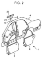
- Figure 2 is an exploded perspective view of components of the first embodiment of Figure 1;
- Figure 3 is an enlarged perspective view of a portion designated as G in Figure 2;
- Figure 4 is an enlarged perspective view of a portion designated as E in Figure 2;
- Figure 5 is a sectional view of the first embodiment taken along line V-V in Figure 1;
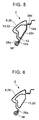
- Figure 6 is a sectional view of the first embodiment taken along line VI-VI in Figure 1;
- Figure 7 is a sectional view of the first embodiment taken along line VII-VII in Figure 1;
- Figure 8 is a sectional view of the first embodiment taken along line VIII-VIII in Figure 1;
- Figure 9 is a sectional view of the first embodiment taken along line IX-IX in Figure 1;
- Figure 10 is a sectional view of the first embodiment taken along line X-X in Figure 1;
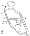
- Figure 11 is a partial perspective view of a body structure of a motor vehicle according to a second embodiment of the present invention;
- Figure 12 is a sectional view of the second embodiment taken along line XII-XII in Figure 11;
- Figure 13 is an enlarged perspective view of a portion designated as J in Figure 12;
- Figure 14 is an enlarged sectional view of a portion designated as J in Figure 12;
- Figure 15 is a sectional view of the second embodiment taken along line XV-XV in Figure 14;
- Figure 16 is a sectional view of the second embodiment taken along line XVI-XVI in Figure 14; and
- Figure 17 is an enlarged sectional view of a portion designated as K in Figure 12.
-
- Hereinafter, the preferred embodiments of the present invention will be explained with reference to the drawings.
- A first embodiment of the present invention will be explained with reference to Figures 1 through 8.
- Referring to Figures 1 and 2, a
reference numeral 1 designates a side body structure of a motor vehicle which is provided with aroof rail section 2, acenter pillar section 4 and aside sill section 6. The vehicleside body structure 1 comprises a side frameouter panel 8, which is an outer panel structure forming an outer section of the vehicle side body structure, and an inner closedsection structure 10. The inner closedsection structure 10 is disposed along the side frameouter panel 8 in a passenger compartment side and forms a part of an inner section of the vehicleside body structure 1. The vehicleside body structure 1 further comprises a plurality ofinner bands 12 which are used to attach the inner closedsection structure 10 to the side frameouter panel 8. - The side frame
outer panel 8 forming the outer panel structure is manufactured by press molding. -
Front doors 7 and rear-doors 9 are respectively attached to the side frame outpanel 8 of the vehicleside body structure 1. - Referring to Figure 2, the inner closed
section structure 10 is composed of aroof rail reinforcement 22, acenter pillar reinforcement 24 and aside sill reinforcement 26. The sectional configurations of the inner closedsection structure 10 change in accordance with changes in the inner side configurations of theroof rail section 2, thecenter pillar section 4 and theside sill section 6 of the side frameouter panel 8. - Referring to Figure 3, an
upper end 24a of thecenter pillar reinforcement 24 is inserted into an opening 22a of theroof rail reinforcement 22 and is connected with aconnection portion 22b of theroof rail reinforcement 22 by welding or the like. Thus, theupper end 24a of thecenter pillar reinforcement 24 is connected with theroof rail reinforcement 22. - Referring to Figure 4, a
lower end 24b of thecenter pillar reinforcement 24 is inserted into an opening 26a of theside sill reinforcement 26 and is connected with aconnection portion 26b of theside sill reinforcement 26 by welding or the like. Thus, thelower end 24b of thecenter pillar reinforcement 24 is connected with theside sill reinforcement 26. - The inner closed
section structure 10 is formed in the following manner. First, theroof rail reinforcement 22, thecenter pillar reinforcement 24 and theside sill reinforcement 26 are respectively manufactured by supplying high-pressure fluid such as oil into raw tubes and then deforming the tubes into predetermined configurations under predetermined conditions of the tube hydraulic forming method. Thereafter, as mentioned above, theupper end 24a of thecenter pillar reinforcement 24 is connected with theroof rail reinforcement 22, and thelower end 24b of thecenter pillar reinforcement 24 is connected with theside sill reinforcement 26. As a result, the integrally formed innerclosed section structure 10 is obtained. - Next, respective sectional configurations of the vehicle
side body structure 1 will be explained with references to Figures 5 through 10. - Referring to Figure 5, in an area of the
roof rail reinforcement 2 of theside body structure 1 in which theinner band 12 is provided, a roof rail outer 28, which is a part of the side frame outer panel 28, is disposed at an outer side. Theroof rail reinforcement 22 of the innerclosed section structure 10 is disposed at the passenger compartment side of the roof rail outer 28, and theinner band 12 is disposed at the passenger compartment side of theroof rail reinforcement 22. Aflange 28a of the roof rail outer 28 and aflange 12a of theinner band 12 are mutually connected. Apart 22c of the surface of theroof rail reinforcement 22 located at an inner side thereof is connected with theinner band 12 by spot welding. Aseal member 36 is attached to theflanges door 9 so that an opening for thedoor 9 is sealed. - Referring to Figure 6, in an area of the
roof rail reinforcement 2 of theside body structure 1 in which theinner band 12 is not provided, the roof rail outer 28, which is a part of the side frameouter panel 8, is disposed at an outer side. Theroof rail reinforcement 22 of the innerclosed section structure 10 is disposed at the passenger compartment side of the roof rail outer 28. The roof rail outer 28 is provided with theflange 28a to which theseal member 36 is attached. Theseal member 36 contacts thedoor 9 so that the opening for thedoor 9 is sealed. - According to the first embodiment of the present invention, the vehicle
side body structure 1 does not need to be provided with an inner section or a roof rail inner of the side body structure, which components need to be provided for the conventional side body structure, since the innerclosed section structure 10 of the first embodiment functions, in the area in which theinner band 12 is not provided, as a part of the inner section or the roof rail inner - Referring to Figure 7, in an area of the
center pillar section 4 of theside body structure 1 in which theinner band 12 is provided, a center pillar outer 30, which is a part of the side frameouter panel 8, is disposed at an outer side. Thecenter pillar reinforcement 24 of the innerclosed section structure 10 is disposed at the passenger compartment side of the center pillar outer 30, and theinner band 12 is disposed at the passenger compartment side of thecenter pillar reinforcement 24. Aflange 30a of the center pillar outer 30 and aflange 12a of theinner band 12 are mutually connected. Apart 24c of the surface of thecenter pillar reinforcement 24 located at an inner side thereof is connected with theinner band 12 by spot welding. Theseal members 36 are attached to theflanges doors doors - Referring to Figure 8, in an area of the
center pillar section 4 of theside body structure 1 in which theinner band 12 is not provided, the center pillar outer 30, which is a part of the side frameouter panel 8, is disposed at an outer side. Thecenter pillar reinforcement 24 of the innerclosed section structure 10 is disposed at the passenger compartment side of the center pillar outer 30. Aflange 30a of the center pillar outer 30 and aflange 12a of theinner band 12 are mutually connected. Apart 24c of the surface of thecenter pillar reinforcement 24 located at an inner side thereof is connected with theinner band 12 by spot welding. Theseal members 36 are attached to theflanges doors doors flanges 30a to which theseal members 36 are respectively attached. Theseal members 36 contact thedoors doors - According to the first embodiment of the present invention, the
side body structure 1 does not need to be provided with an inner section or a center pillar inner of the side body structure, which components need to be provided for the conventional side body structure. This is because the innerclosed section structure 10 functions, in the area in which theinner band 12 is not provided, as a part of the inner section or the center pillar inner. - Referring to Figure 9, in an area of the
side sill section 6 of theside body structure 1 in which theinner band 12 is provided, a side sill outer 32, which is a part of the side frameouter panel 8, is disposed at an outer side. Theside sill reinforcement 26 of the innerclosed section structure 10 is disposed at the passenger compartment side of the side sill outer 32, and theinner band 12 is disposed at the passenger compartment side of theside sill reinforcement 26.Flanges 32a of the side sill outer 32 and theflanges 12a of theinner band 12 are mutually connected. Apart 26c of the surface of theside sill reinforcement 26 located at an inner side thereof is connected with theinner band 12 by spot welding. In theside sill section 6, a plurality of flatplate node members 34 are disposed along theside sill 6 between the side sill outer 32 and theside sill reinforcement 26 so as to increase the rigidity of theside sill section 6 and to prevent the distortion of theside sill section 6. - Referring to Figure 10, in an area of the
side sill section 6 of theside body structure 1 in which theinner band 12 is not provided, the side sill outer 32, which is a part of the side frameouter panel 8, is disposed at an outer side. Theside sill reinforcement 26 of the innerclosed section structure 10 is disposed at the passenger compartment side of the side sill outer 32. - The first embodiment of the present invention has the following advantageous effects.
- The vehicle
side body structure 1 does not need to be provided with the inner section, namely the roof rail inner, the center pillar inner and/or the side sill inner, which components need to be provided for the conventional side body structure. This is because the innerclosed section structure 10 functions, in the area in which theinner band 12 is not provided, as a part of the inner section. - Since the side frame
outer panel 8 forming the outer panel structure is combined with the innerclosed section structure 10 to obtain the vehicleside body structure 1, the rigidity of the vehicleside body structure 1 is increased. - Since the inner
closed section structure 10 is made of a single member, as compared with the conventional side body structure, the amount of material and numbers of components are both decreased and thus the weight of the vehicleside body structure 1 is lightened. - Since the inner
closed section structure 10 is manufactured by the tube hydraulic forming method, the rigidity or stiffness of theside body structure 1 is increased and the weight of theside body structure 1 is decreased, in comparison with the conventional side body structure manufactured by the press molding. - Since the sectional configurations of the inner
closed section structure 10 change in accordance with changes in the inner side configurations of theroof rail section 2, thecenter pillar section 4 and theside sill section 6 of the side frameouter panel 8, the number of the components can be decreased. - Since the
outer panel structure 8 forming the side frameouter panel 8 is disposed at the outer side of the innerclosed section structure 10, the flanges of the side frameouter panel 8 can be effectively utilized as the connection portions with the seal portions and the glasses. - Next, a second embodiment of the present invention will be explained with reference to Figures 11 through 17.
- Referring to Figures 11 and 12, a
body structure 40 of a motor vehicle comprises aroof rail section 2, acenter pillar section 4 and aside sill section 6. In the second embodiment, thevehicle body structure 1 further comprises aroof section 42 and afloor section 44. - The
vehicle body structure 40 is provided with an outer panel structure 50 (only one side thereof is shown in Figure 11) forming an outer section of thebody structure 40. Theouter panel structure 50 is composed of a side frameouter panel 8, a roof railouter panel 52 and a floorouter panel 54. Thesepanels vehicle body structure 40 is further provided with an innerclosed section structure 56 which is composed of aroof reinforcement 58, aroof rail reinforcement 60, acenter pillar reinforcement 62, aside sill reinforcement 64 and afloor cross member 66. Thesereinforcements member 66 are connected to each other by welding or the like to form an integral structure. Thevehicle body structure 40 is further provided with aroof rail inner 68, a center pillar inner 70 and a side sill inner 72 but is not provided with a roof rail inner panel and a floor inner panel. - More specifically, the side frame
outer panel 8, the roof railouter panel 52 and the floorouter panel 54 of theouter panel structure 50 are respectively manufactured by press molding like conventional outer panels. Theouter panels outer panel structure 50 are connected to each other throughflanges - The
roof reinforcement 58, theroof rail reinforcement 60, thecenter pillar reinforcement 62, theside sill reinforcement 64 and thefloor cross member 66 of the innerclosed section structure 56 are respectively manufactured by the above-mentioned tube hydraulic forming method. Namely, at first, high-pressure fluid such as oil is supplied into thereinforcements member 66 under predetermined conditions of the tube hydraulic forming method. Thereafter, thereinforcements member 66 are respectively deformed into predetermined configurations and then connected each other. As a result, the integral innerclosed section structure 56 is obtained. - The sectional configurations of the inner
closed section structure 56 change in accordance with changes in the inner side configurations of theroof rail section 2, thecenter pillar section 4 and theside sill section 6 of theouter panel structure 50. - Referring to Figures 12 and 14, both ends of the
roof reinforcement 58 are respectively connected at connectingportions 74 with upper ends of thecenter pillar reinforcements 62. - Referring to Figures 12 and 17, both ends of the
cross member 66 are respectively connected at connectingportions 76 with lower ends of thecenter pillar reinforcements 62. - Referring to Figures 13 and 15, the
center pillar reinforcement 62 is disposed at an inner side of theroof rail reinforcement 60 so as to intersect vertically theroof rail reinforcement 60. Apart 60a of the inner side surface of theroof rail reinforcement 60 is connected by spot welding with apart 62a of the outer side surface of the intersected portion of thecenter pillar reinforcement 62. Further, apart 62b of the inner side surface of thecenter pillar reinforcement 62 is connected by spot welding with theroof rail inner 68. - Referring to Figures 13 and 17, the
side sill reinforcement 64 is disposed at an inner side of the lower end of thecenter pillar reinforcement 62 so as to intersect vertically thecenter pillar reinforcement 62. Apart 62b of the inner side surface of thecenter pillar reinforcement 62 is connected by spot welding with apart 64a of the outer side surface of the intersected portion of theside sill reinforcement 64. - Referring to Figure 16, the center portion of the
center pillar reinforcement 62 has a sectional configuration including awavy form 62c. - As mentioned above, in the second embodiment, the
vehicle body structure 40 is provided with theroof rail inner 68, the center pillar inner 70 and the side sill inner 72 but is not provided with the roof rail inner panel and the floor inner panel. However, the second embodiment is not limited to the above-mentioned structure. Namely, in the second embodiment, thevehicle body structure 40 may not be provided with any one of the above components, namely, theroof rail inner 68, the center pillar inner 70, the side sill inner 72, the roof rail inner panel and the floor inner panel. Further, in the second embodiment, thevehicle body structure 40 may not be provided with predetermined components taken from thecomponents - The second embodiment of the present invention has the following advantageous effects.
- The inner
closed section structure 56 function as the inner section of thevehicle body structure 40. More specifically, theroof reinforcement 58 and thefloor cross member 66 of the innerclosed section structure 56 respectively function as the roof inner panel in theroof section 42 and the floor inner panel in thefloor section 44 of thevehicle body structure 40. As a result, for example, the roof inner panel and the floor inner panel that are required in the conventional body structure are not required in thevehicle body structure 40 of the second embodiment. - Since the
outer panel structure 50 is combined with the innerclosed section structure 56 to obtain thevehicle body structure 40, the rigidity of thevehicle body structure 40 is increased. Since the innerclosed section structure 56 is an annular structure, the rigidity of thebody structure 50 against a load acting from the side direction of the vehicle is greatly increased. - Since the inner
closed section structure 56 is manufactured by the tube hydraulic forming method, the rigidity of thebody structure 40 is increased and the weight of thebody structure 40 is decreased in comparison with the conventional body structure manufactured by the press molding. - Since the sectional configurations of the inner
closed section structure 56 change in accordance with changes in the inner side configurations of theroof rail section 2, thecenter pillar section 4 and theside sill section 6 of theouter panel structure 50, the number of the components can be decreased. - Since the
outer panel structure 50 such as the side frameouter panel 8 or the like is disposed at the outer side of the innerclosed section structure 56, the flanges of the side frameouter panel 8 or the like forming theouter panel structure 50 can be effectively utilized as the connection portions with the seal portions and the glasses. - Although the present invention has been explained with reference to specific, preferred embodiments, one of ordinary skill in the art will recognize that modifications and improvements can be made while remaining within the scope and spirit of the present invention. The scope of the present invention is determined solely by appended claims.
Claims (10)
- A body structure of a motor vehicle having an inner section and an outer section comprising:an outer panel structure forming the outer section of the body structure; andan inner closed section structure disposed along an inner side configuration of the outer panel structure and attached to the outer panel structure, said inner closed section structure having a sectional configuration which changes in accordance with changes in the inner side configuration of the outer panel structure and having a closed section which is made of a single member, said outer panel structure having a part which functions as the inner section of the body structure.
- A body structure of a motor vehicle according to claim 1, wherein said outer panel structure is an integral panel forming at least a roof rail outer and a center pillar outer, and said inner closed section structure is integrally disposed along areas of the roof rail outer and the center pillar outer of the outer panel structure.
- A body structure of a motor vehicle according to claim 1, wherein said outer panel structure is an integral panel forming at least a center pillar outer and a side sill outer, and said inner closed section structure is integrally disposed along areas of the center pillar outer and the side sill outer of the outer panel structure.
- A body structure of a motor vehicle according to claim 1, wherein said outer panel structure is an integral panel forming at least a center pillar outer and a roof outer, and said inner closed section structure is integrally disposed along areas of the center pillar outer and the roof outer of the outer panel structure.
- A body structure of a motor vehicle according to claim 1, wherein said outer panel structure is an integral panel forming at least a center pillar outer and a floor outer, and said inner closed section structure is integrally disposed along areas of the center pillar outer and the floor outer of the outer panel structure.
- A body structure of a motor vehicle according to any of claims 1-5, wherein said inner closed section structure has a closed section integrally disposed along areas of a center pillar section, a roof section and a floor section of the outer panel structure.
- A body structure of a motor vehicle according to any of claims 1-6, wherein said inner closed section structure has a closed section integrally disposed along areas of a center pillar section, a roof section, a floor section and a roof rail section of the outer panel structure.
- A body structure of a motor vehicle according to any of claims 1-7, wherein said inner closed section structure has a closed section integrally disposed along areas of a center pillar section, a roof section, a floor section and a side sill of the outer panel structure.
- A body structure of a motor vehicle according to any of claims 1-8, wherein said outer panel structure is manufactured by press molding, and said inner closed section structure is manufactured by a tube hydraulic forming method.
- A body structure of a motor vehicle according to claim 2, wherein said integral panel of the outer panel structure has a flange to which seal means is attached.
Applications Claiming Priority (2)
| Application Number | Priority Date | Filing Date | Title |
|---|---|---|---|
| JP02310599A JP3500626B2 (en) | 1999-01-29 | 1999-01-29 | Vehicle body structure |
| JP2310599 | 1999-01-29 |
Publications (2)
| Publication Number | Publication Date |
|---|---|
| EP1024073A1 true EP1024073A1 (en) | 2000-08-02 |
| EP1024073B1 EP1024073B1 (en) | 2003-05-14 |
Family
ID=12101196
Family Applications (1)
| Application Number | Title | Priority Date | Filing Date |
|---|---|---|---|
| EP00101711A Expired - Lifetime EP1024073B1 (en) | 1999-01-29 | 2000-01-27 | Body structure of motor vehicle |
Country Status (5)
| Country | Link |
|---|---|
| US (1) | US6322135B1 (en) |
| EP (1) | EP1024073B1 (en) |
| JP (1) | JP3500626B2 (en) |
| KR (1) | KR20000053613A (en) |
| DE (1) | DE60002616T2 (en) |
Cited By (9)
| Publication number | Priority date | Publication date | Assignee | Title |
|---|---|---|---|---|
| WO2003035453A1 (en) * | 2001-10-19 | 2003-05-01 | Daimlerchrysler Ag | Lateral wall module for the body of a motor vehicle |
| FR2847875A1 (en) * | 2002-12-03 | 2004-06-04 | Renault Sa | BODY ASSEMBLY FOR A MOTOR VEHICLE AND VEHICLE COMPRISING AT LEAST ONE SUCH ASSEMBLY |
| EP1382513A3 (en) * | 2002-07-17 | 2004-09-08 | Bayerische Motoren Werke Aktiengesellschaft | Vehicle body with a B-pillar |
| FR2901229A1 (en) * | 2006-05-18 | 2007-11-23 | Renault Sas | CONNECTION BETWEEN THE PAVILION TRAVERSE AND THE UPPER FOOT REINFORCEMENT OF A MOTOR VEHICLE |
| ITBO20090492A1 (en) * | 2009-07-28 | 2011-01-29 | Ferrari Spa | FRAME OF A VEHICLE EQUIPPED WITH AN EXTRUDED CENTRAL UPRIGHT |
| DE102006051991B4 (en) * | 2005-11-04 | 2011-06-16 | Honda Motor Co., Ltd. | Vehicle body structure which is reinforced against a side impact |
| EP2336007A1 (en) * | 2009-12-18 | 2011-06-22 | Audi AG | Side sill assembly for a vehicle body and method for producing the same |
| CN107364493A (en) * | 2016-04-25 | 2017-11-21 | 铃木株式会社 | The roof rail of vehicle |
| CN112092914A (en) * | 2019-06-18 | 2020-12-18 | 马自达汽车株式会社 | Upper vehicle body structure of vehicle |
Families Citing this family (48)
| Publication number | Priority date | Publication date | Assignee | Title |
|---|---|---|---|---|
| US6623067B2 (en) * | 1997-10-16 | 2003-09-23 | Magna International Inc. | Door seal interface structure for a motor vehicle space frame |
| JP3428545B2 (en) * | 2000-01-07 | 2003-07-22 | 本田技研工業株式会社 | Body reinforcement structure |
| DE20005471U1 (en) * | 2000-03-23 | 2000-06-21 | Benteler Ag, 33104 Paderborn | Instrument holder |
| JP4586267B2 (en) * | 2000-12-20 | 2010-11-24 | マツダ株式会社 | Upper body structure of the vehicle |
| US6409256B1 (en) * | 2001-01-23 | 2002-06-25 | Guardian Industries Corp. | Multi-piece applique for vehicle B-pillar |
| DE10117009B4 (en) * | 2001-04-05 | 2005-04-21 | Daimlerchrysler Ag | Support column for a body frame of a motor vehicle |
| JP3830401B2 (en) | 2001-06-04 | 2006-10-04 | 株式会社丸順 | Structure around the vehicle door opening |
| US6619729B2 (en) * | 2001-06-07 | 2003-09-16 | Mazda Motor Corporation | Side body structure of vehicle |
| JP3969054B2 (en) * | 2001-10-25 | 2007-08-29 | 三菱自動車エンジニアリング株式会社 | Vehicle pillar substructure |
| US6957845B2 (en) * | 2003-07-31 | 2005-10-25 | Dana Corporation | Space frame cross member with integrated door seal feature |
| JP4151527B2 (en) * | 2003-09-03 | 2008-09-17 | 日産自動車株式会社 | Body side structure |
| US7253374B2 (en) * | 2003-09-15 | 2007-08-07 | General Motors Corporation | Sheet-to-tube welded structure and method |
| US20060001294A1 (en) * | 2004-07-01 | 2006-01-05 | Balgaard Steven P | Rocker assembly for vehicles |
| JP4465599B2 (en) * | 2004-09-10 | 2010-05-19 | スズキ株式会社 | Joint structure at the top of the center pillar |
| DE102004053917B3 (en) * | 2004-11-05 | 2006-04-13 | Benteler Automobiltechnik Gmbh | Sidewall of a motor vehicle |
| US7213874B2 (en) * | 2005-03-09 | 2007-05-08 | Nissan Technical Center North America, Inc. | Vehicle roof structure |
| US7357448B2 (en) * | 2005-06-06 | 2008-04-15 | Ford Global Technologies, Llc | Unitary hydroformed roof support pillar |
| DE102005040718B4 (en) * | 2005-08-27 | 2012-11-22 | Volkswagen Ag | support structure |
| US7293823B2 (en) * | 2005-11-16 | 2007-11-13 | Ford Global Technologies, Llc | Interlocked pillar and roof rail joint |
| JP2007191008A (en) * | 2006-01-18 | 2007-08-02 | Kobe Steel Ltd | Automobile side sill |
| US7677652B2 (en) * | 2006-03-29 | 2010-03-16 | Nissan Technical Center North America, Inc. | Roof inner body structure |
| EP2527233B1 (en) * | 2007-04-04 | 2014-05-14 | Nippon Steel & Sumitomo Metal Corporation | Strength member for an automobile body |
| JP4445522B2 (en) * | 2007-06-20 | 2010-04-07 | 豊田鉄工株式会社 | Reinforcing member for vehicle center pillar |
| JP4852017B2 (en) * | 2007-08-06 | 2012-01-11 | 本田技研工業株式会社 | Body superstructure |
| JP5003424B2 (en) * | 2007-11-19 | 2012-08-15 | トヨタ車体株式会社 | Automobile roof structure |
| DE102008022641B4 (en) * | 2008-05-08 | 2012-03-22 | Daimler Ag | Car body with a pillar and a roof frame element |
| DE102008024762A1 (en) * | 2008-05-23 | 2009-12-10 | Daimler Ag | Connection arrangement for center pillar of car, particularly four doors motor vehicle cabriolet or two-seater of motor vehicle, has longitudinal chassis beam with outer and inner sheet metal shells closing longitudinal chassis beam |
| JP5262305B2 (en) * | 2008-05-30 | 2013-08-14 | 新日鐵住金株式会社 | Reinforcing members, pillars and car bodies |
| JP5272623B2 (en) * | 2008-09-30 | 2013-08-28 | マツダ株式会社 | Manufacturing method of automobile body |
| JP5347410B2 (en) * | 2008-09-30 | 2013-11-20 | マツダ株式会社 | Manufacturing method of automobile body |
| US8662567B2 (en) * | 2009-02-02 | 2014-03-04 | Vari-Form, Inc. | Vehicle roof support pillar assembly |
| JP5063757B2 (en) * | 2010-08-17 | 2012-10-31 | 本田技研工業株式会社 | Body side structure |
| US8702161B2 (en) * | 2010-12-22 | 2014-04-22 | Tesla Motors, Inc. | System for absorbing and distributing side impact energy utilizing an integrated battery pack and side sill assembly |
| US20120161472A1 (en) | 2010-12-22 | 2012-06-28 | Tesla Motors, Inc. | System for Absorbing and Distributing Side Impact Energy Utilizing an Integrated Battery Pack |
| DE102012004761A1 (en) * | 2012-03-08 | 2013-09-12 | GM Global Technology Operations LLC (n. d. Gesetzen des Staates Delaware) | Reinforcing part for a roof side rail |
| DE102013002306A1 (en) * | 2013-02-06 | 2014-08-07 | GM Global Technology Operations LLC (n. d. Ges. d. Staates Delaware) | B-pillar of motor vehicle, has base structure that extends in direction of roof region and under frame of vehicle during installed state of pillar, and formed with interconnected pipes extended in longitudinal direction |
| JP6105386B2 (en) * | 2013-05-21 | 2017-03-29 | 豊田鉄工株式会社 | Vehicle side structure |
| US9139235B2 (en) | 2013-05-21 | 2015-09-22 | Ford Global Technologies, Llc | Vehicle frame rail and pillar connection |
| KR101491319B1 (en) * | 2013-09-30 | 2015-02-06 | 현대자동차주식회사 | Outer panel for pillar of vehicle, method and rolling apparatus for manufacturing the same |
| US9073586B1 (en) * | 2014-06-27 | 2015-07-07 | Ford Global Technologies, Llc | Transverse sill reinforcement for a truck bed and method of making a sill reinforcement |
| JP2016074382A (en) * | 2014-10-09 | 2016-05-12 | トヨタ自動車株式会社 | Vehicle upper structure |
| US9821852B2 (en) * | 2016-02-03 | 2017-11-21 | Ford Global Technologies Llc | Pressurized air insert for side impacts |
| DE102016001241A1 (en) * | 2016-02-04 | 2017-08-10 | GM Global Technology Operations LLC (n. d. Ges. d. Staates Delaware) | Structure node for a motor vehicle body |
| JP6489088B2 (en) * | 2016-08-26 | 2019-03-27 | トヨタ自動車株式会社 | Vehicle frame structure |
| JP7287263B2 (en) * | 2019-12-19 | 2023-06-06 | マツダ株式会社 | Vehicle side body structure |
| MX2022008267A (en) | 2020-01-03 | 2022-08-04 | Tesla Inc | Selective extraction of lithium from clay minerals. |
| KR20230067148A (en) | 2021-11-09 | 2023-05-16 | 현대자동차주식회사 | Body for vehicle |
| KR20230107940A (en) * | 2022-01-10 | 2023-07-18 | 현대자동차주식회사 | Body structure |
Citations (8)
| Publication number | Priority date | Publication date | Assignee | Title |
|---|---|---|---|---|
| US4355843A (en) * | 1979-10-16 | 1982-10-26 | Toyo Kogyo Co., Ltd. | Pillar construction for motor vehicle |
| US4944553A (en) * | 1989-06-30 | 1990-07-31 | Chrysler Corporation | Vehicle reinforcing structure |
| DE19518946A1 (en) * | 1994-05-24 | 1995-11-30 | Honda Motor Co Ltd | Structural element of vehicle constructed of alloy plates |
| DE19531874C1 (en) * | 1995-08-30 | 1996-10-02 | Daimler Benz Ag | Side wall sub assembly |
| DE19708905A1 (en) * | 1997-03-05 | 1998-04-16 | Daimler Benz Ag | Profiled frame element for A-pillar used in car body |
| EP0856455A2 (en) * | 1997-01-31 | 1998-08-05 | Mazda Motor Corporation | Body structure for vehicle |
| DE19805804A1 (en) * | 1997-02-12 | 1998-08-13 | Saab Automobile | Construction of bodywork for vehicle |
| JPH10218017A (en) * | 1997-01-31 | 1998-08-18 | Nissan Motor Co Ltd | Center pillar reinforcement structure |
Family Cites Families (13)
| Publication number | Priority date | Publication date | Assignee | Title |
|---|---|---|---|---|
| JP2550700Y2 (en) * | 1991-07-19 | 1997-10-15 | マツダ株式会社 | Car side body structure |
| DE3918280A1 (en) | 1989-06-05 | 1990-12-06 | Audi Ag | MOTOR VEHICLE BODY |
| US5352011A (en) * | 1991-11-11 | 1994-10-04 | Mazda Motor Corporation | Body structure of an automotive vehicle |
| US5388885A (en) * | 1993-02-01 | 1995-02-14 | General Motors Corporation | Body structure of a motor vehicle |
| JP3335781B2 (en) * | 1994-08-31 | 2002-10-21 | 富士重工業株式会社 | Closed cross-sectional structure around the center pillar of a vehicle |
| JP3335780B2 (en) * | 1994-08-31 | 2002-10-21 | 富士重工業株式会社 | Body structure below the center pillar of the vehicle |
| JPH08192238A (en) | 1995-01-12 | 1996-07-30 | Tube Forming:Kk | Frame forming method |
| DE19519353A1 (en) | 1995-05-26 | 1996-11-28 | Porsche Ag | Carrier of a vehicle body structure and method for its production |
| JPH0930345A (en) | 1995-07-18 | 1997-02-04 | Nissan Motor Co Ltd | Body structure tubular member and method of manufacturing the same |
| JPH09150752A (en) | 1995-09-29 | 1997-06-10 | Honda Motor Co Ltd | Body frame manufacturing method |
| JP3302272B2 (en) | 1996-11-06 | 2002-07-15 | 本田技研工業株式会社 | Body frame manufacturing method |
| JP3473729B2 (en) | 1996-11-06 | 2003-12-08 | 本田技研工業株式会社 | Body frame manufacturing method |
| JPH10138950A (en) | 1996-11-12 | 1998-05-26 | Nissan Motor Co Ltd | Impact absorbing member and method of manufacturing the same |
-
1999
- 1999-01-29 JP JP02310599A patent/JP3500626B2/en not_active Expired - Fee Related
-
2000
- 2000-01-26 KR KR1020000003571A patent/KR20000053613A/en not_active Withdrawn
- 2000-01-27 EP EP00101711A patent/EP1024073B1/en not_active Expired - Lifetime
- 2000-01-27 DE DE60002616T patent/DE60002616T2/en not_active Expired - Lifetime
- 2000-01-28 US US09/493,177 patent/US6322135B1/en not_active Expired - Lifetime
Patent Citations (8)
| Publication number | Priority date | Publication date | Assignee | Title |
|---|---|---|---|---|
| US4355843A (en) * | 1979-10-16 | 1982-10-26 | Toyo Kogyo Co., Ltd. | Pillar construction for motor vehicle |
| US4944553A (en) * | 1989-06-30 | 1990-07-31 | Chrysler Corporation | Vehicle reinforcing structure |
| DE19518946A1 (en) * | 1994-05-24 | 1995-11-30 | Honda Motor Co Ltd | Structural element of vehicle constructed of alloy plates |
| DE19531874C1 (en) * | 1995-08-30 | 1996-10-02 | Daimler Benz Ag | Side wall sub assembly |
| EP0856455A2 (en) * | 1997-01-31 | 1998-08-05 | Mazda Motor Corporation | Body structure for vehicle |
| JPH10218017A (en) * | 1997-01-31 | 1998-08-18 | Nissan Motor Co Ltd | Center pillar reinforcement structure |
| DE19805804A1 (en) * | 1997-02-12 | 1998-08-13 | Saab Automobile | Construction of bodywork for vehicle |
| DE19708905A1 (en) * | 1997-03-05 | 1998-04-16 | Daimler Benz Ag | Profiled frame element for A-pillar used in car body |
Non-Patent Citations (1)
| Title |
|---|
| PATENT ABSTRACTS OF JAPAN vol. 1998, no. 13 30 November 1998 (1998-11-30) * |
Cited By (19)
| Publication number | Priority date | Publication date | Assignee | Title |
|---|---|---|---|---|
| WO2003035453A1 (en) * | 2001-10-19 | 2003-05-01 | Daimlerchrysler Ag | Lateral wall module for the body of a motor vehicle |
| US7032959B2 (en) | 2001-10-19 | 2006-04-25 | Daimlerchrysler Ag | Lateral wall module for the body of a motor vehicle |
| EP1382513A3 (en) * | 2002-07-17 | 2004-09-08 | Bayerische Motoren Werke Aktiengesellschaft | Vehicle body with a B-pillar |
| FR2847875A1 (en) * | 2002-12-03 | 2004-06-04 | Renault Sa | BODY ASSEMBLY FOR A MOTOR VEHICLE AND VEHICLE COMPRISING AT LEAST ONE SUCH ASSEMBLY |
| WO2004052707A3 (en) * | 2002-12-03 | 2004-08-12 | Renault Sa | Motor vehicle body assembly and motor vehicle comprising at least such an assembly |
| DE102006051991B4 (en) * | 2005-11-04 | 2011-06-16 | Honda Motor Co., Ltd. | Vehicle body structure which is reinforced against a side impact |
| RU2412850C2 (en) * | 2006-05-18 | 2011-02-27 | Рено С.А.С | Coupling between roof transverse beam and top reinforcing element of car central pillar |
| WO2007135302A1 (en) * | 2006-05-18 | 2007-11-29 | Renault S.A.S | Connection between the roof cross-member and the upper center pillar reinforcement of a motor vehicle |
| CN101448696B (en) * | 2006-05-18 | 2011-04-06 | 雷诺股份公司 | Connection between roof cross members and upper center pillar reinforcements of motor vehicles |
| FR2901229A1 (en) * | 2006-05-18 | 2007-11-23 | Renault Sas | CONNECTION BETWEEN THE PAVILION TRAVERSE AND THE UPPER FOOT REINFORCEMENT OF A MOTOR VEHICLE |
| US7963591B2 (en) | 2006-05-18 | 2011-06-21 | Renault S.A.S. | Connection between the roof cross-member and the upper center pillar reinforcement of a motor vehicle |
| ITBO20090492A1 (en) * | 2009-07-28 | 2011-01-29 | Ferrari Spa | FRAME OF A VEHICLE EQUIPPED WITH AN EXTRUDED CENTRAL UPRIGHT |
| EP2279928A3 (en) * | 2009-07-28 | 2011-09-07 | Ferrari S.p.A. | Chassis of a vehicle provided with an extruded central pillar |
| US8272682B2 (en) | 2009-07-28 | 2012-09-25 | Studio Torta S.p.A. | Chassis of a vehicle provided with an extruded central pillar |
| EP2336007A1 (en) * | 2009-12-18 | 2011-06-22 | Audi AG | Side sill assembly for a vehicle body and method for producing the same |
| CN107364493A (en) * | 2016-04-25 | 2017-11-21 | 铃木株式会社 | The roof rail of vehicle |
| CN107364493B (en) * | 2016-04-25 | 2019-08-13 | 铃木株式会社 | The roof rail of vehicle |
| CN112092914A (en) * | 2019-06-18 | 2020-12-18 | 马自达汽车株式会社 | Upper vehicle body structure of vehicle |
| EP3753811A1 (en) * | 2019-06-18 | 2020-12-23 | Mazda Motor Corporation | Vehicle-body structure for vehicle, and vehicle |
Also Published As
| Publication number | Publication date |
|---|---|
| EP1024073B1 (en) | 2003-05-14 |
| DE60002616T2 (en) | 2004-02-26 |
| US6322135B1 (en) | 2001-11-27 |
| KR20000053613A (en) | 2000-08-25 |
| JP2000219154A (en) | 2000-08-08 |
| JP3500626B2 (en) | 2004-02-23 |
| DE60002616D1 (en) | 2003-06-18 |
Similar Documents
| Publication | Publication Date | Title |
|---|---|---|
| EP1024073A1 (en) | Body structure of motor vehicle | |
| US6217109B1 (en) | Body structure of motor vehicle | |
| US6102472A (en) | Vehicle body comprising a lower body part and an upper body part, as well as a method of manufacturing an upper body part for such vehicle body | |
| US8651562B2 (en) | B-pillar reinforcement of a motor vehicle | |
| US6692065B2 (en) | Framing structure around vehicle door opening | |
| US6416114B1 (en) | Side impact beam | |
| EP1007399B1 (en) | Integral body and frame for an automobile | |
| US6428085B1 (en) | Body structure in floor section of vehicle | |
| CZ48294A3 (en) | Shaped beam, and process for producing thereof | |
| KR980009009A (en) | Floor assemblies for vehicles, especially passenger cars | |
| US6073993A (en) | Body structure for a motor vehicle | |
| US7585017B2 (en) | One-piece, tubular member with an integrated welded flange and associated method for producing | |
| CN111824266B (en) | Side sill assembly for a motor vehicle | |
| US6305738B1 (en) | Door frame for a motor vehicle | |
| EP1199245B1 (en) | Profile for body section | |
| CN101208236A (en) | One-piece tubular component with integral welded flange and related manufacturing method | |
| GB2280456A (en) | Reinforcing beam | |
| JP2979763B2 (en) | Vehicle frame structure | |
| JP3590965B2 (en) | Vehicle body structure | |
| US7703207B2 (en) | Blank, chassis component and method for production of said chassis component | |
| KR100524638B1 (en) | Vehicle Body Frame Structure | |
| KR102699817B1 (en) | Separated Al cross member | |
| KR100456559B1 (en) | Aluminum seat frame for an automobile | |
| JPH05270263A (en) | Door beam | |
| CN117208090A (en) | A lightweight side structure for non-load-bearing off-road vehicles |
Legal Events
| Date | Code | Title | Description |
|---|---|---|---|
| PUAI | Public reference made under article 153(3) epc to a published international application that has entered the european phase |
Free format text: ORIGINAL CODE: 0009012 |
|
| AK | Designated contracting states |
Kind code of ref document: A1 Designated state(s): DE ES FR GB IT |
|
| AX | Request for extension of the european patent |
Free format text: AL;LT;LV;MK;RO;SI |
|
| 17P | Request for examination filed |
Effective date: 20001116 |
|
| AKX | Designation fees paid |
Free format text: DE ES FR GB IT |
|
| GRAH | Despatch of communication of intention to grant a patent |
Free format text: ORIGINAL CODE: EPIDOS IGRA |
|
| GRAH | Despatch of communication of intention to grant a patent |
Free format text: ORIGINAL CODE: EPIDOS IGRA |
|
| GRAA | (expected) grant |
Free format text: ORIGINAL CODE: 0009210 |
|
| AK | Designated contracting states |
Designated state(s): DE ES FR GB IT |
|
| PG25 | Lapsed in a contracting state [announced via postgrant information from national office to epo] |
Ref country code: IT Free format text: LAPSE BECAUSE OF FAILURE TO SUBMIT A TRANSLATION OF THE DESCRIPTION OR TO PAY THE FEE WITHIN THE PRESCRIBED TIME-LIMIT;WARNING: LAPSES OF ITALIAN PATENTS WITH EFFECTIVE DATE BEFORE 2007 MAY HAVE OCCURRED AT ANY TIME BEFORE 2007. THE CORRECT EFFECTIVE DATE MAY BE DIFFERENT FROM THE ONE RECORDED. Effective date: 20030514 |
|
| REG | Reference to a national code |
Ref country code: GB Ref legal event code: FG4D |
|
| REF | Corresponds to: |
Ref document number: 60002616 Country of ref document: DE Date of ref document: 20030618 Kind code of ref document: P |
|
| PG25 | Lapsed in a contracting state [announced via postgrant information from national office to epo] |
Ref country code: ES Free format text: LAPSE BECAUSE OF FAILURE TO SUBMIT A TRANSLATION OF THE DESCRIPTION OR TO PAY THE FEE WITHIN THE PRESCRIBED TIME-LIMIT Effective date: 20030825 |
|
| PGFP | Annual fee paid to national office [announced via postgrant information from national office to epo] |
Ref country code: FR Payment date: 20040108 Year of fee payment: 5 |
|
| PGFP | Annual fee paid to national office [announced via postgrant information from national office to epo] |
Ref country code: GB Payment date: 20040121 Year of fee payment: 5 |
|
| ET | Fr: translation filed | ||
| PLBE | No opposition filed within time limit |
Free format text: ORIGINAL CODE: 0009261 |
|
| STAA | Information on the status of an ep patent application or granted ep patent |
Free format text: STATUS: NO OPPOSITION FILED WITHIN TIME LIMIT |
|
| 26N | No opposition filed |
Effective date: 20040217 |
|
| PG25 | Lapsed in a contracting state [announced via postgrant information from national office to epo] |
Ref country code: GB Free format text: LAPSE BECAUSE OF NON-PAYMENT OF DUE FEES Effective date: 20050127 |
|
| GBPC | Gb: european patent ceased through non-payment of renewal fee |
Effective date: 20050127 |
|
| PG25 | Lapsed in a contracting state [announced via postgrant information from national office to epo] |
Ref country code: FR Free format text: LAPSE BECAUSE OF NON-PAYMENT OF DUE FEES Effective date: 20050930 |
|
| REG | Reference to a national code |
Ref country code: FR Ref legal event code: ST |
|
| PGFP | Annual fee paid to national office [announced via postgrant information from national office to epo] |
Ref country code: DE Payment date: 20170125 Year of fee payment: 18 |
|
| REG | Reference to a national code |
Ref country code: DE Ref legal event code: R119 Ref document number: 60002616 Country of ref document: DE |
|
| PG25 | Lapsed in a contracting state [announced via postgrant information from national office to epo] |
Ref country code: DE Free format text: LAPSE BECAUSE OF NON-PAYMENT OF DUE FEES Effective date: 20180801 |