EP1028075B1 - Automatische Maschine zum wenden von Behältern - Google Patents
Automatische Maschine zum wenden von Behältern Download PDFInfo
- Publication number
- EP1028075B1 EP1028075B1 EP00200287A EP00200287A EP1028075B1 EP 1028075 B1 EP1028075 B1 EP 1028075B1 EP 00200287 A EP00200287 A EP 00200287A EP 00200287 A EP00200287 A EP 00200287A EP 1028075 B1 EP1028075 B1 EP 1028075B1
- Authority
- EP
- European Patent Office
- Prior art keywords
- machine according
- containers
- gripping
- consist
- rotating
- Prior art date
- Legal status (The legal status is an assumption and is not a legal conclusion. Google has not performed a legal analysis and makes no representation as to the accuracy of the status listed.)
- Expired - Lifetime
Links
- 238000006073 displacement reaction Methods 0.000 claims description 2
- 230000004913 activation Effects 0.000 claims 1
- 238000000151 deposition Methods 0.000 description 2
- 238000004806 packaging method and process Methods 0.000 description 2
- 230000001360 synchronised effect Effects 0.000 description 2
- 230000001174 ascending effect Effects 0.000 description 1
- 230000008021 deposition Effects 0.000 description 1
- 238000007599 discharging Methods 0.000 description 1
- 238000004064 recycling Methods 0.000 description 1
- 230000000284 resting effect Effects 0.000 description 1
- 230000000630 rising effect Effects 0.000 description 1
- 238000005096 rolling process Methods 0.000 description 1
- 238000007789 sealing Methods 0.000 description 1
Images


Classifications
-
- B—PERFORMING OPERATIONS; TRANSPORTING
- B65—CONVEYING; PACKING; STORING; HANDLING THIN OR FILAMENTARY MATERIAL
- B65G—TRANSPORT OR STORAGE DEVICES, e.g. CONVEYORS FOR LOADING OR TIPPING, SHOP CONVEYOR SYSTEMS OR PNEUMATIC TUBE CONVEYORS
- B65G47/00—Article or material-handling devices associated with conveyors; Methods employing such devices
- B65G47/22—Devices influencing the relative position or the attitude of articles during transit by conveyors
- B65G47/24—Devices influencing the relative position or the attitude of articles during transit by conveyors orientating the articles
- B65G47/248—Devices influencing the relative position or the attitude of articles during transit by conveyors orientating the articles by turning over or inverting them
- B65G47/252—Devices influencing the relative position or the attitude of articles during transit by conveyors orientating the articles by turning over or inverting them about an axis substantially perpendicular to the conveying direction
-
- B—PERFORMING OPERATIONS; TRANSPORTING
- B65—CONVEYING; PACKING; STORING; HANDLING THIN OR FILAMENTARY MATERIAL
- B65G—TRANSPORT OR STORAGE DEVICES, e.g. CONVEYORS FOR LOADING OR TIPPING, SHOP CONVEYOR SYSTEMS OR PNEUMATIC TUBE CONVEYORS
- B65G29/00—Rotary conveyors, e.g. rotating discs, arms, star-wheels or cones
-
- B—PERFORMING OPERATIONS; TRANSPORTING
- B65—CONVEYING; PACKING; STORING; HANDLING THIN OR FILAMENTARY MATERIAL
- B65G—TRANSPORT OR STORAGE DEVICES, e.g. CONVEYORS FOR LOADING OR TIPPING, SHOP CONVEYOR SYSTEMS OR PNEUMATIC TUBE CONVEYORS
- B65G47/00—Article or material-handling devices associated with conveyors; Methods employing such devices
- B65G47/74—Feeding, transfer, or discharging devices of particular kinds or types
- B65G47/84—Star-shaped wheels or devices having endless travelling belts or chains, the wheels or devices being equipped with article-engaging elements
- B65G47/846—Star-shaped wheels or wheels equipped with article-engaging elements
- B65G47/847—Star-shaped wheels or wheels equipped with article-engaging elements the article-engaging elements being grippers
Definitions
- the present invention relates to a machine for overturning containers such as bottles having a bottom which is not flat and the like.
- the containers are therefore inserted into specials supports which are substantially parallelepiped and which have an internal seat corresponding to the shape of the container and the associated bottom so that the support/container assembly may be fed towards the filling machine, inside which the container, still carried by the associated support, is filled and sealed with a stopper and unloaded from the machine for the subsequent packaging operations, before performing which operations the container must be separated from its support which is in turn recycled and brought back to the loading station or to an associated store.
- the technical problem which is posed, therefore, is that of providing an automatic apparatus for application to conventional lines for filling and packaging containers such as bottles and the like, in particular those without a flat bottom, which is designed to remove a container from an associated support, overturn it through 180° and feed it to the conveyors belts (or similar conveying devices) on which it rests at its end with the stopper which has a flat upper surface suitable for acting as a base for the overturned container, thus allowing conveying thereof without the need for an auxiliary support.
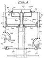
- an embodiment of the machine according to the present invention is composed essentially of a fixed base 100 on which a fixed upright 200 is mounted, the latter having, coaxially inserted inside it, a rotating column 250 on which the following are coaxially mounted:
- a conveyor belt 500 for feeding the bottles 10 which are contained in associated supports 20 and supplied from a filling machine (not shown), means 550 for inserting the supports into the machine, a conveyor belt 600 for conveying away the overturned bottles 10, means 650 for pushing the bottles onto said belt 600, a conveyor belt 700 for recycling the supports to the filling machine, not shown.
- the devices 300 for gripping and handling the bottles 10 consist of guides 310 which are integrally joined to the plate 260 rotating together with the column 250 and which have, sliding inside them, a sliding member 311 which has at its free end a shaped arm 312 on which the means 320 for gripping and overturning the bottle 10 are mounted.
- Said gripping means 320 consist of a gripper 321, the jaws 321a of which are opened (Fig. 5a) and closed (Fig. 5b) by means of a cylinder 322, the piston 322a of which is normally kept pushed outwards by a spring 323 so as to ensure a stable condition of the open jaws 321a.
- the piston By suitably supplying the cylinder by means of the associated valves 322b, the piston is pushed inwards, overcoming the resistance of the spring 323 and causing closing of the jaws 321a around the bottle 10; when the cylinder is discharged, the spring 323 moves the piston outwards again and causes the jaws to open.
- the entire jaw group 320 is in turn mounted by means of a pivot 331 on a rotating piston 332 which is integral with the arm 312.
- the fixed annular cam 400 is also mounted coaxially with the column 250, said cam having, rolling along its shaped profile, rollers 313, the hub 313a of which is inserted inside a longitudinal eyelet 310a of the guide 310 and integrally joined to each sliding member 311 sliding inside the said guide 310.
- the cam 400 causes, during rotation of the plate 260, the correct and synchronised sequence of raising/lowering of the sliding members 311 of the means 300 for handling the containers 10.
- a ring 820 is mounted coaxially on the top end of the column 260, said ring having formed along its annular edge 820a two cam profiles 821 and 822 along which rollers 801a,802a associated with sensors 801,802 travel, the latter being attached to a disc 760 which is coaxially mounted on the column 250 and attached to each guide 310 of the devices 300 for handling the bottle 10, together with which it rotates.
- Said sensors 801,802 are connected to the devices (known per se and therefore not shown) for controlling and actuating the working sequence of the machine and respectively designed to send enable signals for closing/opening and rotating the gripper 320 for gripping the bottle 10.
- the machine according to the invention may also be used for overturning containers with a flat bottom to be selected, for example, for unloading in different directions: in this case it is possible, for example, for some containers (overturned or not overturned) to continue, being carried by the plate 280, towards the belt 700, while other containers removed by the gripping means 320 (overturned/not overturned) are transported towards the belt 600, selection being determined by the correct use of the control and actuating means and the correct timing of the cycle times.
Landscapes
- Engineering & Computer Science (AREA)
- Mechanical Engineering (AREA)
- Specific Conveyance Elements (AREA)
- Attitude Control For Articles On Conveyors (AREA)
- Supplying Of Containers To The Packaging Station (AREA)
- Vending Machines For Individual Products (AREA)
- Control And Other Processes For Unpacking Of Materials (AREA)
- Filling Of Jars Or Cans And Processes For Cleaning And Sealing Jars (AREA)
Claims (18)
- Vorrichtung zum Umdrehen von Behältern (10) mit einer feststehenden Basis (100, 200), die sich entlang einer Kreisbahn bewegende Bewegungsmittel (250, 280) für die Behälter (10) hält, wobei Einrichtungen zum Greifen/Loslassen (321), Einrichtungen zum Anheben/Absenken (300) in eine im Wesentlichen im rechten Winkel zur Bewegungsrichtung ausgerichtete Richtung und Mittel zum Umdrehen (330) der Behälter (10) mit den Bewegungsmitteln (250) ein Ganzes bildend verbunden sind, wobei den Mitteln (250) und Einrichtungen (300, 320, 330) Mittel (400, 821, 822) zum Steuern und Ausführen der entsprechenden Arbeitsfolgen zugeordnet sind, wobei die Mittel zum Steuern des Öffnens/Schließens und des Drehens der Greifmittel (320) ein Paar von jedem Greifgerät zugeordneten Sensoren (801, 802) aufweisen,
dadurch gekennzeichnet, dass
die Sensoren (801, 802) fest an einer koaxial an der Säule (260) angebrachten und mit dieser sich drehenden Scheibe (760) angebracht sind und dass die Sensoren (801, 802) über eine Betätigungseinrichtung verfügen, die jeweils auf das Profil einer feststehenden, ringförmigen Steuerscheibe (821, 822) einwirkt, die koaxial und ruhigstehend an der Säule (260) angebracht ist. - Vorrichtung nach Anspruch 1, dadurch gekennzeichnet, dass diese vom sich drehenden Typ ist.
- Vorrichtung nach Anspruch 1, dadurch gekennzeichnet, dass das Bewegungsmittel eine sich drehende Säule (250) aufweist, an der koaxial eine sich mit der Säule drehende untere Platte (280) angebracht ist.
- Vorrichtung nach Anspruch 3, dadurch gekennzeichnet, dass eine obere Platte (260), die die Einrichtungen (320, 300) zum Greifen, Anheben und Umdrehen der Flaschen (10) trägt, an der sich drehenden Säule (250) befestigt ist.
- Vorrichtung nach Anspruch 1, dadurch gekennzeichnet, dass die Greifmittel (320) einen Greifer (321) umfassen, der durch zugeordnete Mittel (322, 322a) zum Öffnen/Schließen veranlasst werden kann.
- Vorrichtung nach Anspruch 5, dadurch gekennzeichnet, dass die Mittel zum Betätigen des Greifers einen Zylinder (322) aufweisen, der dazu eingerichtet ist, zum Schließen des Greifers eine Bewegung des zugeordneten Kolbens (322a) gegen die Belastung eines Federmittels (324) zu bewirken.
- Vorrichtung nach Anspruch 1, dadurch gekennzeichnet, dass den Greifmitteln (320) Mittel für deren Drehung zugeordnet sind.
- Vorrichtung nach Anspruch 7, dadurch gekennzeichnet, dass die Mittel zum Drehen der Greifmittel eine mit dem Haltearm (312) eine Einheit bildenden Drehkolben umfassen.
- Vorrichtung nach Anspruch 4, dadurch gekennzeichnet, dass Mittel zum Heben/Absenken der Behälter (10) Führungen (310) umfasst, an denen die Greifmittel (321) tragende Gleitmittel (311) bewegbar sind.
- Vorrichtung nach Anspruch 9, dadurch gekennzeichnet, dass die Führung (310) einen Längsschlitz (310a) aufweist.
- Vorrichtung nach Anspruch 10, dadurch gekennzeichnet, dass die Nabe (313a) einer mit den Mitteln (400) zum Anheben/Absenken des Gleitmittels (311) zusammenwirkenden Rolle (313) innerhalb des Schlitzes (310a) in Längsrichtung bewegbar ist.
- Vorrichtung nach Anspruch 1, dadurch gekennzeichnet, dass das Mittel zum Ausführen der anhebenden/absenkenden Bewegung aus einem Profil (400a, 400b, 400c) einer ringförmigen Steuerscheibe (400) besteht, die ruhigstehend und koaxial auf der sich drehenden Säule (250) angebracht ist.
- Vorrichtung nach Anspruch 1, dadurch gekennzeichnet, dass dieser Mittel (500, 550) zum Zuführen der Flaschen (10) zugeordnet sind.
- Vorrichtung nach Anspruch 1, dadurch gekennzeichnet, dass dieser Mittel (600, 650) zum Abtransport der umgedrehten Flaschen (10) zugeordnet sind.
- Vorrichtung nach Anspruch 1, dadurch gekennzeichnet, dass die Behälter (10) mit einem ausgerundeten Boden (11) und einem Stöpsel (12) mit einer flachen oberen Oberfläche (12a) versehen sind.
- Vorrichtung nach Anspruch 15, dadurch gekennzeichnet, dass die Behälter (10) in zugeordnete Halterungen (20) mit nach oben gerichtetem Stöpsel eingebracht sind.
- Vorrichtung nach Anspruch 16, dadurch gekennzeichnet, dass die Halterungen sich zusammen mit der unteren Scheibe (280) drehen.
- Vorrichtung nach Anspruch 17,dadurch gekennzeichnet, dass dieser Mittel (700) zum Abtransport der Halterungen (20) zugeordnet sind.
Applications Claiming Priority (2)
| Application Number | Priority Date | Filing Date | Title |
|---|---|---|---|
| ITMI990253 | 1999-02-10 | ||
| IT1999MI000253A IT1308596B1 (it) | 1999-02-10 | 1999-02-10 | Macchina automatica per il rovesciamento di contenitori e simili |
Publications (2)
| Publication Number | Publication Date |
|---|---|
| EP1028075A1 EP1028075A1 (de) | 2000-08-16 |
| EP1028075B1 true EP1028075B1 (de) | 2003-04-23 |
Family
ID=11381818
Family Applications (1)
| Application Number | Title | Priority Date | Filing Date |
|---|---|---|---|
| EP00200287A Expired - Lifetime EP1028075B1 (de) | 1999-02-10 | 2000-01-28 | Automatische Maschine zum wenden von Behältern |
Country Status (6)
| Country | Link |
|---|---|
| US (1) | US6345713B1 (de) |
| EP (1) | EP1028075B1 (de) |
| AT (1) | ATE238214T1 (de) |
| DE (1) | DE60002240T2 (de) |
| ES (1) | ES2195834T3 (de) |
| IT (1) | IT1308596B1 (de) |
Families Citing this family (15)
| Publication number | Priority date | Publication date | Assignee | Title |
|---|---|---|---|---|
| FR2815621B1 (fr) | 2000-10-23 | 2003-01-10 | Sidel Sa | Dispositif de retournement de corps creux |
| ITPR20010050A1 (it) * | 2001-07-31 | 2003-01-31 | Sig Simonazzi Beverage S P A | Pinza, in particolare per trattenere contenitori. |
| ITBO20010677A1 (it) * | 2001-11-06 | 2003-05-06 | Marchesini Group Spa | Dispositivo per il trasferimento di confezioni blister e simili da una stazione di tranciatura alla linea di alimentazione di una macchina c |
| JP4285727B2 (ja) * | 2002-11-08 | 2009-06-24 | 株式会社フロンティア | ブロー成形装置の移送機構 |
| PL2069228T3 (pl) * | 2006-08-23 | 2010-09-30 | Ares Trading Sa | Urządzenie do obracania pojemników |
| ITPR20070037A1 (it) * | 2007-05-18 | 2008-11-19 | Wild Parma S R L | Apparato e procedimento per la movimentazione in continuo di contenitori flessibili da una macchina rotativa ad un trasportatore. |
| DE102009005180A1 (de) * | 2009-01-15 | 2010-07-22 | Khs Ag | Behälterbehandlungsmaschine |
| IT1394320B1 (it) * | 2009-05-07 | 2012-06-06 | Mbf Spa | Macchina per trattare contenitori, in particolare in un impianto di imbottigliamento di prodotti alimentari |
| US9522790B2 (en) * | 2013-09-20 | 2016-12-20 | Morrison Timing Screw Co. | Rotary orienter |
| CN104590831A (zh) * | 2015-01-23 | 2015-05-06 | 中核(天津)科技发展有限公司 | 自动回转上料装置 |
| DE202017105320U1 (de) * | 2017-09-04 | 2018-12-06 | Krones Ag | Transportvorrichtung zum Transportieren von Behältern |
| DE102017215454A1 (de) * | 2017-09-04 | 2019-03-07 | Krones Ag | Transportvorrichtung zum Transportieren von Behältern |
| CN116331797B (zh) * | 2023-05-25 | 2023-08-01 | 山东恒信基塑业股份有限公司 | 一种载物塑料托盘上下翻转机构 |
| DE102024115243B3 (de) * | 2024-05-31 | 2025-10-02 | Körber Pharma Inspection Gmbh | Wendevorrichtung und Verfahren zum Handhaben eines pharmazeutischen Produkts |
| CN119038136B (zh) * | 2024-08-05 | 2025-03-18 | 鹤山安栢电路版厂有限公司 | 电路板翻转装置、控制方法及自动化生产线 |
Family Cites Families (11)
| Publication number | Priority date | Publication date | Assignee | Title |
|---|---|---|---|---|
| US3127210A (en) * | 1964-03-31 | Universal automatic ware loading machine | ||
| US2415997A (en) * | 1946-01-12 | 1947-02-18 | John W Eldred | Article handling apparatus |
| US2551011A (en) * | 1948-01-05 | 1951-05-01 | Liquid Carbonic Corp | Spinner brake for beverage mixers |
| GB1264622A (de) * | 1968-05-15 | 1972-02-23 | ||
| FR2105107B1 (de) * | 1970-09-25 | 1975-03-21 | Solvay | |
| US3847273A (en) * | 1973-04-02 | 1974-11-12 | Scott Paper Co | Turning device for flexible web product |
| GB1483583A (en) * | 1973-08-09 | 1977-08-24 | Glass Tubes & Components Ltd | Article transfer unit |
| GB1466067A (en) * | 1974-04-26 | 1977-03-02 | Schweppes Ltd | Apparatus for handling articles such as containers |
| FR2395081A1 (fr) * | 1977-06-22 | 1979-01-19 | Manurhin | Dispositif de controle et d'elimination automatique de produits dans une installation en cinematique continue |
| GB2192407B (en) * | 1986-07-07 | 1990-12-19 | Metal Box Plc | Electro-coating apparatus and method |
| DE19704200A1 (de) * | 1997-02-05 | 1998-08-06 | Krupp Kunststofftechnik Gmbh | Einrichtung zum Wenden von Dosenkörpern |
-
1999
- 1999-02-10 IT IT1999MI000253A patent/IT1308596B1/it active
-
2000
- 2000-01-28 AT AT00200287T patent/ATE238214T1/de not_active IP Right Cessation
- 2000-01-28 DE DE60002240T patent/DE60002240T2/de not_active Expired - Lifetime
- 2000-01-28 EP EP00200287A patent/EP1028075B1/de not_active Expired - Lifetime
- 2000-01-28 ES ES00200287T patent/ES2195834T3/es not_active Expired - Lifetime
- 2000-02-03 US US09/497,632 patent/US6345713B1/en not_active Expired - Lifetime
Also Published As
| Publication number | Publication date |
|---|---|
| DE60002240T2 (de) | 2004-01-29 |
| DE60002240D1 (de) | 2003-05-28 |
| EP1028075A1 (de) | 2000-08-16 |
| IT1308596B1 (it) | 2002-01-08 |
| ATE238214T1 (de) | 2003-05-15 |
| ES2195834T3 (es) | 2003-12-16 |
| US6345713B1 (en) | 2002-02-12 |
| ITMI990253A1 (it) | 2000-08-10 |
Similar Documents
| Publication | Publication Date | Title |
|---|---|---|
| EP1028075B1 (de) | Automatische Maschine zum wenden von Behältern | |
| US11186443B2 (en) | Plant for processing containers | |
| US3780492A (en) | Apparatus for packing bottles, jars or like into cases | |
| US3509684A (en) | Apparatus for packaging containers | |
| JP6200952B2 (ja) | スリーブを容器の周囲に固定するための容器スリーブ装着方法およびシステム | |
| US6722101B2 (en) | Continuous circular motion case packing and closure apparatus and method | |
| EP0908387A1 (de) | Verfahren und Vorrichtung zum Füllen von Beuteln | |
| CA2255090C (en) | Process and apparatus for handling, in particular, soft film packs | |
| US4205502A (en) | Rotary bottle closing machine | |
| US5791385A (en) | Arrangement and method for filling containers with a liquid with a tendency to foam | |
| US3753509A (en) | Bottle uncaser-single liner | |
| GB1378045A (en) | High speed rotary container sealing machine with inclined sealing heads | |
| MXPA06015145A (es) | Sistema de transporte de preformas provisto con un medio de eyeccion de las preformas de mal tamano. | |
| EP1707491B1 (de) | Vorrichtung zum Greifen und Aufmachen von Schachteln für die Verpackung von Produkten | |
| US6430896B1 (en) | Capping machine | |
| CA1066648A (en) | Gripper for case unloader | |
| EP0734949B1 (de) | Vorrichtung zum Bilden von Gruppen von Gegenständen in Kartoniermaschinen oder dergleichen | |
| JPH0466414A (ja) | 容器処理装置 | |
| JPH04507391A (ja) | 物品を一時的に貯蔵して物品の新規な搬送を行う装置 | |
| JP2018177371A (ja) | 容器搬送用搬送モジュール及び加工装置、並びに容器搬送方法 | |
| US4648234A (en) | Automatic bag-loading attachment for rotary bag-filling machines | |
| JP6933796B2 (ja) | 容器搬送装置 | |
| EP0356149A1 (de) | Füllen von Behältern | |
| JPH07315487A (ja) | キャッパの容器保持装置 | |
| JPH06234418A (ja) | 整列機構を備えた物品取出し装置 |
Legal Events
| Date | Code | Title | Description |
|---|---|---|---|
| PUAI | Public reference made under article 153(3) epc to a published international application that has entered the european phase |
Free format text: ORIGINAL CODE: 0009012 |
|
| AK | Designated contracting states |
Kind code of ref document: A1 Designated state(s): AT BE CH CY DE DK ES FI FR GB GR IE IT LI LU MC NL PT SE |
|
| AX | Request for extension of the european patent |
Free format text: AL;LT;LV;MK;RO;SI |
|
| 17P | Request for examination filed |
Effective date: 20010201 |
|
| AKX | Designation fees paid |
Free format text: AT BE CH CY DE DK ES FI FR GB GR IE IT LI LU MC NL PT SE |
|
| 17Q | First examination report despatched |
Effective date: 20011205 |
|
| RAP1 | Party data changed (applicant data changed or rights of an application transferred) |
Owner name: RONCHI MARIO S.P A. |
|
| RTI1 | Title (correction) |
Free format text: AUTOMATIC MACHINE FOR OVERTURNING CONTAINERS |
|
| RTI1 | Title (correction) |
Free format text: AUTOMATIC MACHINE FOR OVERTURNING CONTAINERS |
|
| GRAH | Despatch of communication of intention to grant a patent |
Free format text: ORIGINAL CODE: EPIDOS IGRA |
|
| GRAH | Despatch of communication of intention to grant a patent |
Free format text: ORIGINAL CODE: EPIDOS IGRA |
|
| GRAA | (expected) grant |
Free format text: ORIGINAL CODE: 0009210 |
|
| AK | Designated contracting states |
Designated state(s): AT BE CH CY DE DK ES FI FR GB GR IE IT LI LU MC NL PT SE |
|
| PG25 | Lapsed in a contracting state [announced via postgrant information from national office to epo] |
Ref country code: AT Free format text: LAPSE BECAUSE OF FAILURE TO SUBMIT A TRANSLATION OF THE DESCRIPTION OR TO PAY THE FEE WITHIN THE PRESCRIBED TIME-LIMIT Effective date: 20030423 Ref country code: FI Free format text: LAPSE BECAUSE OF FAILURE TO SUBMIT A TRANSLATION OF THE DESCRIPTION OR TO PAY THE FEE WITHIN THE PRESCRIBED TIME-LIMIT Effective date: 20030423 Ref country code: NL Free format text: LAPSE BECAUSE OF FAILURE TO SUBMIT A TRANSLATION OF THE DESCRIPTION OR TO PAY THE FEE WITHIN THE PRESCRIBED TIME-LIMIT Effective date: 20030423 Ref country code: CY Free format text: LAPSE BECAUSE OF FAILURE TO SUBMIT A TRANSLATION OF THE DESCRIPTION OR TO PAY THE FEE WITHIN THE PRESCRIBED TIME-LIMIT Effective date: 20030423 Ref country code: LI Free format text: LAPSE BECAUSE OF FAILURE TO SUBMIT A TRANSLATION OF THE DESCRIPTION OR TO PAY THE FEE WITHIN THE PRESCRIBED TIME-LIMIT Effective date: 20030423 Ref country code: CH Free format text: LAPSE BECAUSE OF FAILURE TO SUBMIT A TRANSLATION OF THE DESCRIPTION OR TO PAY THE FEE WITHIN THE PRESCRIBED TIME-LIMIT Effective date: 20030423 Ref country code: BE Free format text: LAPSE BECAUSE OF FAILURE TO SUBMIT A TRANSLATION OF THE DESCRIPTION OR TO PAY THE FEE WITHIN THE PRESCRIBED TIME-LIMIT Effective date: 20030423 |
|
| REG | Reference to a national code |
Ref country code: GB Ref legal event code: FG4D |
|
| REG | Reference to a national code |
Ref country code: CH Ref legal event code: EP |
|
| REF | Corresponds to: |
Ref document number: 60002240 Country of ref document: DE Date of ref document: 20030528 Kind code of ref document: P |
|
| REG | Reference to a national code |
Ref country code: IE Ref legal event code: FG4D |
|
| PG25 | Lapsed in a contracting state [announced via postgrant information from national office to epo] |
Ref country code: SE Free format text: LAPSE BECAUSE OF FAILURE TO SUBMIT A TRANSLATION OF THE DESCRIPTION OR TO PAY THE FEE WITHIN THE PRESCRIBED TIME-LIMIT Effective date: 20030723 Ref country code: PT Free format text: LAPSE BECAUSE OF FAILURE TO SUBMIT A TRANSLATION OF THE DESCRIPTION OR TO PAY THE FEE WITHIN THE PRESCRIBED TIME-LIMIT Effective date: 20030723 Ref country code: DK Free format text: LAPSE BECAUSE OF FAILURE TO SUBMIT A TRANSLATION OF THE DESCRIPTION OR TO PAY THE FEE WITHIN THE PRESCRIBED TIME-LIMIT Effective date: 20030723 Ref country code: GR Free format text: LAPSE BECAUSE OF FAILURE TO SUBMIT A TRANSLATION OF THE DESCRIPTION OR TO PAY THE FEE WITHIN THE PRESCRIBED TIME-LIMIT Effective date: 20030723 |
|
| NLV1 | Nl: lapsed or annulled due to failure to fulfill the requirements of art. 29p and 29m of the patents act | ||
| ET | Fr: translation filed | ||
| REG | Reference to a national code |
Ref country code: CH Ref legal event code: PL |
|
| REG | Reference to a national code |
Ref country code: ES Ref legal event code: FG2A Ref document number: 2195834 Country of ref document: ES Kind code of ref document: T3 |
|
| PG25 | Lapsed in a contracting state [announced via postgrant information from national office to epo] |
Ref country code: LU Free format text: LAPSE BECAUSE OF NON-PAYMENT OF DUE FEES Effective date: 20040128 Ref country code: IE Free format text: LAPSE BECAUSE OF NON-PAYMENT OF DUE FEES Effective date: 20040128 |
|
| PG25 | Lapsed in a contracting state [announced via postgrant information from national office to epo] |
Ref country code: MC Free format text: LAPSE BECAUSE OF NON-PAYMENT OF DUE FEES Effective date: 20040131 |
|
| PLBE | No opposition filed within time limit |
Free format text: ORIGINAL CODE: 0009261 |
|
| STAA | Information on the status of an ep patent application or granted ep patent |
Free format text: STATUS: NO OPPOSITION FILED WITHIN TIME LIMIT |
|
| 26N | No opposition filed |
Effective date: 20040126 |
|
| REG | Reference to a national code |
Ref country code: IE Ref legal event code: MM4A |
|
| REG | Reference to a national code |
Ref country code: FR Ref legal event code: PLFP Year of fee payment: 17 |
|
| REG | Reference to a national code |
Ref country code: FR Ref legal event code: PLFP Year of fee payment: 18 |
|
| REG | Reference to a national code |
Ref country code: DE Ref legal event code: R082 Ref document number: 60002240 Country of ref document: DE Representative=s name: KLUNKER IP PATENTANWAELTE PARTG MBB, DE |
|
| REG | Reference to a national code |
Ref country code: FR Ref legal event code: PLFP Year of fee payment: 19 |
|
| PGFP | Annual fee paid to national office [announced via postgrant information from national office to epo] |
Ref country code: GB Payment date: 20190123 Year of fee payment: 20 Ref country code: FR Payment date: 20190130 Year of fee payment: 20 Ref country code: DE Payment date: 20190328 Year of fee payment: 20 Ref country code: IT Payment date: 20190125 Year of fee payment: 20 Ref country code: ES Payment date: 20190201 Year of fee payment: 20 |
|
| REG | Reference to a national code |
Ref country code: DE Ref legal event code: R071 Ref document number: 60002240 Country of ref document: DE |
|
| REG | Reference to a national code |
Ref country code: GB Ref legal event code: PE20 Expiry date: 20200127 |
|
| PG25 | Lapsed in a contracting state [announced via postgrant information from national office to epo] |
Ref country code: GB Free format text: LAPSE BECAUSE OF EXPIRATION OF PROTECTION Effective date: 20200127 |
|
| REG | Reference to a national code |
Ref country code: ES Ref legal event code: FD2A Effective date: 20200723 |
|
| PG25 | Lapsed in a contracting state [announced via postgrant information from national office to epo] |
Ref country code: ES Free format text: LAPSE BECAUSE OF EXPIRATION OF PROTECTION Effective date: 20200129 |