EP1028262A1 - Dispositif de palier electromagnétique - Google Patents
Dispositif de palier electromagnétique Download PDFInfo
- Publication number
- EP1028262A1 EP1028262A1 EP99810129A EP99810129A EP1028262A1 EP 1028262 A1 EP1028262 A1 EP 1028262A1 EP 99810129 A EP99810129 A EP 99810129A EP 99810129 A EP99810129 A EP 99810129A EP 1028262 A1 EP1028262 A1 EP 1028262A1
- Authority
- EP
- European Patent Office
- Prior art keywords
- bearing
- shaft
- permanent magnet
- bearing device
- electromagnetic
- Prior art date
- Legal status (The legal status is an assumption and is not a legal conclusion. Google has not performed a legal analysis and makes no representation as to the accuracy of the status listed.)
- Withdrawn
Links
- 230000005291 magnetic effect Effects 0.000 claims abstract description 42
- 238000004804 winding Methods 0.000 claims abstract description 28
- 230000004907 flux Effects 0.000 claims abstract description 23
- 230000008901 benefit Effects 0.000 description 10
- 230000008878 coupling Effects 0.000 description 6
- 238000010168 coupling process Methods 0.000 description 6
- 238000005859 coupling reaction Methods 0.000 description 6
- 230000001105 regulatory effect Effects 0.000 description 5
- XEEYBQQBJWHFJM-UHFFFAOYSA-N Iron Chemical compound [Fe] XEEYBQQBJWHFJM-UHFFFAOYSA-N 0.000 description 4
- 239000003302 ferromagnetic material Substances 0.000 description 4
- 238000004519 manufacturing process Methods 0.000 description 3
- 229910052742 iron Inorganic materials 0.000 description 2
- 230000005415 magnetization Effects 0.000 description 2
- 239000000463 material Substances 0.000 description 2
- 230000036316 preload Effects 0.000 description 2
- 230000005540 biological transmission Effects 0.000 description 1
- 230000015572 biosynthetic process Effects 0.000 description 1
- 230000008859 change Effects 0.000 description 1
- 239000004020 conductor Substances 0.000 description 1
- 230000001419 dependent effect Effects 0.000 description 1
- 230000005294 ferromagnetic effect Effects 0.000 description 1
- 239000007788 liquid Substances 0.000 description 1
- 238000010248 power generation Methods 0.000 description 1
- 230000009467 reduction Effects 0.000 description 1
- 239000007787 solid Substances 0.000 description 1
- 230000006641 stabilisation Effects 0.000 description 1
- 238000011105 stabilization Methods 0.000 description 1
- 239000000126 substance Substances 0.000 description 1
Images


Classifications
-
- F—MECHANICAL ENGINEERING; LIGHTING; HEATING; WEAPONS; BLASTING
- F16—ENGINEERING ELEMENTS AND UNITS; GENERAL MEASURES FOR PRODUCING AND MAINTAINING EFFECTIVE FUNCTIONING OF MACHINES OR INSTALLATIONS; THERMAL INSULATION IN GENERAL
- F16C—SHAFTS; FLEXIBLE SHAFTS; ELEMENTS OR CRANKSHAFT MECHANISMS; ROTARY BODIES OTHER THAN GEARING ELEMENTS; BEARINGS
- F16C32/00—Bearings not otherwise provided for
- F16C32/04—Bearings not otherwise provided for using magnetic or electric supporting means
- F16C32/0406—Magnetic bearings
- F16C32/044—Active magnetic bearings
- F16C32/0459—Details of the magnetic circuit
- F16C32/0461—Details of the magnetic circuit of stationary parts of the magnetic circuit
- F16C32/0465—Details of the magnetic circuit of stationary parts of the magnetic circuit with permanent magnets provided in the magnetic circuit of the electromagnets
-
- F—MECHANICAL ENGINEERING; LIGHTING; HEATING; WEAPONS; BLASTING
- F16—ENGINEERING ELEMENTS AND UNITS; GENERAL MEASURES FOR PRODUCING AND MAINTAINING EFFECTIVE FUNCTIONING OF MACHINES OR INSTALLATIONS; THERMAL INSULATION IN GENERAL
- F16C—SHAFTS; FLEXIBLE SHAFTS; ELEMENTS OR CRANKSHAFT MECHANISMS; ROTARY BODIES OTHER THAN GEARING ELEMENTS; BEARINGS
- F16C32/00—Bearings not otherwise provided for
- F16C32/04—Bearings not otherwise provided for using magnetic or electric supporting means
- F16C32/0406—Magnetic bearings
- F16C32/044—Active magnetic bearings
- F16C32/0474—Active magnetic bearings for rotary movement
- F16C32/0476—Active magnetic bearings for rotary movement with active support of one degree of freedom, e.g. axial magnetic bearings
Definitions
- the invention relates to an electromagnetic bearing device for non-contact mounting of a shaft with respect to an axial direction according to the preamble of the independent claim.
- Electromagnetic bearings with which rotating shafts, other rotors or non-rotating bodies can be stored without contact are becoming increasingly important because they are practically smooth Represent bearings and also for critical applications such. B. in connection with high-purity liquids or with aggressive substances that would soon destroy mechanical bearings. Magnetic Bearings are based on the principle of using the body to be stored to store magnetic forces in a stator without contact.
- the two coils are in one Common coil housing arranged, which is in the axial direction extends between the two bearing washers.
- the bobbin case which serves the flow guidance, surrounds the two coils in such a way that his inner wall with respect to the radial direction between the coils and the Shaft is located and its outer wall radially surrounds the coils. Consequently can the flow generated by the coils over these two walls and the Bearings are guided.
- a permanent magnet which is considered radial magnetized washer is configured and surrounds the shaft.
- the of the radially magnetized permanent magnet is generated by the flux outer wall of the coil housing deflected in the axial direction and closed the bearing washers. From this, the flow becomes radial guided the inner wall of the coil housing, which the flow in axial Direction back to the permanent magnet.
- an electromagnetic bearing device is therefore used contactless bearing of a shaft with respect to one by one Proposed longitudinal axis proposed which direction at least two axially spaced bearing washers that are fixed to the shaft are connected and each extend in the radial direction, and a includes the stator surrounding the shaft.
- the stator has one Permanent magnets for generating a permanent magnetic flux on, which causes a bearing force on the bearing washers, and also electrical Windings for generating a magnetic control flux.
- the stator encloses the bearing washers radially, which means in particular that the radially outer boundary surfaces of the bearing washers within the Stator lie.
- the electrical Windings the radially outer boundary surfaces of the bearing washers arranged opposite each other.
- the electrical windings z. B. in The shape of toroidal coils that surround the shaft is the The inner radius of the ring coils is greater than the outer radius of the bearing washers.
- the entire surface of the stator is the axial boundary surfaces of the bearing washers for which Transmission of the magnetic flux between the stator and the bearing washers and thus available for power generation.
- the bearing washers can therefore be much smaller Outside radius are formed without the maximum Bearing force reduced.
- a smaller outer radius of the bearing washers advantageous for several reasons.
- the shaft to be supported can with higher Speeds are rotated, because of the smaller radius of the Bearing washers are the internal stresses in the bearing washers that caused, for example, by centrifugal forces. This is also with regard to the material properties of the Bearing washers advantageous.
- the smaller outer radius has Bearing washers have the advantage that the tendency of the shaft to tilt is significantly lower is what relieves the radial bearings.
- magnetic bearings can be realized with which significantly higher axial Bearing forces can be generated than with known magnetic thrust bearings, so that a larger axial load capacity or capacity of the bearing results.
- the permanent magnet for generating the preload of the bearing device is preferably axially magnetized because such a magnet is essential is easier and therefore cheaper to manufacture than, for example, a radially magnetized permanent magnetic ring as in the device is contained according to WO-A-95/05700.
- the stator comprises at least two arranged one behind the other with respect to the axial direction Bearing points, each with two radially inward legs and an essentially parallel to the longitudinal axis, the legs have connecting base part, so that the legs together with the Base part form a substantially U-shaped profile. Furthermore, each Bearing washer arranged so that it is between the two Leg of a bearing extends, and on each base part is a as Coil designed electrical winding provided which the radial opposite outer boundary surface of a bearing washer. Between the two axially adjacent bearing points is a permanent magnet arranged, preferably as an axially magnetized ring disc is configured, which surrounds the shaft.
- This embodiment represents a compact and very powerful magnetic thrust bearing with high bearing capacity.
- both axial Boundary surfaces of the bearing washers used for the force formation Use only one coil per bearing disc. This means that a such axial bearing essentially the same load capacity can produce like two conventional bearings. Hence the relationship is over Storage capacity and space requirements significantly cheaper.
- the storage device according to the invention also has the advantage that it has a enables very simple cascading, which means that easily several storage devices or storage locations in a row, so axially adjacent to arrange. By simply adding the storage capacity can be further storage locations and washers increase even further. It is between two neighboring ones Bearings provided a permanent magnet, each Permanent magnet is axially magnetized in the opposite direction as the permanent magnet arranged in front of it.
- the radially inner ends are the leg is formed as a pronounced pole.
- the shaft is also passive radially due to reluctance forces is magnetically stabilized so that, for example, the magnetic Radial bearings are relieved or supported.
- the electromagnetic bearing device according to the invention can also be use as a linear, preferably bistable, actuator.
- Fig. 1 shows a schematic representation of a longitudinal section through a first embodiment of the electromagnetic according to the invention Storage device, which is generally designated by the reference numeral 1.
- the longitudinal axis of the bearing device 1 is designated A.
- A The longitudinal axis of the bearing device 1 is designated A.
- 2 shows this first exemplary embodiment in cross section along the section line II-II in Fig. 1st
- the bearing device 1 is used for the contactless mounting of a rotatable Wave 2 with respect to the direction defined by the longitudinal axis A, which in Hereinafter referred to as the axial direction.
- the axial direction is one direction perpendicular to the longitudinal axis A is meant. If wave 2 with regard to their radial position in that shown in FIGS. 1 and 2 centered target position, the longitudinal axis A coincides with the axis of Shaft 2 and with the axis of rotation about which shaft 2 rotates.
- the shaft 2 has two axially spaced bearing disks 3, which are fixed with the shaft 2 are connected, and at least partially from one magnetizable material, preferably a ferromagnetic material, especially iron.
- the bearing disks 3 each extend in the radial direction. They can be an integral part of wave 2, or be designed as structurally separate parts, which rotate with the shaft 2 be connected, for example by shrinking.
- the bearing device 1 furthermore has a usually stationary stator 4 which is essentially rotationally symmetrical with respect to the longitudinal axis A is configured (see Fig. 2) and surrounds the shaft 2.
- the stator 4 comprises in this embodiment, two identical bearing points 5, which in seen in the axial direction are arranged one behind the other.
- Each deposit 5 has two radially inwardly extending legs 52 and one axially, that is running parallel to the longitudinal axis A, connecting the legs 52 Base part 51, so that the legs 52 together with the base part 51 both sides of the longitudinal axis A (as shown in Fig. 1) each form a substantially U-shaped profile.
- the legs 52 are each as Designed annular disc, which surrounds the shaft 2, and exist at least partially from a magnetizable, preferably ferromagnetic material.
- the base parts 51 are each ring-shaped educated. They also consist at least in part of one magnetizable, preferably ferromagnetic material and are with respect to the axial direction between two legs 52 arranged so that they connect their radially outer ends. In a Longitudinal section as in Fig. 1 then results in the already mentioned in essential U-shaped profile, that is, the cut surface is then open both sides of the longitudinal axis A essentially the shape of a U.
- the legs 52 and the base part 51 also in one piece as a structural Unity be designed.
- the bearing discs 3 are arranged so that they are each between the extend two legs 51 of a bearing 5. So the two lie axial boundary surfaces 31 of each bearing washer 3 each Inner surface 521 of a leg 52 opposite. With the inner surfaces 521 are the surfaces that mean the leg 52 with respect to the U-shaped Limit profiles internally.
- Electrical windings 6 are provided on the base part of each bearing point 5, which each form a toroid surrounding the shaft 2. Like this 1 shows in particular, the electrical windings 6 are arranged such that they each have the radially outer boundary surface 32 Bearing plate 3 are opposite. The ring coils therefore have one Inner radius that is larger than the outer radius of the bearing washers 3. Consequently, the stator 4 encloses the bearing disks 3 radially, that is to say Bearing disks 3 are completely inside with respect to the radial direction the stator 4 arranged. Each bearing disc 3 is "horseshoe-shaped" by a bearing 5 surrounded, the electrical windings 6 radially are arranged on the outside with respect to the bearing disks 3.
- the permanent magnet 7 is an axially magnetized ring disk designed, which surrounds the shaft 2 symmetrically to the longitudinal axis A.
- the Magnetization of the permanent magnet 7 is indicated by the arrows (without Reference symbols) symbolically indicated in its interior.
- the permanent magnet 7 serves to maintain a constant generate permanent magnetic flux of high density, which is the main part the axial bearing force. Therefore, this flow is referred to below as Main river called.
- the electrical windings 6 a By means of the electrical windings 6 a generates magnetic control flux with which the axial position of the shaft 2 is stabilized or regulated.
- the electrical windings 6 are included connected to a control and supply module, not shown, which supplies the windings 6 with electrical energy and which one Control unit includes to control the axial position of the shaft 2.
- a control and supply module not shown, which supplies the windings 6 with electrical energy and which one Control unit includes to control the axial position of the shaft 2.
- Such Supply and control devices are well known per se and are therefore not explained in more detail here. It is understood that at least a position sensor for determining the axial position of the shaft 2 is provided (not shown), which is connected to the control unit.
- FIG. 1 The course of the main flux generated by the permanent magnet 7 is shown in FIG. 1 through those provided with the reference number 10 Field lines shown symbolically indicated.
- the course of the Electrical windings 6 generated control flow is due to the Reference lines 11 provided with dotted lines illustrated symbolically. It can be seen that the main flow 10 from Permanent magnet 7 on the one hand directly through one leg 52 one Bearing 5 is performed and over the air gap between the inner surface 521 and the axial boundary surface 31 of the bearing plate 3 in the Bearing disc 3 flows, and on the other hand through the base part 51 and other leg 52 of the same bearing 5 is guided from where it over the air gap between the other inner surface 521 and the other axial Boundary surface 31 of the same bearing disk 3 in the bearing disk 3 flows.
- control flow 11 flows in each case through a leg 52 of a bearing 5 over the air gap and one axial boundary surface 31 into the bearing plate 3, passes through the other axial boundary surface of the same bearing plate 3, and will returned through the other leg 52 and the base part 51.
- the Control flow 11 therefore always flows in the same direction through both axial Boundary surfaces 31 which belong to the same bearing disc 3.
- each bearing disc 3 that there is an air gap between its axial boundary surface 31 and the opposite one Inner surface 521 of leg 52 of main flow 10 and control flow 11 add up because they flow in the same direction while in the other Air gap the control flow 11 weakens the main flow 10 because of Control flow 11 and the main flow 10 here in the opposite direction flow.
- the axial position of the shaft 2 can thus be controlled via the control flow 11 regulated or stabilized.
- a magnetic field curve results overall Axial force on shaft 2, the direction of which is indicated by arrow F.
- the measure of pretensioning the bearing device 1 has the advantage that thereby the connection between the force and the control flow 11 is substantially linear. As a result, the current through the windings 6, with which the control flow 11 is generated, much easier to regulate. In addition it is not necessary for each coil or for each of the electrical ones Windings 6 to provide a separate power amplifier. Several Coils can be powered by a power amplifier. The spools or the electrical windings 6 can, for example, in electrical Parallel or series connection can be operated.
- the magnetic preload of the bearing with the permanent magnet 7 increases generate has the advantage that there is none Bias current to generate the main flux 10 is required. Consequently the energy requirement is significantly reduced because of Magnetic currents caused high losses do not occur.
- Another advantage of the storage device according to the invention is that it the use of axially magnetized permanent magnets 7 in particular in Form of axially polarized washers, because such Permanent magnets are much easier and cheaper to manufacture as, for example, radially magnetized ring disks.
- a particular advantage of the storage device 1 can be seen in the fact that it is allows the electrical windings 6 to generate the magnetic Control flow 11 lying radially outward with respect to the bearing disks 3 to arrange.
- essentially the entire axial are Boundary surfaces 31 of the bearing disks 3 and all of them opposite areas of the inner surfaces 521 for the magnetic Flow coupling between the stator 4 and the bearing washers 3 Available.
- the bearing device 1 according to the invention Comparing the bearing device 1 according to the invention with known magnetic thrust bearings with bearing disks that are the same Have an outside radius like the bearing device 1 according to the invention, see above the bearing device 1 according to the invention has a significantly higher one Storage capacity because the magnetic force depends on the size of the area depends on the flow coupling between the stator 4 and the Bearing washers 3 is available.
- the Bearing discs 3 designed with a significantly smaller outer diameter if you have a comparable storage capacity as in conventional Wants to achieve magnetic bearings.
- a small outside diameter of the Bearing washers 3 is advantageous because this means the maximum internal mechanical stresses that occur when shaft 2 rotates, can be reduced so that the bearing device 1 especially for very high rotational speeds of shaft 2 suitable is.
- the shaft 2 has a smaller outer diameter Bearing washers 3 have a significantly reduced tendency to tip over.
- the storage device 1 has the advantage that both axial boundary surfaces 31 of the bearing washers 3 for the Flux coupling between the stator 4 and the bearing plates 3 used be, with only one coil with electrical windings 6 per Bearing washer is provided. This also means an increase in Storage capacity and a reduction in space requirements.
- FIG. 3 shows a variant of the first exemplary embodiment in one of FIG. 1 analog representation.
- the radially inner Ends of the legs 52 of the bearing points 5 each as pronounced poles 522 educated.
- the legs 52 are each on their base part 51 recessed facing end, so that the wall thickness of the legs 52nd (with respect to the axial direction) in the area that corresponds to the axial Boundary surfaces 31 of the bearing discs 3 is opposite, is greater than the wall thickness of those ends of the legs 52 which are connected to the base part 51 adjoin.
- the axially directed, distinct poles 522 have the advantage that they also have a radial magnetic bearing or stabilization cause the shaft 2, causing, for example, radial bearings, not shown be supported for wave 2.
- the storage device 1 also has the advantage that it cascading very easily, which means that Several storage devices 1 or bearing points 5 without problems Arrange one behind the other, i.e. axially adjacent.
- the preceding explanations with respect to the first embodiment and its variant apply in analogously the same way for the second embodiment.
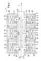
- the reference symbols in FIG. 4 have the same meaning as in the other figures.
- the Stator 4 three identically designed bearing points 5, which with respect to the axial Direction are arranged one behind the other.
- Is between two adjacent bearings 5 a permanent magnet 7 is provided, which is arranged such that that he has the two facing legs 52 of the two adjacent bearings 5 contacted.
- Each permanent magnet 7 is as axially magnetized ring disk, which the shaft 2 surrounds symmetrically to the longitudinal axis A.
- the two permanent magnets 7 are axially magnetized in opposite directions.
- the Magnetization of the permanent magnets 7 is indicated by the arrows (without Reference symbols) symbolically indicated in their interior.
- each base part 51 there is an electrical winding 6 in the form of a ring coil radially outside with respect to the bearing disks 3 and the radially outer Boundary surfaces 32 of the bearing disks 3 are arranged opposite one another, that means for each bearing disc 3 there is exactly one coil with an electrical one Winding 6 is provided.
- the main flow 10 is, as in the first embodiment, one Bearing washers 3 through the shaft 2 to one or both of the adjacent ones Bearing plate (s) guided so that with respect to the radial direction between the permanent magnet 7 on the one hand and the shaft 2 on the other hand none separate returns for the main river 10 are required.
- Each permanent magnet 7 is between two neighboring ones Bearing points 5 magnetized in the opposite direction to him permanent magnet 7 arranged axially in advance.
- the electromagnetic bearing device according to the invention can be also use as a linear actuator, especially as a bistable linear Actuator. When used in this way, it serves as a bistable linear actuator the bearing device 1, the shaft 2 between two stable positions to reciprocate with respect to the axial direction. You do for example the control flow 11 by deactivating the electrical Windings to zero, the shaft 2 will be in the axial direction move until z. B. each the left axial boundary surfaces 31st (with regard to the representation in FIGS. 1, 3 and 4) on the facing them Inner surfaces 521 of the legs 52 rest. This is the first stable Position.
Landscapes
- Engineering & Computer Science (AREA)
- General Engineering & Computer Science (AREA)
- Mechanical Engineering (AREA)
- Physics & Mathematics (AREA)
- Electromagnetism (AREA)
- Magnetic Bearings And Hydrostatic Bearings (AREA)
Priority Applications (1)
| Application Number | Priority Date | Filing Date | Title |
|---|---|---|---|
| EP99810129A EP1028262A1 (fr) | 1999-02-12 | 1999-02-12 | Dispositif de palier electromagnétique |
Applications Claiming Priority (1)
| Application Number | Priority Date | Filing Date | Title |
|---|---|---|---|
| EP99810129A EP1028262A1 (fr) | 1999-02-12 | 1999-02-12 | Dispositif de palier electromagnétique |
Publications (1)
| Publication Number | Publication Date |
|---|---|
| EP1028262A1 true EP1028262A1 (fr) | 2000-08-16 |
Family
ID=8242676
Family Applications (1)
| Application Number | Title | Priority Date | Filing Date |
|---|---|---|---|
| EP99810129A Withdrawn EP1028262A1 (fr) | 1999-02-12 | 1999-02-12 | Dispositif de palier electromagnétique |
Country Status (1)
| Country | Link |
|---|---|
| EP (1) | EP1028262A1 (fr) |
Cited By (4)
| Publication number | Priority date | Publication date | Assignee | Title |
|---|---|---|---|---|
| WO2003087602A1 (fr) * | 2002-04-12 | 2003-10-23 | Forschungszentrum Jülich GmbH | Dispositif de guidage magnetique |
| WO2007000405A3 (fr) * | 2005-06-28 | 2007-03-22 | Siemens Ag | Dispositif de support magnetique d'arbre de rotor a guidage radial et reglage axial |
| DE102015102913A1 (de) * | 2015-03-02 | 2016-09-08 | Pfeiffer Vacuum Gmbh | Magnetlager und Verfahren zum kontaktlosen Halten eines Körpers |
| US20170012491A1 (en) * | 2015-07-06 | 2017-01-12 | Levitronix Gmbh | Electromagnetic rotary drive |
Citations (3)
| Publication number | Priority date | Publication date | Assignee | Title |
|---|---|---|---|---|
| FR2486730A1 (fr) * | 1980-07-11 | 1982-01-15 | Messerschmitt Boelkow Blohm | Accumulateur d'energie a volant |
| US4710656A (en) * | 1986-12-03 | 1987-12-01 | Studer Philip A | Spring neutralized magnetic vibration isolator |
| DE4020726A1 (de) * | 1990-06-29 | 1992-01-02 | Marinescu Geb Bikales | Magnetlager |
-
1999
- 1999-02-12 EP EP99810129A patent/EP1028262A1/fr not_active Withdrawn
Patent Citations (3)
| Publication number | Priority date | Publication date | Assignee | Title |
|---|---|---|---|---|
| FR2486730A1 (fr) * | 1980-07-11 | 1982-01-15 | Messerschmitt Boelkow Blohm | Accumulateur d'energie a volant |
| US4710656A (en) * | 1986-12-03 | 1987-12-01 | Studer Philip A | Spring neutralized magnetic vibration isolator |
| DE4020726A1 (de) * | 1990-06-29 | 1992-01-02 | Marinescu Geb Bikales | Magnetlager |
Cited By (7)
| Publication number | Priority date | Publication date | Assignee | Title |
|---|---|---|---|---|
| WO2003087602A1 (fr) * | 2002-04-12 | 2003-10-23 | Forschungszentrum Jülich GmbH | Dispositif de guidage magnetique |
| WO2007000405A3 (fr) * | 2005-06-28 | 2007-03-22 | Siemens Ag | Dispositif de support magnetique d'arbre de rotor a guidage radial et reglage axial |
| US8058758B2 (en) | 2005-06-28 | 2011-11-15 | Siemens Aktiengesellschaft | Apparatus for magnetic bearing of rotor shaft with radial guidance and axial control |
| DE102015102913A1 (de) * | 2015-03-02 | 2016-09-08 | Pfeiffer Vacuum Gmbh | Magnetlager und Verfahren zum kontaktlosen Halten eines Körpers |
| DE102015102913B4 (de) | 2015-03-02 | 2024-03-14 | Pfeiffer Vacuum Gmbh | Magnetlager und Verfahren zum kontaktlosen Halten eines Körpers |
| US20170012491A1 (en) * | 2015-07-06 | 2017-01-12 | Levitronix Gmbh | Electromagnetic rotary drive |
| US10873241B2 (en) * | 2015-07-06 | 2020-12-22 | Levitronix Gmbh | Electromagnetic rotary drive |
Similar Documents
| Publication | Publication Date | Title |
|---|---|---|
| DE3409047C2 (fr) | ||
| DE2213465C3 (de) | Elektromagnetisches Lagerelement | |
| DE102005030139B4 (de) | Vorrichtung zur magnetischen Lagerung einer Rotorwelle mit Radialführung und Axialregelung | |
| DE69501066T2 (de) | Synchronmotor mit im Rotor eingebetteten Permanentmagneten | |
| DE2420814A1 (de) | Magnetisches lagerelement, insbesondere axiallagerung | |
| EP0574960B1 (fr) | Moteur électrique rotatif | |
| EP1313951A1 (fr) | Pompe a vide | |
| DE69311088T2 (de) | Länglicher Drehmomentmotor und denselben aufweisende steuervorrichtung der winkelabweichung | |
| DE102011080796B4 (de) | Axial belastbare Lageranordnung | |
| EP1504201A1 (fr) | Palier magnetique passif a stabilisation dynamique et entrainement | |
| DE4421594A1 (de) | Vorrichtung zur Veränderung der magnetischen Luftspaltinduktion in elektromechanischen Energiewandlern, bei denen der magnetische Widerstand des magnetischen Schließungskreises in der Maschine variabel ist | |
| DE3687690T2 (de) | Verriegelungsdrehmagnet. | |
| DE102005028209B4 (de) | Magnetische Lagereinrichtung einer Rotorwelle gegen einen Stator mit ineinander greifenden Rotorscheibenelementen und Statorscheibenelementen | |
| EP2038983A1 (fr) | Machine synchrone avec paliers magnétiques excités par le rotor | |
| WO2002027205A1 (fr) | Logement de paliers magnetiques | |
| EP4128291B1 (fr) | Actionneur electromagnetique et son utilisation | |
| EP1028262A1 (fr) | Dispositif de palier electromagnétique | |
| DE894281C (de) | Synchronmotor | |
| DE2213447A1 (de) | Magnetische lagerung | |
| DE19781789B4 (de) | Selbststartender bürstenloser Elektromotor | |
| DE10358341B4 (de) | Vorrichtung zum Lagern einer Kühlmittelzuführung für supraleitende Maschinen | |
| EP3583615B1 (fr) | Actionneur linéaire électromagnétique | |
| EP3100342A1 (fr) | Accouplement magnétique, dispositif d'accouplement, et procédé correspondant | |
| DE20211510U1 (de) | Magnetlager | |
| WO2003087602A1 (fr) | Dispositif de guidage magnetique |
Legal Events
| Date | Code | Title | Description |
|---|---|---|---|
| PUAI | Public reference made under article 153(3) epc to a published international application that has entered the european phase |
Free format text: ORIGINAL CODE: 0009012 |
|
| AK | Designated contracting states |
Kind code of ref document: A1 Designated state(s): AT BE CH CY DE DK ES FI FR GB GR IE IT LI LU MC NL PT SE |
|
| AX | Request for extension of the european patent |
Free format text: AL;LT;LV;MK;RO;SI |
|
| AKX | Designation fees paid | ||
| STAA | Information on the status of an ep patent application or granted ep patent |
Free format text: STATUS: THE APPLICATION IS DEEMED TO BE WITHDRAWN |
|
| 18D | Application deemed to be withdrawn |
Effective date: 20010217 |