EP1029493B1 - Dispositif de cuisson - Google Patents
Dispositif de cuisson Download PDFInfo
- Publication number
- EP1029493B1 EP1029493B1 EP00870021A EP00870021A EP1029493B1 EP 1029493 B1 EP1029493 B1 EP 1029493B1 EP 00870021 A EP00870021 A EP 00870021A EP 00870021 A EP00870021 A EP 00870021A EP 1029493 B1 EP1029493 B1 EP 1029493B1
- Authority
- EP
- European Patent Office
- Prior art keywords
- basin
- foam
- cooking
- emulsion
- level
- Prior art date
- Legal status (The legal status is an assumption and is not a legal conclusion. Google has not performed a legal analysis and makes no representation as to the accuracy of the status listed.)
- Expired - Lifetime
Links
- 238000010411 cooking Methods 0.000 title claims abstract description 117
- 239000006260 foam Substances 0.000 claims abstract description 148
- 239000000839 emulsion Substances 0.000 claims abstract description 114
- 239000007788 liquid Substances 0.000 claims abstract description 40
- 238000005192 partition Methods 0.000 claims description 68
- 235000013305 food Nutrition 0.000 claims description 30
- 239000007791 liquid phase Substances 0.000 claims description 23
- 238000010438 heat treatment Methods 0.000 claims description 13
- 239000000463 material Substances 0.000 claims description 7
- 238000001914 filtration Methods 0.000 claims description 5
- 238000007654 immersion Methods 0.000 claims description 2
- 238000000034 method Methods 0.000 claims description 2
- 230000000284 resting effect Effects 0.000 claims description 2
- 230000009466 transformation Effects 0.000 claims description 2
- 238000005485 electric heating Methods 0.000 claims 4
- 239000004519 grease Substances 0.000 description 14
- XLYOFNOQVPJJNP-UHFFFAOYSA-N water Substances O XLYOFNOQVPJJNP-UHFFFAOYSA-N 0.000 description 7
- 239000000779 smoke Substances 0.000 description 6
- 238000000605 extraction Methods 0.000 description 3
- 230000002159 abnormal effect Effects 0.000 description 2
- 230000015572 biosynthetic process Effects 0.000 description 2
- 238000006073 displacement reaction Methods 0.000 description 2
- 238000002156 mixing Methods 0.000 description 2
- 239000012071 phase Substances 0.000 description 2
- 238000000926 separation method Methods 0.000 description 2
- 239000007787 solid Substances 0.000 description 2
- 206010014405 Electrocution Diseases 0.000 description 1
- XAGFODPZIPBFFR-UHFFFAOYSA-N aluminium Chemical compound [Al] XAGFODPZIPBFFR-UHFFFAOYSA-N 0.000 description 1
- 229910052782 aluminium Inorganic materials 0.000 description 1
- 230000004888 barrier function Effects 0.000 description 1
- 238000009833 condensation Methods 0.000 description 1
- 230000005494 condensation Effects 0.000 description 1
- 238000001704 evaporation Methods 0.000 description 1
- 230000008020 evaporation Effects 0.000 description 1
- 238000005187 foaming Methods 0.000 description 1
- 235000015203 fruit juice Nutrition 0.000 description 1
- 235000015094 jam Nutrition 0.000 description 1
- 235000013372 meat Nutrition 0.000 description 1
- 239000008267 milk Substances 0.000 description 1
- 235000013336 milk Nutrition 0.000 description 1
- 210000004080 milk Anatomy 0.000 description 1
- 238000012986 modification Methods 0.000 description 1
- 230000004048 modification Effects 0.000 description 1
- 239000003921 oil Substances 0.000 description 1
- 229910001220 stainless steel Inorganic materials 0.000 description 1
- 239000010935 stainless steel Substances 0.000 description 1
- 239000000725 suspension Substances 0.000 description 1
Images


Classifications
-
- A—HUMAN NECESSITIES
- A47—FURNITURE; DOMESTIC ARTICLES OR APPLIANCES; COFFEE MILLS; SPICE MILLS; SUCTION CLEANERS IN GENERAL
- A47J—KITCHEN EQUIPMENT; COFFEE MILLS; SPICE MILLS; APPARATUS FOR MAKING BEVERAGES
- A47J37/00—Baking; Roasting; Grilling; Frying
- A47J37/12—Deep fat fryers, e.g. for frying fish or chips
- A47J37/1223—Deep fat fryers, e.g. for frying fish or chips with means for filtering the frying liquid
Definitions
- the present invention relates to a cooking or processing appliance.
- thermal by immersion, domestic or semi-industrial including a tank of cooking intended to contain a liquid brought to a temperature suitable for cooking or heat treatment of a food or food liquid causing during cooking or heat treatment above the upper level of the bath liquid, foam or foam or emulsion during cooking or at least during a part thereof, said tank having a bottom, one or more walls lateral, and an extreme upper edge.
- a cooking appliance according to the preamble of claim 1 is known from document US-A-3646882.
- the present invention relates to a domestic or semi-industrial fryer.
- the present invention relates to a cooking appliance comprising a means to reduce the risk of foam or emulsion exceeding a level in the tank, in particular does not overflow out of the tank, and in particular to avoid substantially any risk of foam or emulsion exceeding a level in the tank, in particular does not overflow out of the tank.
- the apparatus according to the invention which is of the type described in the first paragraph of this memory is essentially characterized in that it comprises or is associated with a receiving means receiving foam, foam or emulsion when said foam, foam or emulsion reaches a level higher than a level predetermined in the tank, said foam or foam or emulsion being transformed in liquid in said means, said receiving means guiding the liquid coming from of the transformation of said foam or foam or emulsion into liquid in the tank to a level below the upper level of the liquid phase of the tank, and in that it comprises a means substantially preventing any passage scum, foam or emulsion in the receiving means at a level located below the upper level of the liquid phase.
- said receiving means comprises or has (a) a chamber or channel for receiving foam, foam or emulsion and (b) a wall having at least one orifice located below the edge extreme of the tank to allow the passage of foam, foam or emulsion through said opening in the receiving chamber when said foam, foam or emulsion reaches a level higher than a predetermined level in the tank and / or having an upper edge at least partially located below the edge end of the tank to allow passage by overflow above at at least part of said upper edge of foam, scum or emulsion in the receiving chamber when said foam, foam or emulsion reaches a level above a predetermined level in the tank.
- the apparatus advantageously comprises a means preventing substantially all passage of foam, foam or emulsion in the receiving means below of said predetermined level.
- the receiving chamber or channel has a volume at least equal to 2% of the volume of the tank. Although such volume has already proven to be sufficient to receive foam or emulsion to ensure a level of foam or emulsion below a level predetermined, the volume of the chamber or channel can vary between 2 and 20% of the tank volume. It is clear that chamber volumes of more than 20% of the tank volume is possible to ensure a level of foam or emulsion below a predetermined level.
- the apparatus comprises one or more partition walls or partitions extending into the tank along of one or more side walls thereof, so as to define between said one or more said partition walls and said one or more side walls, one or more chambers receiving foam, foam or emulsion.
- Said wall or walls of separation have (a) on the one hand, at least one orifice located below the edge extreme of the tank to allow the passage of foam, foam or emulsion through said opening in the receiving chamber when said foam, foam or emulsion reaches a level higher than a predetermined level in the tank and / or having an upper edge at least partially located below the edge end of the tank to allow passage by overflow above at at least part of said upper edge of foam, scum or emulsion in the receiving chamber when said foam, foam or emulsion reaches a level above a predetermined level in the tank, and (b) on the other hand, a passage located below the level of the liquid phase and / or an edge defining with the bottom and / or a side wall a passage located below the level of the liquid phase.
- the walls are arranged in the tank to substantially prevent any passage foam, foam or emulsion in the reception room (s) below of said predetermined level.
- the cooking appliance according to the invention is advantageously an appliance comprising or associated with at least one basket intended to contain the food to be cooked, said basket being lowered into the tank for cooking food.
- lowering of the basket in the tank can be manual (possibly via a multi handle functional) or controlled by a motor mechanism.
- the appliance basket cooking door carries at least one or more partition walls arranged so as to define when the basket is lowered into the tank, between the said wall or walls basket and one or more side walls of the tank, one or more chambers of reception of foam, foam or emulsion.
- Said basket wall (s) lowered position have (a) on the one hand, at least one orifice located below the extreme edge of the tank to allow the passage of foam, scum or emulsion through said orifice in the receiving chamber when said foam, foam or emulsion reaches a level higher than a predetermined level in the tank and / or having an upper edge at least partially located below the extreme edge of the tank to allow passage by overflow above at at least part of said upper edge of foam, scum or emulsion in the receiving chamber when said foam, foam or emulsion reaches a level above a predetermined level in the tank, and (b) on the other hand, a passage located below the level of the liquid phase and / or an edge defining with the bottom and / or a side wall a passage located below the level of the liquid phase.
- the basket walls in the lowered position are arranged in the tank to prevent substantially any passage of foam, foam or emulsion in the reception rooms below said predetermined level.
- the basket is an openwork basket having a bottom, one or more lateral faces and an upper edge, said basket carrying along its side or sides one or more walls of partition, the lower edge of which is arranged to extend below the level of the liquid phase when the basket is lowered into the tank and the upper edge of which is arranged to extend above the level of the liquid phase.
- the bedroom reception is defined between the partition wall (s) of the basket and the partition wall (s) sides of the tank, while the basket partition wall (s) in position lowered into the tank are arranged to substantially prevent any passage foam, foam or emulsion in the receiving chamber below the level of the upper edge of the basket partition wall (s).
- the partition wall (s) carried by the basket are distant from the side walls thereof, and advantageously located outside the basket of so as to form an envelope or frame around the basket.
- the side walls of the basket consist of a solid wall whose lower edge is arranged to prevent when the basket is in the lowered position in the tank, substantially any passage of foam, foam or emulsion in the reception below the level of the upper edge of the partition wall of the basket.
- said partition wall is not flat and preferably has a ripple or folds forming a series of channels substantially vertical when the basket is in the lowered position in the tank. These channels ensure better mixing of oil or fat present in the basket at an upper level of the lower edge of the wall (s) of seperation.
- the partition wall (s) and the parts openwork of the basket are made of materials having a substantially same coefficient of expansion.
- the tank has grooves in which slide the side edges of a partition wall or rails along which slide grooves that have the side edges of a partition wall.
- the partition wall is made in a material having a coefficient of thermal expansion at most equal to coefficient of thermal expansion of the tank or of the part of the tank between said rails.
- the grooves or rails each extend along a side wall of the tank over a height ranging from a level below the liquid level at a level above the liquid level, advantageously at a level close to the predetermined level from which a foam, foam or emulsion passes into the reception room.
- the partition wall (s) form a substantially circular frame, rectangular or square supported on the bottom of the tank and / or carried by one or side walls of the tank.
- the apparatus according to the invention comprises a resistance electric placed under or associated with the bottom of the tank and / or an electric resistance placed in the tank.
- the apparatus according to the invention is a fryer, said fryer preferably comprising a basket advantageously with a multi-handle functional and / or a cover (filtering or not, possibly with a porthole) and / or a filtration system.
- the subject of the invention is also a cooking basket for a cooking appliance, especially for fryer.
- This basket according to the invention is an openwork basket having a bottom, one or more lateral faces and an upper edge, said basket bearing along its side or sides one or more partition walls, of which the lower edge is arranged to extend below the level of the liquid phase when the basket is lowered into the tank and whose upper edge is arranged to extend above the level of the liquid phase.
- the reception room is defined between the basket partition wall (s) and the side wall (s) of the tank, while the basket partition wall (s) in the lowered position in the tank are arranged to substantially prevent any passage of foam, foam or emulsion in the receiving chamber below the edge level upper part of the basket partition wall (s).
- the partition wall (s) carried by the basket are distant from the side walls thereof, and advantageously located outside the basket of so as to form an envelope or frame around the basket.
- the side walls of the basket consist of (a) on the one hand, partially of a part openwork facing the bottom (openwork or at least partially openwork) of the basket, and (b) on the other hand, a partition wall facing the upper edge of the basket, said partition wall being arranged to prevent when the basket is in the lowered position in the tank, substantially any passage of foam, foam or emulsion in the receiving chamber below the edge level upper part of the partition wall of the basket.
- said partition wall is not flat and preferably has a ripple or folds forming a series of channels substantially vertical when the basket is in the lowered position in the tank. These channels ensure better mixing of oil or fat present in the basket at an upper level of the lower edge of the wall (s) of seperation.
- the partition wall (s) and the parts openwork of the basket are made of materials having a substantially same coefficient of expansion.
- the invention also relates to a method of cooking food in a bath of oil and / or liquid fat by means of a fryer comprising a cooking containing the oil or grease bath and a submerged electrical resistance in said tank or associated with a wall of the tank, in which the bath is divided by means of at least one wall in a first zone in contact with the resistance electrical or with the wall associated with the electrical resistance and in a second zone heated mainly by heat transfer from oil or fat from the first zone towards the second zone, and in which we cook the food in the first area so that only if foaming or emulsion above a predetermined level, foam or emulsion passes into the second zone where it becomes oil or fat liquid, oil or fat from the second zone then passing into the first area at the bottom.
- the fryer shown by way of example only is a built-in fryer of the known type (see EP-A-0067730).
- This fryer includes: an envelope 1 which can be built into a cabinet 2 or can be supported on a table; a cooking vessel 2, the upper edge 3 of which rests on the casing when said tank is inserted into the casing 1, a heating resistor 4 carried by a control support 5.
- the cooking vessel advantageously has features to indicate the maximum admissible level N1 of oil or grease in the tank and the minimum admissible level N2 of oil or grease in the tank to ensure good cooking.
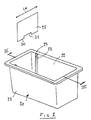
- FIG. 2 shows a cooking tank 20 suitable for replacing the tank 2 of the fryer of Figure 1 to obtain a fryer according to the invention.
- the tank 20 relates to two opposite side walls 21,22 two U-shaped profiles 23 to define between the wings of said profiles of the vertical sliding grooves 24.
- a plate 25 has a width LA arranged so that the lateral edges 26 of the plate slide in the grooves 24 of the profiles. When the plate 25 is placed in the tank 20, this plate divides the tank 20 into two zones 27, 28.
- the upper edge 29 of the plate 25 is located below the edge 3 of the tank but above the level N1, while the lower edge 30 of the plate 25 has a cutout located in below level N2. Said tearing of the plate forms a passage 31 between zone 27 and zone 28.
- the resistor 4 (shown in lines interrupted) is located in zone 27.
- the wall 25 thus divides the tank into a active zone 27 (cooking zone) and a control zone 28.
- foam or an emulsion is formed above the liquid phase.
- foam or emulsion would pass into zone 28 where this foam or emulsion will basically turn into liquid.
- This formation of liquid in zone 28 will cause an oil supply in zone 28 and therefore an oil passage from zone 28 to zone 27 via passage 31.
- zone 27 Since in the embodiment of Figure 3, the resistor 4 is placed in zone 27, the oil contained in zone 28 is not substantially heated only by heat conduction through the wall 25. Zone 28, during cooking normal food (with no foam or emulsion overflow above the edge 29), will be a calm zone not significantly participating in the cooking of food, an area in which no or substantially no vapors are formed. During normal cooking without overflow, the calorific value of the resistance 4 will be used only to cause evaporation of the water contained in food and to reheat the oil or fat present in zone 27.
- zone 27 If a foam or emulsion overflow from zone 27 to zone 28 has place, the passage of oil or fat in a calm state or not agitated (state without formation of foam) by passage 31 towards zone 27 will make it possible to obtain zone 27 a bath still containing enough oil or fat for the cooking and a less agitated bath.
- Figure 15 is a view of a fryer similar to that shown in Figure 3, if it is only that the resistance 4 extends both in zone 27 and in zone 28.
- the resistance 4 passes from zone 28 to zone 27 and vice versa via a passage or a tearing 31 that has the wall 25.
- the wall 25 can advantageously be connected, or even made integral with the resistor, so that the wall 25 then serves support for the resistance ensuring that the latter is spaced from the bottom of the tank 20.
- the wall 25 can also be provided with one or more fingers 200 intended to serve basket stopper when the basket is lowered into the tank.
- Figure 4 shows a plate 40 which can advantageously replace the plate 25 of FIG. 3.
- the plate 40 has a height HA slightly less than the PO depth of the tank, for example 1 to 5 cm less than said depth.
- the plate 40 has a series of cutouts 41 along its lower edge 42 so as to form between the bottom of the tank and the wall 40 a series of passages to transfer oil from zone 28 to zone 27.
- the plate 40 present in its upper part (adjacent part of the edge 44) a series of orifices 45.
- the orifices 45 are located above the level N1, for example at a distance "da" from level N1 sufficient to avoid passage of oil or grease through the orifices 45 due to an increase in the level of the phase oil or fat liquid in the tank caused when the basket is lowered with food to be cooked.
- the distance da is greater than 2 cm, in particular greater than 5 cm.
- the tears 41 advantageously extend below the minimum level of liquid in the tank, for example at a distance "db" from the minimum level which is sufficient to prevent any passage of steam from zone 27 to zone 28 via the cut-outs 41.
- the distance "db" is for example greater than 1 cm.
- FIG. 5 is a view of another tank of a following cooking appliance the invention.
- the tank 50 has rails 54 on two opposite walls 51, 52.
- rectangular plates 55,56 each have a right upper edge 57, a lower edge 58 with cutout 59 and two lateral edges 60 having a groove 61.
- the plate has a length La corresponding substantially to the distance Dc separating the walls 51, 52, the length La however being preferably slightly less than said distance Dc.
- the grooves 61 have a shape marrying substantially the shape of the rails 54.
- the distance Lb separating the bottom of a groove one side edge 60 of a plate at the bottom of the groove the other side edge 60 of said plate is less than the distance Dd between the ends of the rails along from which the gorges slide.
- the height Hb, Hc of the plates can be identical, we have shown in Figure 5 plates 55,56 of different height.
- three zones are created in the tank, namely a first zone 62 located between the plates 55, 56, a second zone 63 located between the wall side of the tank and the plate 56, and a third zone 64 located between the wall side of the tank and the plate 55.
- the zones 63 and 64 are zones in which the food is not cooked and which is intended to collect foam or emulsion produced in zone 62, when the foam or emulsion reaches the level of the upper edge 57 of the plate 56 or the level of the edge upper 57 of plate 55.
- the lower edges and the cutout 59 of the plates 55, 56 are arranged in the tank so as to avoid any passage of water vapors from zone 62 through the teardowns 59 towards zones 63.64.
- the edge grooves sides follow the shape of the rails, it is possible to avoid any passage of steam or emulsion or foam from zone 62 to zone 63 below the level upper of plate 56 and towards zone 64 below the level of the upper edge from plate 55.
- the heating resistor 4 shown in broken lines is advantageously a resistor located in zone 62 in the vicinity of the bottom of the tank.
- this heating element is advantageously located in the part of the bottom located under the part 62.
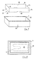
- Figure 7 shows yet another embodiment of a tank of an apparatus Cooking.
- a frame or envelope 81 formed by four substantially vertical walls 82,83,84,85 connected between them.
- the walls have an upper edge 86 and a lower edge 87 intended to rest on the bottom of the tank.
- the walls 82 and 84 show the along their lower edge a cutout 88 intended to form a passage for oil or liquid fat, while forming a barrier to the passage of vapors, foam or emulsion.
- a first zone 89 is formed central in which the food is fried, and a second zone 90 located between the side walls of the tank 80 and the walls of the frame, said second zone being intended to receive foam or emulsion of oil or grease when the level foam or emulsion exceeds a predetermined level defined by the level upper edges 86 of the walls.
- This predetermined level is for example chosen to allow the transfer of foam or emulsion only when cooking abnormal.
- the level of the upper edges 86 is 3 to 6 cm in above the level of the upper edge of the tank or of the notch 92 possibly provided in the tank to receive a removable element carrying the basket or the electrical resistance 4.
- the electrical resistance 4 is advantageously plunged in the oil or grease bath of zone 89. (see figure 8)
- FIG. 9 shows yet another embodiment of a cooking vessel.
- This tank 100 comprises along its upper edge 101 an L-shaped profile 102 so as to define along said upper edge 101 a receiving channel 103.
- the outer edge 104 of the profile 102 is at a level N5 higher than the level N6 of the edge 101.
- Two cutouts 105 are shaped below the edge 101 so as to form passages.
- the tank 100 also has two conduits 106 each extending from a lower opening 107 adjacent the bottom 108 of the tank to an upper opening 109 extending at an adjacent level from the level N6 of the upper edge 101.
- Each cutout 105 forms thus a passage between the channel 103 and the interior space 110 of a conduit 106.
- the foam or emulsion When cooking where an excessive amount of foam or emulsion is produced, as soon as the level of foam or emulsion exceeds the level N6, the foam or emulsion overflows above the upper edge 101 to penetrate into the channel 103. In the channel 103, the said foam or emulsion becomes a liquid phase and flows towards the cutouts 105 before entering the conduits 106. The conduits 106 then guide the foam or emulsion transformed into liquid towards the phase liquid from the bath liquid from the tank. The conduits 106 make it possible to avoid any passage of foam or emulsion therein, as long as the level of foam or emulsion has not exceeded the level N6.
- the heating resistor 4 shown in broken lines is advantageously a resistor immersed in the tank 100.
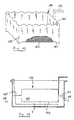
- FIG 11 shows in perspective a basket according to the invention.
- This basket 120 has a handle 123, a perforated bottom 121 and side walls 122 made by means of a full corrugated sheet These walls 122 have a lower edge 124 adjacent to the openwork bottom 121 and an upper edge 125.
- the height of the sheet 122 is for example between 3 and 10 cm.
- the lower edge 124 is arranged to immerse in the liquid phase of the cooking bath, at a level corresponding to level N9 from the bottom 121 of the basket or below said level.
- the bottom edge 124 is below the minimum level N2 of oil or grease in the tank 2, while the upper edge 125 is arranged to extend above the level maximum of N1 oil in tank 2, for example at a distance from said level N1 corresponding to the maximum authorized height of foam or emulsion in the tank 2.
- the sheet 122 thus divides the cooking bath and the tank into two zones, namely a cooking area 126 corresponding to the interior volume of the basket, and a zone 127 extending between the sheet 122 and the side walls of the tank 2.
- the area 127 is a slightly agitated area which does not receive substantially any foam or cooking emulsion passing below the lower edge 124 of the sheet 122.
- the foam or the emulsion passes over the edge 125 to fall into the zone 127, where this foam or emulsion becomes a liquid phase.
- the sheet 122 is advantageously corrugated so as to limit the contact of the food with said sheet and to form substantially vertical channels 128 ensuring good circulation of oil or liquid fat around the food present in the basket, in particular along the face of the sheet facing the interior of the basket (126). This circulation is obtained essentially by convection.
- the walls 122 may have extensions 129 forming legs resting on the bottom of the tank.
- Such legs 129 are shown in broken lines in Figure 11. These legs extend for example to the four lower corners of the basket.
- FIG 13 shows another embodiment of a basket according to the invention.
- the basket includes an element 150 intended to contain the food to be cooked and produced by means of a trellis carried by a bent rod 151 forming the upper edge of said element.
- a frame 152 produced by means of a folded solid sheet is associated with a handle 153.
- the frame 152 carries on two opposite walls 154,155 two legs 156 turned towards one another and having a part 157 curved upwards.
- the part 157 has a free end 158 advantageously not attached to the frame.
- the element 150 present in its part produced by means of said trellis and below of the rod 151, two windows 159 each intended to allow passage to a leg 156 of the frame 152.
- the part of the rod 151 situated above the window 159 is supported on the leg 156, the curved part 157 serving as a fixing means (clip type for example) preventing unwanted detachment of the element legs (i.e. the displacement of the part of the rod out of the curved part of the paw).
- the shape of the curved parts of the legs allows a slight relative displacement X of the rod and therefore of the perforated element 150 relative to the frame 152. This thus makes it possible, when shaking the basket via the handle 153 in the direction Y of ensuring a relative movement X of the element with respect to the frame 152 and therefore better drainage of oil or fat present on food cooked.
- the lower edge 160 of the frame 152 is immersed in the liquid phase of the oil or grease bath, while the edge upper 161 extends above the level of the liquid phase, for example at maximum level of foam or emulsion considered admissible for the tank 2.
- foam or emulsion in zone 170 located inside the frame exceeds a level N8 considered admissible (level of the upper edge 161 of the frame)
- foam or emulsion passes into the slightly agitated area 171 located between the frame 152 and the side walls of the tank 2.
- This foam or emulsion is then transforms into a liquid phase and oil or fat from area 171 passes under the lower edge 160 of the frame to enter zone 170.
- the lower edge 160 may be located above the level N10 of the bottom of element 150.
- the lower edge 160 of the basket frame lowered in the tank is below the minimum level of oil or grease required for the tank (N1).
- the maximum level to which the target extends or may extend lower edge will be chosen to avoid any passage of steam or foam from the cooking zone (170) under the lower edge 160 of the frame 152 towards the zone 171, this maximum level will be all the higher as the walls 152 are separated from the element 150.
- a wall 173 of the frame 152 preferably a wall substantially parallel to the direction Y in which the handle 153 extends, an extension 174 intended to guide the cooked food out of the element 150 towards a container or a dish (for example during a tilting or pivoting P of the element 150 relative to an axis parallel to the direction Y or to the handle).
- the height of the wall (s) of separation 25,56,57,86,106,122,152
- the level to which the upper edge thereof above which an overflow of foam or emulsion is possible or the level of the overflow orifices of foam or emulsion, as well as the volume of the receiving chamber depend the flow of foam, emulsion which must be absorbed by the receiving chamber during abnormal cooking to ensure that the level of foam or emulsion in the tank remains below a maximum permissible level of foam in the tank, for example example when cooking an excessive amount of food.
- the flow of foam or emulsion produced in the cooking zone and suitable for overflow is variable for each device.
- This flow will depend on the volume of the tank, the amount of oil or fat present in the tank, the amount of food that can be processed during a cooking cycle, thermal power heating resistance, air temperature above the foam, or emulsion, the temperature of the tank walls and the partition walls, material used, etc.
- the flow of foam or emulsion capable of passing from the zone of cooking to the slightly agitated area will be all the less as the amount of foam or emulsion turning into liquid in the cooking zone is important.
- the height or level of the upper edge or the overflow passages dividing walls in the tank is advantageously not too low to avoid that a quantity of self-controlling foam or emulsion produced during a normal cooking does not overflow in the slightly agitated area, and to avoid a possible risk of saturation of the area which is not very agitated by foam or emulsion from the cooking zone.
- Said height or level of the upper edge, or even the passage section of the orifices (45) will therefore be advantageously determined to limit, preferably avoid, any passage of foam or emulsion in the slightly agitated zone for normal cooking, i.e. to limit, or even avoid any passage of foam or emulsion which could be self-controlled by the height of the walls of the tank, the temperature of the walls, the temperature of the air located above the foam or emulsion.
- the cooking appliance may consist only of a tank of cooking as shown in Figures 2 to 13, tank intended to be placed on a heating element, for example on an electric plate or a plate gas heating.
- the apparatus according to the invention comprises preferably a heating system such as an electrical resistance.
- the latter is preferably a resistance immersed in the cooking bath, resistance found in the cooking zone (126) and / or in the slightly agitated zone (127), of preferably substantially only in the cooking zone.
- tanks with associated bottom or resistance heating on the outside of the tank.
- the apparatus according to the invention may include a cover, a filter cover, a smoke extraction system, a smoke treatment system, a smoke condensation, a basket ordered, a basket with multi handle functional, an automatic basket lowering and / or lifting system, etc.
- Partition walls instead of being vertical or substantially vertical can be tilted. For example, they may have an inclination such as its lower edge is more adjacent to a side wall than is its upper edge.
- the cooking appliance according to the invention makes it possible to fry various foods (fries, croquettes, breaded meat, etc.), but also allows the cooking of liquid or suspension (milk, fruit juice, jam) forming a foam or foam when cooking.
Landscapes
- Engineering & Computer Science (AREA)
- Food Science & Technology (AREA)
- Frying-Pans Or Fryers (AREA)
- Control And Other Processes For Unpacking Of Materials (AREA)
- General Preparation And Processing Of Foods (AREA)
- Cookers (AREA)
Description
D'autre part, lorsque de la mousse ou émulsion eau/vapeur-huile ou graisse vient à déborder hors de la cuve, des dangers de brûlure, de court circuits, d'électrocution, d'hygiène, d'incendie peuvent être créés. Ces dangers sont dus au fait que de l'huile, de la graisse et de l'eau viennent se déposer sur des parois extérieures de l'enveloppe entourant la cuve et/ou viennent à pénétrer dans l'espace situé entre l'enveloppe extérieure de la friteuse et la cuve et/ou viennent à toucher un support amovible étanche portant le panier ou la résistance et qui est destiné à être logé dans une ouverture de la cuve et de l'enveloppe et/ou viennent à pénétrer dans des contacts électriques et/ou viennent à rentrer dans le filtre ou dans le système d'aspiration des fumées.
- la figure 1 est une vue en perspective d'une friteuse encastrable du type connu;
- la figure 2 est une vue en perspective d'une cuve de cuisson;
- la figure 3 est une vue en coupe selon la ligne III-III de la cuve de la figure 2 après placement de la paroi de séparation;
- la figure 4 est une vue d'une autre paroi de séparation qui peut être utilisée pour la cuve de la figure 2;
- la figure 5 est une vue d'une autre cuve de cuisson similaire à celle de la figure 2;
- la figure 6 est une vue en coupe selon les lignes VI-VI de la cuve de la figure 5 après placement des parois de séparation;
- la figure 7 est une vue en perspective éclatée d'une autre cuve de cuisson;
- la figure 8 est une vue de dessus de la cuve de la figure 7 après placement des parois de séparation;
- la figure 9 est une vue en perspective d'une autre cuve de cuisson;
- la figure 10 est une vue en coupe selon la ligne X-X de la cuve de la figure 9;
- la figure 11 est une vue en perspective d'un panier suivant l'invention;
- la figure 12 est une vue en coupe d'une friteuse munie du panier de la figure 11;
- la figure 13 est une vue en perspective d'un autre panier suivant l'invention;
- la figure 14 est une vue en coupe d'une friteuse munie du panier de la figure 13;
- la figure 15 est une vue d'une friteuse similaire à celle représentée à la figure 3.
Lors d'une cuisson où une quantité excessive de mousse ou d'émulsion est produite, dès que le niveau de mousse u d'émulsion dépasse le niveau N6, de la mousse ou de l'émulsion déborde au-dessus du bord supérieur 101 pour pénétrer dans le canal 103. Dans le canal 103, ladite mousse ou émulsion se transforme en une phase liquide et coule vers les découpes 105 avant de pénétrer dans les conduits 106. Les conduits 106 guident alors la mousse ou émulsion transformée en liquide vers la phase liquide du bain liquide de la cuve. Les conduits 106 permettent d'éviter tout passage de mousse ou d'émulsion dans ceux-ci, tant que le niveau de mousse ou d'émulsion n'a pas dépassé le niveau N6.
Pour favoriser l'écoulement d'huile ou de graisse dans le canal 103 vers les découpes 105, il peut être utile de prévoir que le fond 103b du canal 103 présente au moins partiellement une pente.
La résistance chauffante 4 montrée en traits interrompus est avantageusement une résistance plongeant dans la cuve 100.
La zone 127 est une zone peu agitée qui ne reçoit sensiblement pas de mousse ou d'émulsion de cuisson passant en dessous du bord inférieur 124 de la tôle 122. Ainsi, lorsque le niveau de mousse ou d'émulsion dépasse le niveau du bord supérieur 125 de la tôle 122, de la mousse ou de l'émulsion passe au-dessus du bord 125 pour tomber dans la zone 127, où cette mousse ou émulsion se transforme en une phase liquide. Lors du passage de mousse ou d'émulsion au-dessus du bord 125, de l'huile ou de la graisse passe en dessous du bord 124 de la tôle de la zone 127 vers la zone 126.
La tôle 122 est avantageusement ondulée de manière à limiter le contact des aliments avec ladite tôle et pour former des canaux 128 sensiblement verticaux assurant une bonne circulation d'huile ou de graisse liquide autour des aliments présents dans le panier, en particulier le long de la face de la tôle tournée vers l'intérieur du panier (126). Cette circulation est obtenue essentiellement par convection.
Claims (17)
- Appareil de cuisson ou de traitement thermique par immersion, domestique ou semi-industriel comprenant une cuve de cuisson (20,50,80,100) destinée à contenir un liquide de cuisson pour la cuisson d'un aliment formant au-dessus du niveau supérieur d'une phase ou bain liquide, une mousse ou une écume ou une émulsion lors de la cuisson ou au moins lors d'une partie de celle-ci, ladite cuve présentant un fond, une ou des parois latérales, et un bord extrême supérieur, ladite cuve présentant une marque (N1) correspondant au niveau maximal de liquide de cuisson dans 1a cuve et étant associée à un moyen définissant dans la cuve une zone de cuisson d'aliments et une zone de non cuisson d'aliments, ainsi qu'un passage entre la zone de cuisson et la zone de non cuisson situé en dessous du niveau maximal (N1) de liquide de cuisson dans la cuve, caractérisé en ce qu'il comporte ou est associé à un moyen (25; 40, 55, 56, 81, 101,106,120, 122b,152) définissant une zone de non cuisson dans la cuve et permettant le passage de mousse, d'écume ou d'émulsion de la zone de cuisson dans la zone de non cuisson lorsque ladite mousse, écume ou émulsion atteint un niveau supérieur à un niveau prédéterminé (N3; 57; 86; N6; 125; 161) dans la cuve qui se trouve au moins 2 centimètres, de préférence au moins 5 centimètres au dessus du niveau maximal (N1) de liquide de cuisson dans la cuve, ladite mousse ou écume ou émulsion étant transformée en liquide dans la zone de non cuisson (28; 63,64; 90; 103,110; 127; 171), ledit moyen (25;56,57; 81; 106; 122b; 152) empêchant sensiblement tout passage d'écume, de mousse ou d'émulsion dans ladite zone de non cuisson (28; 63,64; 90; 103,110; 127; 171) à un niveau situé en dessous dudit niveau prédéterminé (N3; 57; 86; N6; 125; 161), et en ce qu'il comporte un moyen guidant ledit liquide provenant de la transformation de ladite mousse ou écume ou émulsion dans la cuve jusqu'à un niveau (31;59; 88; 107; 124;160) situé en dessous du niveau maximum (N1) de liquide de cuisson de la cuve.
- Appareil suivant la revendication 1, caractérisé en ce que ledit moyen définissant une zone de non cuisson dans la cuve et permettant le passage de mousse, d'écume ou d'émulsion de la zone de cuisson dans la zone de non cuisson comporte une paroi (25;56,57; 81; 106; 122b; 152) présentant au moins un orifice (45) situé en dessous du bord extrême (3) de la cuve pour permettre le passage de mousse, d'écume ou d'émulsion par ledit orifice (45) dans la zone de non cuisson lorsque ladite mousse, écume ou émulsion atteint un niveau prédéterminé correspondant au niveau dudit orifice (45) dans la cuve et/ou présentant un bord supérieur (29; 57; 86; 101; 125; 161) au moins partiellement situé en dessous du bord extrême (3,104) de la cuve pour permettre le passage par débordement au-dessus d'au moins une partie dudit bord supérieur (29; 57; 86; 101; 125; 161) de mousse, d'écume ou d'émulsion dans la zone de non cuisson lorsque ladite mousse, écume ou émulsion atteint un niveau supérieur audit niveau prédéterminé (N3; 57; 86; N6; 125; 161) dans la cuve, et en ce que ladite paroi est agencée dans la cuve pour empêcher sensiblement tout passage d'écume, de mousse ou d'émulsion dans la zone de non cuisson en dessous dudit niveau prédéterminé (N3; 57; 86; N6; 125; 161).
- Appareil suivant 1a revendication 1 ou 2, caractérisé en ce que la zone de non cuisson présente un volume au moins égal à 2% du volume de la cuve.
- Appareil suivant l'une quelconque des revendications précédentes, caractérisé en ce qu'il comporte une ou plusieurs parois de séparation (25;56,57; 81; 106; 122b; 152) s'étendant dans la cuve le long d'une ou de parois latérales de celle-ci, de manière à définir entre ladite ou lesdites parois de séparation et ladite ou lesdites parois latérales de 1a cuve, une ou plusieurs zones de non cuisson pour réceptionner (28; 63,64; 90; 103,110; 127; 171) de la mousse, de l'écume ou de l'émulsion de la zone de cuisson, ladite ou lesdites parois de séparation (25;56,57; 81; 106; 122b; 152) présentant, d'une part,en ce que la ou les parois (25;56,57; 81; 106; 122b; 152) sont agencées dans la cuve pour empêcher sensiblement tout passage d'écume, de mousse ou d'émulsion dans la ou les zones de non cuisson en dessous dudit niveau prédéterminé (N3; 45 ; 57; 86; N6; 125; 161).au moins un orifice (45) situé en dessous du bord extrême de la cuve, mais au dessus dudit niveau prédéterminé pour permettre le passage de mousse, d'écume ou d'émulsion par ledit orifice (45) dans la chambre de réception lorsque ladite mousse, écume ou émulsion atteint un niveau supérieur audit niveau prédéterminé dans la cuve et/ou présentant un bord supérieur (29; 57; 86; 101; 125; 161) au moins partiellement situé en dessous du bord extrême de la cuve, mais au dessus dudit niveau prédéterminé (N3; 57; 86; N6; 125; 161) pour permettre le passage par débordement au-dessus d'au moins une partie dudit bord supérieur (29; 57; 86; 101; 125; 161) de mousse, d'écume ou d'émulsion dans la chambre de réception lorsque ladite mousse, écume ou émulsion atteint un niveau supérieur audit niveau prédéterminé (N3; 57; 86; N6; 125; 161) dans la cuve, et, d'autre part,un passage (31,41,88,107) situé sous le niveau minimal (N2) de phase liquide dans la cuve et/ou un bord (124,160) définissant avec le fond et/ou une paroi latérale un passage situé sous le niveau minimal (N2) de la phase liquide dans la cuve, et
- Appareil de cuisson suivant l'une quelconque des revendications précédentes, ledit appareil comprenant au moins un panier destiné à contenir les aliments à cuire, ledit panier étant abaissé dans la cuve pour la cuisson des aliments, caractérisé en ce que le panier porte au moins une ou des parois (122;152) de séparation agencées de manière à définir lorsque le panier est abaissé dans la cuve, entre ladite ou lesdites parois du panier et une ou des parois latérales de la cuve, une ou plusieurs chambres de réception (127;171) de mousse, d'écume ou d'émulsion, ladite ou lesdites parois (122;152) du panier en position abaissée présentant, d'une part,en ce que la ou les parois (122;152) du panier en position abaissée sont agencées dans la cuve pour empêcher sensiblement tout passage d'écume, de mousse ou d'émulsion dans la ou les chambres de réception (127;171) en dessous dudit niveau prédéterminé (N8,125,161).au moins un orifice situé en dessous du bord extrême de la cuve pour permettre 1e passage de mousse, d'écume ou d'émulsion par ledit orifice dans la chambre de réception lorsque ladite mousse, écume ou émulsion atteint un niveau supérieur audit niveau prédéterminé (N8; 125; 161) dans 1a cuve et/ou présentant un bord supérieur (125;161) au moins partiellement situé en dessous du bord extrême de la cuve mais supérieur d'au moins 2 centimètres, de préférence d'au moins 5 centimètres du niveau maximal (N1) de liquide de cuisson dans la cuve pour permettre le passage par débordement au-dessus d'au moins une partie dudit bord supérieur (125,161) de mousse, d'écume ou d'émulsion dans la chambre de réception (127;171) lorsque ladite mousse, écume ou émulsion atteint un niveau supérieur audit niveau prédéterminé (N8,125,161) dans la cuve, et, d'autre part,un passage situé sous le niveau minimal (N2) de la phase liquide lorsque le panier est en position abaissée dans la cuve et/ou un bord (124,160) définissant avec le fond et/ou une paroi latérale un passage situé sous le niveau minimal (N2) de la phase liquide lorsque le panier est en position abaissée dans la cuve, et
- Appareil de cuisson suivant la revendication 5, caractérisé en ce que 1e panier est un panier ajouré présentant un fond, une ou des faces latérales et un bord supérieur, ledit panier portant le long de sa ou de ses faces latérales une ou des parois de séparation (122,152), dont le bord inférieur (124,160) est agencé pour s'étendre sous le niveau minimal (N2) de la phase liquide lorsque le panier est abaissé dans la cuve et dont le bord supérieur (125,161) est agencé pour s'étendre au moins 2 centimètres, de préférence au moins 5 centimètres au dessus du niveau maximal (N1) de liquide de cuisson dans la cuve lorsque le panier est en position abaissée dans la cuve, en ce que la chambre de réception (127,171) est définie entre la ou les parois de séparation (122,152) du panier et la ou les parois latérales de la cuve, et en ce que la ou les parois de séparation (122,152) du panier en position abaissée dans la cuve sont agencées pour empêcher sensiblement tout passage d'écume, de mousse ou d'émulsion dans la chambre de réception (127,171) en dessous du niveau du bord supérieur (125,161) de la ou des parois de séparation du panier en position abaissée du panier.
- Appareil de cuisson suivant la revendication 6, caractérisé en ce que la ou les parois de séparation (152) portées par le panier ajouré (150) sont distantes des parois latérales de celui-ci, et avantageusement situées à l'extérieur du panier de manière à former une enveloppe ou cadre (152) autour du panier ajouré (150).
- Appareil de cuisson suivant la revendication 6, caractérisé en ce que la ou les parois latérales du panier sont constituées d'une paroi pleine dont le bord inférieur (124) est agencé pour empêcher lorsque le panier est en position abaissée dans la cuve, sensiblement tout passage d'écume, de mousse ou d'émulsion dans la chambre de réception en dessous du niveau du bord supérieur (125) de la paroi du panier.
- Appareil de cuisson suivant la revendication 7 ou 8, caractérisé en ce que ladite paroi (122b) présente une ondulation ou des plis formant une série de canaux sensiblement verticaux lorsque le panier est en position abaissée dans la cuve.
- Appareil de cuisson suivant l'une quelconque des revendications 6 à 9, caractérisé en ce que la ou les parois de séparation et les parties ajourées du panier sont réalisées en des matériaux présentant sensiblement un même coefficient de dilatation.
- Appareil suivant l'une quelconque des revendications 1 à 5, caractérisé en ce que 1a cuve présente des gorges (24) dans lesquelles coulissent les bords latéraux d'une paroi de séparation (25;40) ou des rails (54) le long desquels coulissent des gorges (61) que présentent les bords latéraux d'une paroi de séparation (55,56).
- Appareil suivant la revendication 11, caractérisé en ce que la paroi de séparation est réalisée en un matériau présentant un coefficient de dilatation thermique au plus égal au coefficient de dilatation thermique de la cuve ou de la partie de la cuve située entre lesdits rails.
- Appareil suivant la revendication 11 ou 12, caractérisé en ce que les gorges ou les rails (24,54) s'étendent chacun le long d'une paroi latérale de la cuve sur une hauteur allant d'un niveau situé sous le niveau minimal de liquide dans la cuve (N2) à un niveau situé au-dessus du niveau maximal (N1) de liquide dans la cuve, avantageusement à un niveau proche du niveau prédéterminé à partir duquel une mousse, une écume ou une émulsion passe dans la chambre de réception de la mousse, écume ou émulsion provenant de la zone de cuisson.
- Appareil de cuisson suivant l'une quelconque des revendications 1 à 5, caractérisé en ce que la ou les parois de séparation forment un cadre (81) sensiblement circulaire, rectangulaire ou carré prenant appui sur le fond de la cuve et/ou porté par une ou des parois latérales de la cuve.
- Appareil de cuisson suivant l'une quelconque des revendications précédentes, caractérisé en ce qu'il comporte une résistance électrique placée sous ou associée au fond de la cuve et/ou une résistance électrique (4) placée dans la cuve.
- Appareil de cuisson suivant l'une quelconque des revendications précédentes, caractérisé en que ledit appareil est une friteuse, ladite friteuse comportant de préférence un panier avantageusement avec poignée multi fonctionnelle et/ou un couvercle et/ou un système de filtration.
- Procédé de cuisson d'aliments dans un bain d'huile et/ou de graisse liquide au moyen d'une friteuse suivant la revendication 16, dans lequel on divise le bain au moyen d'une paroi en une zone de cuisson dans laquelle le bain liquide est en contact avec la résistance électrique ou avec 1a paroi associée à la résistance électrique et en une zone de non cuisson chauffée essentiellement par transfert de chaleur de l'huile de la zone de cuisson vers la zone de non cuisson, et dans lequel on cuit les aliments dans la zone de cuisson de manière à ce qu'uniquement en cas de formation de mousse ou d'émulsion au-dessus d'un niveau prédéterminé, de la mousse ou de l'émulsion passe dans la zone de non cuisson où elle se transforme sous forme d'huile ou de graisse liquide, de l'huile ou de la graisse de la zone de non cuisson passant alors dans la zone de cuisson.
Applications Claiming Priority (2)
| Application Number | Priority Date | Filing Date | Title |
|---|---|---|---|
| BE9900113A BE1012477A7 (fr) | 1999-02-19 | 1999-02-19 | Appareil de cuisson. |
| BE9900113 | 1999-02-19 |
Publications (2)
| Publication Number | Publication Date |
|---|---|
| EP1029493A1 EP1029493A1 (fr) | 2000-08-23 |
| EP1029493B1 true EP1029493B1 (fr) | 2002-07-31 |
Family
ID=3891769
Family Applications (1)
| Application Number | Title | Priority Date | Filing Date |
|---|---|---|---|
| EP00870021A Expired - Lifetime EP1029493B1 (fr) | 1999-02-19 | 2000-02-16 | Dispositif de cuisson |
Country Status (4)
| Country | Link |
|---|---|
| EP (1) | EP1029493B1 (fr) |
| AT (1) | ATE221333T1 (fr) |
| BE (1) | BE1012477A7 (fr) |
| DE (1) | DE60000291T2 (fr) |
Families Citing this family (2)
| Publication number | Priority date | Publication date | Assignee | Title |
|---|---|---|---|---|
| BE1013920A6 (fr) * | 2001-01-17 | 2002-12-03 | Ariam S P R L | Appareil de cuisson. |
| CN118266756A (zh) * | 2022-12-30 | 2024-07-02 | 佛山市顺德区美的电热电器制造有限公司 | 烹饪器具 |
Family Cites Families (6)
| Publication number | Priority date | Publication date | Assignee | Title |
|---|---|---|---|---|
| US3646882A (en) * | 1969-05-28 | 1972-03-07 | Richard T Keating | Filter for deep fryer |
| US3933645A (en) * | 1974-07-08 | 1976-01-20 | Keramidas John D | Deep fat fryer trap |
| FR2507398B1 (fr) | 1981-06-04 | 1983-11-18 | Dietrich & Cie De | |
| DE3542909A1 (de) * | 1985-12-04 | 1987-06-11 | Bosch Siemens Hausgeraete | Fritiergeraet |
| US5452648A (en) * | 1993-10-21 | 1995-09-26 | Hobart Corporation | Screen box for a pasta cooker |
| US5629039A (en) * | 1995-06-08 | 1997-05-13 | Ventura Foods, Llc | Cooking oil extending process |
-
1999
- 1999-02-19 BE BE9900113A patent/BE1012477A7/fr not_active IP Right Cessation
-
2000
- 2000-02-16 AT AT00870021T patent/ATE221333T1/de not_active IP Right Cessation
- 2000-02-16 EP EP00870021A patent/EP1029493B1/fr not_active Expired - Lifetime
- 2000-02-16 DE DE60000291T patent/DE60000291T2/de not_active Expired - Fee Related
Also Published As
| Publication number | Publication date |
|---|---|
| DE60000291T2 (de) | 2003-03-20 |
| DE60000291D1 (de) | 2002-09-05 |
| ATE221333T1 (de) | 2002-08-15 |
| EP1029493A1 (fr) | 2000-08-23 |
| BE1012477A7 (fr) | 2000-11-07 |
Similar Documents
| Publication | Publication Date | Title |
|---|---|---|
| EP1057437B1 (fr) | Appareil culinaire électrique multi-fonctions | |
| US6260478B1 (en) | Heat distribution system for a grill | |
| US7415922B2 (en) | Grill pan | |
| EP0818168B1 (fr) | Appareil de cuisson comportant une plaque et un récipient de cuisson | |
| US20060289452A1 (en) | Reversible grill with differing tilt angles | |
| EP1029493B1 (fr) | Dispositif de cuisson | |
| CA2980219A1 (fr) | Accessoire de cuisson et appareil electrique de cuisson comportant un accessoire de cuisson | |
| EP1792555B1 (fr) | Appareil de cuisson | |
| EP0532425B1 (fr) | Appareil électrique de cuisson, notamment pour la viande | |
| EP1444938B1 (fr) | Unité gril et appareil de cuisson avec la même | |
| US20040187704A1 (en) | Multi-purpose steamer/smoker and grilling devices | |
| EP1332704A2 (fr) | Friteuse électrique | |
| US20200337500A1 (en) | Cooking vessel with an opening for drainage | |
| EP3135163B1 (fr) | Appareil polyvalent électrique pour la cuisson d'aliments | |
| FR2682273A3 (en) | Utensil for performing a variety of cooking tasks | |
| KR200366775Y1 (ko) | 전기로스타에 탈부착이 가능한 열반사판 | |
| BE1009202A6 (fr) | Panier pour appareil de cuisson. | |
| EP0039631B1 (fr) | Appareil de cuisson portatif | |
| FR2701201A1 (fr) | Dispositif pyramidal adaptable à tout foyer pour griller sainement divers sandwichs chauds. | |
| EP0811346A1 (fr) | Appareil de cuisson de table à utilisations multiples | |
| EP1224896A1 (fr) | Appareil de cuisson | |
| KR20240146234A (ko) | 다용도 조리기기 | |
| FR2481590A1 (fr) | Appareil de cuisson portatif | |
| FR2703576A1 (fr) | Grille-pain. | |
| JP3018728U (ja) | 魚焼き器 |
Legal Events
| Date | Code | Title | Description |
|---|---|---|---|
| PUAI | Public reference made under article 153(3) epc to a published international application that has entered the european phase |
Free format text: ORIGINAL CODE: 0009012 |
|
| AK | Designated contracting states |
Kind code of ref document: A1 Designated state(s): AT BE CH CY DE DK ES FI FR GB GR IE IT LI LU MC NL PT SE |
|
| AX | Request for extension of the european patent |
Free format text: AL;LT;LV;MK;RO;SI |
|
| 17P | Request for examination filed |
Effective date: 20010206 |
|
| AKX | Designation fees paid |
Free format text: AT BE CH CY DE DK ES FI FR GB GR IE IT LI LU MC NL PT SE |
|
| 17Q | First examination report despatched |
Effective date: 20010405 |
|
| GRAG | Despatch of communication of intention to grant |
Free format text: ORIGINAL CODE: EPIDOS AGRA |
|
| GRAG | Despatch of communication of intention to grant |
Free format text: ORIGINAL CODE: EPIDOS AGRA |
|
| GRAH | Despatch of communication of intention to grant a patent |
Free format text: ORIGINAL CODE: EPIDOS IGRA |
|
| GRAH | Despatch of communication of intention to grant a patent |
Free format text: ORIGINAL CODE: EPIDOS IGRA |
|
| GRAA | (expected) grant |
Free format text: ORIGINAL CODE: 0009210 |
|
| AK | Designated contracting states |
Kind code of ref document: B1 Designated state(s): AT BE CH CY DE DK ES FI FR GB GR IE IT LI LU MC NL PT SE |
|
| PG25 | Lapsed in a contracting state [announced via postgrant information from national office to epo] |
Ref country code: IT Free format text: LAPSE BECAUSE OF FAILURE TO SUBMIT A TRANSLATION OF THE DESCRIPTION OR TO PAY THE FEE WITHIN THE PRESCRIBED TIME-LIMIT;WARNING: LAPSES OF ITALIAN PATENTS WITH EFFECTIVE DATE BEFORE 2007 MAY HAVE OCCURRED AT ANY TIME BEFORE 2007. THE CORRECT EFFECTIVE DATE MAY BE DIFFERENT FROM THE ONE RECORDED. Effective date: 20020731 Ref country code: IE Free format text: LAPSE BECAUSE OF FAILURE TO SUBMIT A TRANSLATION OF THE DESCRIPTION OR TO PAY THE FEE WITHIN THE PRESCRIBED TIME-LIMIT Effective date: 20020731 Ref country code: GR Free format text: LAPSE BECAUSE OF FAILURE TO SUBMIT A TRANSLATION OF THE DESCRIPTION OR TO PAY THE FEE WITHIN THE PRESCRIBED TIME-LIMIT Effective date: 20020731 Ref country code: FI Free format text: LAPSE BECAUSE OF FAILURE TO SUBMIT A TRANSLATION OF THE DESCRIPTION OR TO PAY THE FEE WITHIN THE PRESCRIBED TIME-LIMIT Effective date: 20020731 Ref country code: AT Free format text: LAPSE BECAUSE OF FAILURE TO SUBMIT A TRANSLATION OF THE DESCRIPTION OR TO PAY THE FEE WITHIN THE PRESCRIBED TIME-LIMIT Effective date: 20020731 |
|
| REF | Corresponds to: |
Ref document number: 221333 Country of ref document: AT Date of ref document: 20020815 Kind code of ref document: T |
|
| REG | Reference to a national code |
Ref country code: GB Ref legal event code: FG4D Free format text: NOT ENGLISH Ref country code: CH Ref legal event code: EP |
|
| REG | Reference to a national code |
Ref country code: IE Ref legal event code: FG4D Free format text: FRENCH |
|
| REF | Corresponds to: |
Ref document number: 60000291 Country of ref document: DE Date of ref document: 20020905 |
|
| PG25 | Lapsed in a contracting state [announced via postgrant information from national office to epo] |
Ref country code: SE Free format text: LAPSE BECAUSE OF FAILURE TO SUBMIT A TRANSLATION OF THE DESCRIPTION OR TO PAY THE FEE WITHIN THE PRESCRIBED TIME-LIMIT Effective date: 20021031 Ref country code: DK Free format text: LAPSE BECAUSE OF FAILURE TO SUBMIT A TRANSLATION OF THE DESCRIPTION OR TO PAY THE FEE WITHIN THE PRESCRIBED TIME-LIMIT Effective date: 20021031 |
|
| PG25 | Lapsed in a contracting state [announced via postgrant information from national office to epo] |
Ref country code: PT Free format text: LAPSE BECAUSE OF FAILURE TO SUBMIT A TRANSLATION OF THE DESCRIPTION OR TO PAY THE FEE WITHIN THE PRESCRIBED TIME-LIMIT Effective date: 20021118 |
|
| GBT | Gb: translation of ep patent filed (gb section 77(6)(a)/1977) |
Effective date: 20021120 |
|
| PG25 | Lapsed in a contracting state [announced via postgrant information from national office to epo] |
Ref country code: ES Free format text: LAPSE BECAUSE OF FAILURE TO SUBMIT A TRANSLATION OF THE DESCRIPTION OR TO PAY THE FEE WITHIN THE PRESCRIBED TIME-LIMIT Effective date: 20030130 |
|
| PG25 | Lapsed in a contracting state [announced via postgrant information from national office to epo] |
Ref country code: LU Free format text: LAPSE BECAUSE OF NON-PAYMENT OF DUE FEES Effective date: 20030216 Ref country code: CY Free format text: LAPSE BECAUSE OF FAILURE TO SUBMIT A TRANSLATION OF THE DESCRIPTION OR TO PAY THE FEE WITHIN THE PRESCRIBED TIME-LIMIT Effective date: 20030216 |
|
| PG25 | Lapsed in a contracting state [announced via postgrant information from national office to epo] |
Ref country code: MC Free format text: LAPSE BECAUSE OF NON-PAYMENT OF DUE FEES Effective date: 20030228 |
|
| REG | Reference to a national code |
Ref country code: IE Ref legal event code: FD4D Ref document number: 1029493E Country of ref document: IE |
|
| PLBE | No opposition filed within time limit |
Free format text: ORIGINAL CODE: 0009261 |
|
| STAA | Information on the status of an ep patent application or granted ep patent |
Free format text: STATUS: NO OPPOSITION FILED WITHIN TIME LIMIT |
|
| 26N | No opposition filed |
Effective date: 20030506 |
|
| PG25 | Lapsed in a contracting state [announced via postgrant information from national office to epo] |
Ref country code: LI Free format text: LAPSE BECAUSE OF NON-PAYMENT OF DUE FEES Effective date: 20040229 Ref country code: CH Free format text: LAPSE BECAUSE OF NON-PAYMENT OF DUE FEES Effective date: 20040229 |
|
| REG | Reference to a national code |
Ref country code: CH Ref legal event code: PL |
|
| PGFP | Annual fee paid to national office [announced via postgrant information from national office to epo] |
Ref country code: GB Payment date: 20050208 Year of fee payment: 6 |
|
| PGFP | Annual fee paid to national office [announced via postgrant information from national office to epo] |
Ref country code: FR Payment date: 20050210 Year of fee payment: 6 Ref country code: DE Payment date: 20050210 Year of fee payment: 6 |
|
| PGFP | Annual fee paid to national office [announced via postgrant information from national office to epo] |
Ref country code: NL Payment date: 20050224 Year of fee payment: 6 |
|
| PG25 | Lapsed in a contracting state [announced via postgrant information from national office to epo] |
Ref country code: GB Free format text: LAPSE BECAUSE OF NON-PAYMENT OF DUE FEES Effective date: 20060216 |
|
| PGFP | Annual fee paid to national office [announced via postgrant information from national office to epo] |
Ref country code: BE Payment date: 20060331 Year of fee payment: 7 |
|
| PG25 | Lapsed in a contracting state [announced via postgrant information from national office to epo] |
Ref country code: NL Free format text: LAPSE BECAUSE OF NON-PAYMENT OF DUE FEES Effective date: 20060901 Ref country code: DE Free format text: LAPSE BECAUSE OF NON-PAYMENT OF DUE FEES Effective date: 20060901 |
|
| GBPC | Gb: european patent ceased through non-payment of renewal fee |
Effective date: 20060216 |
|
| NLV4 | Nl: lapsed or anulled due to non-payment of the annual fee |
Effective date: 20060901 |
|
| REG | Reference to a national code |
Ref country code: FR Ref legal event code: ST Effective date: 20061031 |
|
| BERE | Be: lapsed |
Owner name: *ARIAM S.P.R.L. Effective date: 20070228 |
|
| PG25 | Lapsed in a contracting state [announced via postgrant information from national office to epo] |
Ref country code: BE Free format text: LAPSE BECAUSE OF NON-PAYMENT OF DUE FEES Effective date: 20070228 |
|
| PG25 | Lapsed in a contracting state [announced via postgrant information from national office to epo] |
Ref country code: FR Free format text: LAPSE BECAUSE OF NON-PAYMENT OF DUE FEES Effective date: 20060228 |