EP1030024A2 - Verfahren und Vorrichtung zum Herstellen von Abstandhaltern für Isolierglas aus Hohlprofilleisten - Google Patents
Verfahren und Vorrichtung zum Herstellen von Abstandhaltern für Isolierglas aus Hohlprofilleisten Download PDFInfo
- Publication number
- EP1030024A2 EP1030024A2 EP00890040A EP00890040A EP1030024A2 EP 1030024 A2 EP1030024 A2 EP 1030024A2 EP 00890040 A EP00890040 A EP 00890040A EP 00890040 A EP00890040 A EP 00890040A EP 1030024 A2 EP1030024 A2 EP 1030024A2
- Authority
- EP
- European Patent Office
- Prior art keywords
- hollow profile
- profile strip
- corner
- bending point
- injected
- Prior art date
- Legal status (The legal status is an assumption and is not a legal conclusion. Google has not performed a legal analysis and makes no representation as to the accuracy of the status listed.)
- Withdrawn
Links
- 125000006850 spacer group Chemical group 0.000 title claims abstract description 58
- 238000000034 method Methods 0.000 title claims description 48
- 238000005452 bending Methods 0.000 claims abstract description 74
- 239000011521 glass Substances 0.000 claims abstract description 16
- 239000004033 plastic Substances 0.000 claims description 53
- 229920003023 plastic Polymers 0.000 claims description 53
- 238000001816 cooling Methods 0.000 claims description 48
- 238000002347 injection Methods 0.000 claims description 15
- 239000007924 injection Substances 0.000 claims description 15
- 229920001169 thermoplastic Polymers 0.000 claims description 15
- 238000004519 manufacturing process Methods 0.000 claims description 13
- 239000004416 thermosoftening plastic Substances 0.000 claims description 9
- 238000006243 chemical reaction Methods 0.000 claims description 4
- 238000007664 blowing Methods 0.000 claims description 2
- 230000015572 biosynthetic process Effects 0.000 claims 1
- 101100008047 Caenorhabditis elegans cut-3 gene Proteins 0.000 description 16
- 239000002184 metal Substances 0.000 description 5
- 229920000642 polymer Polymers 0.000 description 4
- 238000010438 heat treatment Methods 0.000 description 3
- 230000000087 stabilizing effect Effects 0.000 description 2
- 239000000853 adhesive Substances 0.000 description 1
- 230000001070 adhesive effect Effects 0.000 description 1
- 229920005549 butyl rubber Polymers 0.000 description 1
- 239000011248 coating agent Substances 0.000 description 1
- 238000000576 coating method Methods 0.000 description 1
- 230000000052 comparative effect Effects 0.000 description 1
- 230000000295 complement effect Effects 0.000 description 1
- 238000010276 construction Methods 0.000 description 1
- 230000001419 dependent effect Effects 0.000 description 1
- 238000001514 detection method Methods 0.000 description 1
- 239000013013 elastic material Substances 0.000 description 1
- 239000008187 granular material Substances 0.000 description 1
- 239000000463 material Substances 0.000 description 1
- 238000003801 milling Methods 0.000 description 1
- 230000000737 periodic effect Effects 0.000 description 1
- 230000000630 rising effect Effects 0.000 description 1
- 239000000565 sealant Substances 0.000 description 1
- 239000007787 solid Substances 0.000 description 1
- 238000010792 warming Methods 0.000 description 1
Images


Classifications
-
- E—FIXED CONSTRUCTIONS
- E06—DOORS, WINDOWS, SHUTTERS, OR ROLLER BLINDS IN GENERAL; LADDERS
- E06B—FIXED OR MOVABLE CLOSURES FOR OPENINGS IN BUILDINGS, VEHICLES, FENCES OR LIKE ENCLOSURES IN GENERAL, e.g. DOORS, WINDOWS, BLINDS, GATES
- E06B3/00—Window sashes, door leaves, or like elements for closing wall or like openings; Layout of fixed or moving closures, e.g. windows in wall or like openings; Features of rigidly-mounted outer frames relating to the mounting of wing frames
- E06B3/66—Units comprising two or more parallel glass or like panes permanently secured together
- E06B3/673—Assembling the units
- E06B3/67304—Preparing rigid spacer members before assembly
- E06B3/67308—Making spacer frames, e.g. by bending or assembling straight sections
- E06B3/67313—Making spacer frames, e.g. by bending or assembling straight sections by bending
-
- E—FIXED CONSTRUCTIONS
- E06—DOORS, WINDOWS, SHUTTERS, OR ROLLER BLINDS IN GENERAL; LADDERS
- E06B—FIXED OR MOVABLE CLOSURES FOR OPENINGS IN BUILDINGS, VEHICLES, FENCES OR LIKE ENCLOSURES IN GENERAL, e.g. DOORS, WINDOWS, BLINDS, GATES
- E06B3/00—Window sashes, door leaves, or like elements for closing wall or like openings; Layout of fixed or moving closures, e.g. windows in wall or like openings; Features of rigidly-mounted outer frames relating to the mounting of wing frames
- E06B3/66—Units comprising two or more parallel glass or like panes permanently secured together
- E06B3/673—Assembling the units
- E06B3/67365—Transporting or handling panes, spacer frames or units during assembly
- E06B3/67373—Rotating panes, spacer frames or units
Definitions
- the invention relates to a method with the features of the introductory part Part of claim 1.
- the invention further relates to a device with the features of the introductory part of the main device claim, with which the The inventive method can be carried out.
- spacers are known in various embodiments. There are spacers made of hollow profile strips made of metal, spacers made of solid plastic strands and spacers made of plastic hollow profile strips.
- Hollow profile strips made of plastic cannot be bent.
- miter cuts V-shaped cuts
- Such spacers are, because its sections (legs) exclusively through the outer wall of the hollow profile strip with each other connected, not stable and must be stabilized.
- thermoplastic Inject plastic that after cooling and hardening Spacer gives the necessary stability, so that one at the next Manufacture of insulating glass manageable spacers is obtained.
- a disadvantage of this known method is that it is comparative takes a long time until the plastic that is in the corner area in the Interior of the hollow profile bar forming the spacer is injected has cooled and solidifies.
- the invention has for its object a method and a Perform the same suitable device with which the Manufacture of spacers from hollow profile strips, in particular Hollow profile strips made of plastic, possible with shorter cycle times is without the risk of distorted spacers become.
- the inventive Proceeded in such a way that the mass introduced into a corner while maintaining the given angle between those to the corner leading legs of the spacer already hardened, in particular cooled, while the hollow profile strip is being advanced the next place where a corner is to be created is the bending point to move.
- Manufacture of spacers from hollow profile strips made of plastic the area of the hollow profile strip in which a miter cut is present, warmed before bending.
- the warming for example by blowing with heated air, allows the hollow profile strip to be angled, without the risk that the plastic from which the hollow profile strip exists, breaks when bent. It can do so be proceeded that the hollow profile strip made of plastic in Area of a miter cut from the side, after which the miter cut is open, hot air is applied, while being moved to the bending point.
- the type of mass that is placed in corner areas around the corners stabilizing the spacer is arbitrary as long as it is Material hardens. Hardening plastics are preferred.
- the plastic can harden through a chemical reaction and / or by supplying energy. Is preferred within the Invention a thermoplastic that hard when cooling and thus forms a "corner elbow" stabilizing the corner.
- the method according to the invention is not based on spacers Hollow profile strips made of (thermoplastic) plastic limited, although this is your preferred use case.
- metal spacers e.g. of the type known from DE 29 05 841 A, can be stabilized.
- miter cuts 3 are generated with the aid of a milling machine 2 or a saw (Figs. 1a and 1b).
- the miter cuts 3 are in the Hollow profile bar 1 at the points where in the hollow profile bar 1 later corners of the spacer come to rest.
- the distance between miter cuts 3 corresponds to one another the lengths of three of the four legs of the spacer to be manufactured.
- the miter cuts 3 located on the outside protruding sections of the hollow profile bar 1 complement each other to the fourth leg of the spacer.
- the joint lies in the area of one leg of the manufactured Spacers.
- the ends of the hollow profile strip 1 can be together with the help of a straight connector or by injecting hardening (thermoplastic) plastic bonded together become.
- the method according to the invention can also be used to produce spacers be applied where the joint between the ends of the deformed into a frame-shaped spacer Hollow profile strips lie in the area of a corner of the spacer. It then a hollow profile strip is used, in which only three miter cuts have been generated.
- the method according to the invention can not only be square (square or rectangular) spacers, but also spacers for so-called shaped disks.
- Shaped washers are insulating glass panes that are different than rectangular or have a square outline shape, for example triangular Insulating glass panes or insulating glass panes with areas curved contour.
- the so provided with miter cuts 3 to the corresponding Length-cut hollow profile strip 1 is, for example, with the help of a designed as a feed gripper 4 feed device a bend 5 advanced until the first miter cut 3 is arranged in the region of the bending point 5.
- a bend 5 advanced until the first miter cut 3 is arranged in the region of the bending point 5.
- the bending point 5 are preferably a support of the hollow profile bar 1 from below and two lateral ones on the side cheeks of the hollow profile strip 1 adjacent jaws provided.
- hot air (arrow 6) are supplied to the Plastic of a hollow profile strip 1 in the bending areas before Turn warm to make corners.
- the hollow profile strip 1, if made of plastic there is already during the advance of the hollow profile bar 1 from the open side of the miter cut 3 with hot air 8 be charged from a nozzle 7.
- the hot air nozzle 7 movable synchronously with the feed gripper 4 (Fig. 1c).
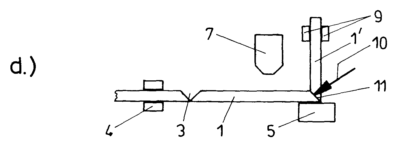
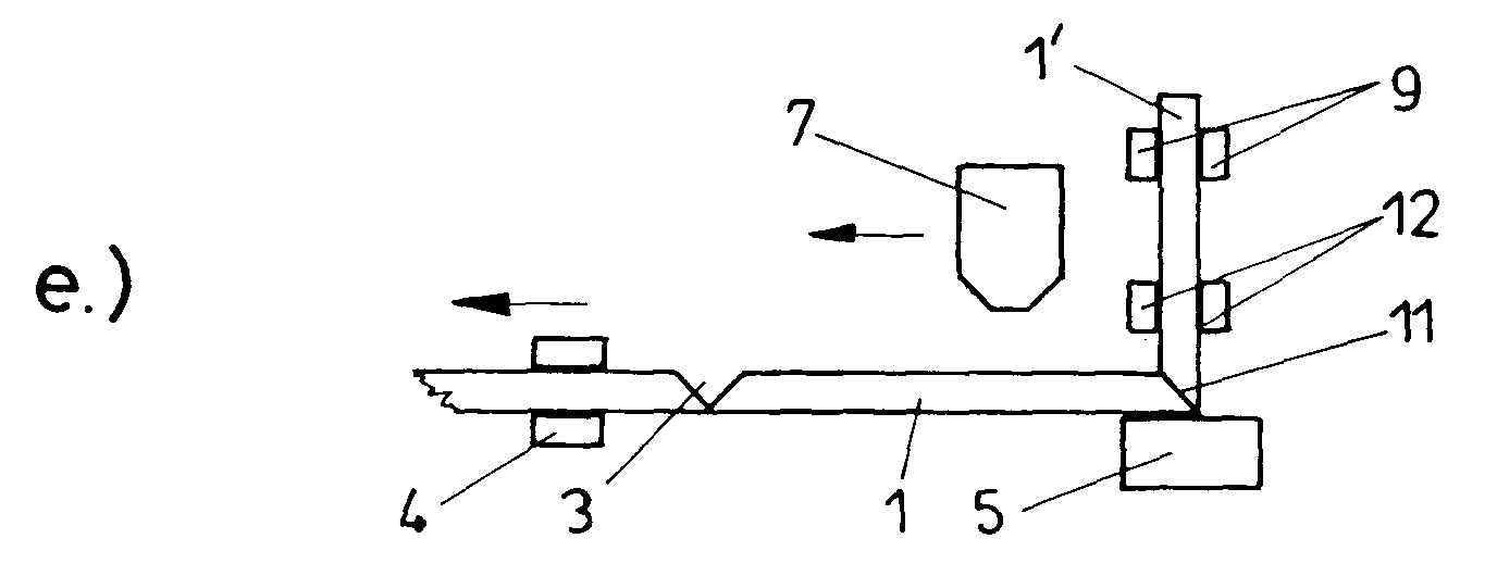
- the section is angled upwards 1 'of the hollow profile strip 1 with a feed device at least one clamp 12 detects and the clamp 9 of the pivot lever solved (Fig. 1e and 1f).
- the hollow profile bar 1 is with the help of the feed device, preferably supported by the feed gripper 4, transported until the corner 11 in the area a curing point, in the case of the use of thermoplastic Plastic, is arranged in a cooling block 13.
- the distance of the Cooling blocks 13 from the bending point 5 can be chosen so that the Corner 11 is included in the cooling block 13 as soon as the next miter cut 3 is arranged in the bending point 5. But it is also possible to move the corner 11 into the cooling block 13 beforehand and then move it along with the hollow profile strip 1, until the next miter cut 3 in the bending point 5 is arranged. This is shown in Fig. 1f. 1f is also shown that the hollow profile bar 1 from the open side of a Miter cut 3 with hot air 8 acting nozzle 7 at Pushing the angled hollow profile bar 1 moves with it can be.
- a modified way of working is when manufacturing a spacer first according to FIGS. 1a to 1f and then as below described with reference to FIGS. 1k to 1n.
- the top part to be pivoted here: sections 1 'and 1 " of the hollow profile strip 1 not only through the jaw of clamp 9 on the swivel lever detected, but also through the already angled leg 1 ' at least one terminal 9 'is detected.
- Terminal 9 ' moves synchronously with the one or more terminals 9 to the hollow profile bar 1 - in the shown Embodiment by 90 ° - to bend.
- This way of working has the advantage that the corner 11 also at and after moving out of the cooling block 13 of the at least one at the section 1 'of the hollow profile strip 1 engaging clamp 9' is supported so that undesirable deformations in the area of the corner 11 are avoided.
- this way of working allows Time period during which a corner 11 to harden the corner 11 injected plastic must remain in the cooling block 13 to shorten, so the cycle time for making a spacer can be further shortened.
- Fig. 1m shows the position of the clamp 9 'with the jaws after Swing up and shows that the swung up from the cooling block 13 Corner 11 (Fig. 1l - Fig. 1m) during the swinging up and after through terminals 9 and 9 ', which are connected to sections 1' and 1 " attack is stabilized.
- the terminals 9 and 9 ' are preferably on a common, pivotable Lever attached, the clamp 9 on the lever in in a direction parallel to the non-curved hollow profile strip 1 is adjustable so that it is opposite the pivoted section 1 'of the hollow profile strip 1 can be aligned before their Clamping jaws as shown in Fig. 1l applied to section 1 ' become.
- the cycle time is particularly short when the one injected into the corner Plastic is already hardened (cooled) while the Hollow profile strip 1 is advanced to the next miter cut 3 into the bending point 5 by the cooling block 13 the bending point 5 is approximated and then moved with the corner 11 becomes. So time can be saved because the hardening of the in the Corner 11 injected mass begins while the hollow section 1 is advanced.
- spacers be produced with legs perpendicular to each other can.
- Spacers made of hollow profile strips can be made in the same way (made of plastic), which lead to at least two corners Leg of the spacer with each other an angle other than 90 ° include, or spacers with fewer or more than four Corners are made.
- the invention shown by way of example in the drawings Device has an obliquely backwards upwards, i.e. of the Operating side inclined, rising support wall 20 on the to Above angled sections 1 ', 1 "of the hollow profile strip 1 rest and under their lower edge 21 in the embodiment shown Bending point 5 is provided.
- the bending point 5 is the hollow profile bar 1 right angle or with any other Angle bent.
- the bending point has 5 jaws 22, 23 and between these a support 24 (Fig. 6) as a support for the Hollow profile strip 1 so that it is held during the bending process is.
- a pivot lever 25 with two in the exemplary embodiment Terminals 9 provided with which the projecting beyond the bending point 5 Section of the hollow profile strip 1 for producing a corner 11 can be pivoted upwards.
- angled supports 31 Opposite the lower edge 21 of the support wall 20 are on the machine frame 30 attached, angled supports 31 provided in which the hollow profile strip 1 to be bent is inserted.
- a (Cut to length) hollow profile strip 1 becomes a standby position on a conveyor track 26 behind the support wall 20 under the lower Edge 21 of the same moved past in the support 31.
- the angled Bearings 31 have a leg with a bearing surface, which in the level of the support wall 20 lies, and a leg with one to Support wall 20 vertical, obliquely upward contact surface (Fig. 3).
- a magazine 32 for hollow profile strips 1 made of metal or plastic which consists of several for Support wall 20 vertically aligned strips 33, 34 which between each a compartment 35 for receiving a stack of hollow profile strips Form 1, exists.
- a transport device on the conveyor track 26 which is behind the retaining wall 20 and over the side of the support wall opposite the magazine 32 20 extends, pushed.
- At the beginning of the conveyor track 26 is one Cross-cut saw 41 for cutting the hollow profile strips 1 to the for Making the desired spacer required length provided.
- a (not shown) device can be provided with the hollow profile strips with straight connector pieces or injected plastic can be connected to longer sections.
- the conveyor track 26 for hollow profile strips 1 is in the embodiment shown from a series of groups 43 of three each Rollers 44, 45, 46 formed, the arms 47 freely rotatably mounted are.
- the arms 47, on each of which a group 43 three rollers 44, 45, 46, whose axes of rotation to the conveying direction (arrow) are aligned vertically, are stored, are in common Beams 49 fixed at a distance from each other.
- the bar 49 is in turn with the help of at least one piston-cylinder unit 50 in Machine frame 30 about an axis 51 parallel to the conveying direction pivotable, so that the groups forming the conveyor track 26 43 of Rollers 44, 45, 46 from the path of movement in which the hollow profile strips 1 are pushed out of the magazine 32 onto the conveyor track 26, can be lowered.
- the groups 43 of rollers 44, 45, 46 thus together form the conveyor track 26 for hollow profile strips 1, which are behind the support wall 20th and towards it, i.e. is open diagonally upwards.
- a relocating device provided with grippers 60.
- Each gripper 60 has two axes aligned parallel to the conveying direction (arrow) swiveling gripper jaws with pads made of elastic material, the from their open position to the closed position, in the they capture a hollow profile strip 1 (Fig. 3 and 4), pivotable are.
- Each gripper 60 is attached to an arm 61.
- the arms are 61 in turn attached to a common beam 62.
- the bar 62 is supported by at least two guide rails 63, which are in the machine frame 30 are movable.
- For moving the guide rails 63 are arms 65 attached to a shaft 64 via push rods 66 coupled with the guide rails 63.
- shaft 64 is at least one pressure medium motor (double-acting, not shown) provided, for example attacks one of the arms 65.
- Each guide rail 63 is over three rollers 67, 68, 69, which in Longitudinal direction of the guide rail 63 offset from one another in the machine frame 30 are stored, guided. It is in the embodiment shown that arranged closer to the beam 62 for the grippers 60 Roller 67 in the machine frame 30 stationary, but freely rotatable stored, whereas the rollers further away from the beam 62 68, 69 in the machine frame 30 are adjustable up and down. So can the grippers 60 at the end of the feed movement when the grippers 60 have moved a hollow profile strip 1 to the supports 31, lowered by lifting rollers 68 and 69. So can the hollow profile bar 1 from the grippers 60 from above into the Bearings 31 are inserted after the gripper 60 the hollow profile bar 1 moved under the lower edge 21 of the support wall 20 to have.
- the bending point 5 adjacent end is still next to this, in the zero position that can be defined by a stop (not shown), and then continue to the starting position, in which the first miter cut 3 in the bending point 5 the correct position for the first turn occupies, and for transporting the hollow profile bar 1 between the Bending processes is a feed device 4 with a gripper 70 provided for parallel movement of a hollow profile strip 1 can be advanced to the conveying direction and again at idle stroke can be moved back.
- A can be used to measure and control the feed Position measuring device, in particular an incremental encoder, with the Drive of the gripper 70 is coupled, may be provided.
- the gripper 70 can, for example, the construction shown in FIG. 5 have.
- a lower jaw 75 of the feed gripper 70 on a carriage 76 which at least one running parallel to the supports 31 (not shown) Guide rail is guided, attached.
- An upper jaw 77 is over Parallelogram link 78 movably supported on the carriage 76.
- To the The jaw 77 is actuated by a double-acting pressure medium motor 79 intended.
- the movable jaw 77 can from the pressure medium motor 79 be moved far away from the lower jaw 75 to carry it away a finished spacer is not hindered.
- a feed device 100 with at least one, preferably two Clamps 12 and a cooling block 13 arranged next to this.
- a device 80 for making miter cuts 3 in hollow profile strips 1 intended In the area of the conveyor track 26 for feeding hollow profile strips 1, which is arranged behind the support wall 20 is a device 80 for making miter cuts 3 in hollow profile strips 1 intended.
- This device 80 for making the miter cuts 3 can work and generate with a router or saw Miter cuts 3, which later up to the outer wall of the Spacer-forming wall of the hollow profile strip 1 are sufficient.
- the Angle of the miter cuts 3 is made according to the desired Angle that the leg of the spacer leading to a corner should include each other. Instead of a router can also be adjusted and fixed in appropriate angular positions Saws for making the miter cuts 3 may be provided.
- a practical embodiment of one for performing on hand 1a to f and k to n shown variant of the invention 2a shows a device suitable for the method. It is can be seen that not only at least one on the pivot lever 25 Terminal 9 with two jaws, but at a shoulder 25 'of Swivel lever 25 at least one further clamp 9 'with two jaws is arranged.
- the approach 25 'carrying the clamp 9' is in Longitudinal direction of the pivot lever 25 adjustable so that the clamp 9 ' in for the detection of a pivoted section 1 'or 1 "of the hollow profile bar 1 correct position can be moved.
- the cooling block 13 is horizontal is displaceable so that one by bending the hollow profile bar 1 generated corner 11 immediately after it came out of the bending point 5 has been moved out into the cooling block 13 and then is advanced together with this when the next miter cut 3 is aligned in the bending point 5.
- the bending point 5 has in Fig. 6 in more detail Embodiment shown jaws 22 and 23 at a distance from each other according to the width of the hollow profile strip to be machined 1 can be set.
- a cheek preferably the support wall-side jaw 22, stationary in the machine frame 30 mounted, while the other jaw 23 with the help of one not closer shown drive, guided on rod-shaped guides 27 and 28, is adjustable.
- the support 24 is to be bent Hollow profile strip 1 is provided. Also the two rod-shaped guides 27 can serve as a support for the hollow profile strip 1.
- a nozzle 7 which is supplied with hot air 8, which are provided from above, hot air 8 into the miter cut from the open side 3 blows.
- This nozzle 7 is arranged behind the support wall 20 and can by adjusting in the direction of the double arrow 82 of the hollow profile bar 1 can be approximated.
- the nozzle is 7 in Direction of the double arrow 83 adjustable, on the one hand to later to remove them from their active position and on the other hand so that they Transporting a hollow profile strip 1 with a miter cut 3 can be moved when a hollow profile bar 1 is already during the transport in the area of a miter cut 3 heated shall be.
- An injection device 90 is displaceable in the machine frame 30 arranged with a conical tip 91 (injector), the on a guide rail 92 using a carriage and a Pressure cylinder not shown in the direction of the double arrow 93 can be adjusted.
- injector When injecting plastic into the area of a corner 11 produced in the hollow profile strip 1 the injector 91 through an opening 94 in the fixed Jaw 22 advanced until it is in the area of the bent Hollow profile strip 1 abutting edges of the miter cut 3 protrudes into the interior of the hollow profile strip 1.
- the injection cylinder for plastic of the injection device 90 is assigned a metering device, which the required Amount of plastic - in the case of thermoplastic - in the form of Granules - in the injection cylinder, from which the plastic feeds by actuating the injection cylinder in the corner of the hollow profile bar 1 can be injected.
- thermoplastic Heating up plastic is one of the injection cylinders preferably associated with electrical, heating.
- the conical injection nozzle 91 is (FIG. 6a) with an underneath provide the shut-off valve that automatically opens the injection pressure, so that the post-flow of plastic once the injection pressure is undershot, is prevented.
- An example embodiment this valve is shown in Fig. 6a. It can be seen that the ball 96 under the action of the closing spring loading it 97 prevents the escape of plastic from the mouth of the nozzle 91.
- the injection pressure is chosen so high that the ball 96th is pushed back against the action of its closing spring 97 and the, for example, annular outlet opening of the feed channel releases.
- the pivot lever 25 For pivoting the section projecting beyond the bending point 5 the hollow profile bar 5, the pivot lever 25 is provided on preferably two clamps 9 (FIG. 2), each with two clamping jaws are attached. If a section projecting beyond the bending point 5 the hollow profile strip 1 is to be pivoted for bending, the jaws of the clamps 9 on the projecting section and if there is an already angled section (see Fig. 1l and m) also the terminal 9 'applied to this and then the Swivel lever 25 pivoted through the desired angle - usually 90 °.
- the pivot lever 25 is connected to a crank drive 95.
- the crank of the crank drive 95 for pivoting the pivot lever 25 is coupled to the pivot lever 25 via a push rod.
- the Drive motor for adjusting the pivot lever 25 is preferred a stepper motor so that the desired swivel angle is reached can be.
- the clamps 9 on the swivel lever 25 and the clamp 9 'on the shoulder 25' are arranged so that their jaws in the shown in Fig. 6 Stand by position next to the hollow profile bar 1, so that the further transport of an at least once angled hollow profile strip 1 do not hinder.
- the feed device shown in greater detail in FIGS. 7 and 8 100 is slidably guided in the machine frame 30 and has a carrier 101, on which the terminals 12, each with two jaws are attached.
- the drive for moving the feed device 100 can be of any design.
- the feed device 100 is - after the Hot air nozzle 7 has been moved away from the bending point 5 - for Bending point 5 adjusted and detected depending on the length of the swung up Section 1 ', 1 "of the hollow profile strip 1 this swung up Section 1 ', 1 "with one or with both clamps 12, even before the terminals 9 of the pivot lever 25 and, if necessary the clamps 9 'detached from the pivoted section 1', 1 " to have.
- the position of the swung-up section 1 ', 1 " fixed, even after the terminals 9 and 9 'detached from it to have.
- the hollow profile bar 1 advanced until the next miter cut 3 is aligned in the bending point 5. Because the swung up Section through the clamps 12 of the feed device 100 is stabilized, the advancement takes place without changing the angle, the sections of the hollow profile strip 1 leading to the corner 11 include with each other.
- the support wall 20 can be replaced by an in advance their intended slot and behind the support wall 20 retractable (arrow 132) support ledge 130 with forward-pointing for example, sawtooth-like recesses 131 may be provided.
- the support bar 131 is behind the support wall 20 withdrawn.
- the cooling block 13 is horizontal on one in the machine frame 30 by a drive movable cylinder 112 up and adjustable so that it is applied to a corner 11 or previously can be positioned.
- the cooling block 13 has one Recess 110, in which a corner 11 is received.
- cold air 14 is blown into the cooling block 13 via a line 111, so that the plastic injected into the corner 11 quickly cools and hardens.
- a groove 114 is provided in the recess 110 in the cooling block 13, the exit of cooling air in the corner region of the recess 110 of the Cooling blocks 13 supported and designed the cooling effectively.
- the Cooling block 13 lowered by actuating the pressure medium cylinder 112, after the terminals 9 (and possibly 9 ') on the pivot lever 25 the section lying between the bending point 5 and the cooling block 13 1 ', 1 "of the hollow profile strip 1.
- the Clamps 12 of the feed device 100 from the angled section the hollow profile bar 1 solved and a new pivoting process to Bend the hollow profile strip 1 to produce the next corner 11 can be executed.
- cooling block 13 is horizontally adjustable, so can be worked that the cooling block 13 of the bending point 5 approximated while the feed device 100 is in the bending point 5 is aligned. If the hollow profile strip 1 is then advanced the next miter cut 3 in the bending point 5 to align, the cooling block 13 with the hollow profile bar 1 moves, the corner 11 in the recess 110 of the cooling block 13th is recorded. This already allows the cooling process to begin while advancing the hollow profile bar 1.
- the carrier 101 of the feed device 100 is on which the terminals 12 are mounted, arranged behind the support wall 20. So that the upper terminal 12 of the feed device 100 for the stabilized advancement of the hollow profile strip 1, i.e. a pushing forward without changing the angle to the corner just created Include the leading leg together, the bent section the hollow profile strip 1 to one of the corner 11 further away Can detect point is a horizontal in the support wall 20 Slot 120 provided.
- a hollow profile strip 1 becomes a spacer for insulating glass manufactured by making miter cuts 3 in the hollow profile strip 1 are produced, which are provided with miter cuts 3
- Hollow profile strip 1 is angled several times and in the area of everyone of the corners 11 thus produced is the angular position of the corners leading leg defining, hardening mass is injected. Every time after injected into a corner 11 hardening mass has been, the hollow profile bar 1 while maintaining the angle, the sections of the hollow profile strip leading to corner 11 1 enclose with each other, transported from the bending point 5, around the next miter cut 3 into the bending point 5 move before the hardening injected into the corner 11 Mass is hardened.
Landscapes
- Engineering & Computer Science (AREA)
- Civil Engineering (AREA)
- Structural Engineering (AREA)
- Shaping Of Tube Ends By Bending Or Straightening (AREA)
- Securing Of Glass Panes Or The Like (AREA)
Abstract
Description
Claims (37)
- Verfahren zum Herstellen von Abstandhaltern für Isolierglas aus Hohlprofilleisten, bei dem in der Hohlprofilleiste Gehrungseinschnitte hergestellt werden, bei dem die mit Gehrungseinschnitten versehene Hohlprofilleiste zum Ausbilden von Ecken abgewinkelt wird und bei dem in den Bereich der Ecken eine erhärtende Masse eingebracht wird, dadurch gekennzeichnet, daß die Hohlprofilleiste jeweils nach dem Herstellen einer Ecke und nachdem erhärtende Masse in eine Ecke eingebracht worden ist, unter Beibehalten des Winkels, den die zur Ecke führenden Abschnitte der Hohlprofilleiste miteinander einschließen, aus der Biegestelle wegbewegt wird, um den nächsten Gehrungseinschnitt in die Biegestelle zu bewegen, noch bevor die in den Bereich der Ecke eingespritzte, erhärtende Masse erhärtet ist.
- Verfahren nach Anspruch 1, dadurch gekennzeichnet, daß in die Ecke erhitzter, thermoplastischer Kunststoff eingespritzt wird.
- Verfahren nach Anspruch 2, dadurch gekennzeichnet, daß der thermoplastische Kunststoff zum Erhärten zwangsgekühlt wird.
- Verfahren nach Anspruch 3, dadurch gekennzeichnet, daß zwangsgekühlt wird, wenn der nächste Gehrungseinschnitt in der Hohlprofilleiste in der Biegestelle angeordnet ist.
- Verfahren nach Anspruch 3 oder 4, dadurch gekennzeichnet, daß mit dem Zwangskühlen des thermoplastischen Kunststoffes begonnen wird, während die Hohlprofilleiste weiterbewegt wird, um den nächsten Gehrungseinschnitt in die Biegestelle zu bewegen.
- Verfahren nach Anspruch 1, dadurch gekennzeichnet, daß in die Ecke eine durch chemische Reaktion, gegebenenfaflls unterstützt durch Energiezufuhr, aushärtende Masse eingespritzt wird.
- Verfahren nach Anspruch 63, dadurch gekennzeichnet, daß das Aushärten der in die Ecke eingespritzten Masse durch chemische Reaktion und/oder durch Energiezufuhr bewirkt oder beschleunigt wird.
- Verfahren nach Anspruch 7, dadurch gekennzeichnet, daß die in die Ecke eingespritzte Masse gehärtet wird, wenn der nächste Gehrungseinschnitt in der Hohlprofilleiste in der Biegestelle angeordnet ist.
- Verfahren nach Anspruch 3, 7 oder 8, dadurch gekennzeichnet, daß mit dem Aushärten der Masse begonnen wird, während die Hohlprofilleiste weiterbewegt wird, um den nächsten Gehrungseinschnitt in die Biegestelle zu bewegen.
- Verfahren nach einem der Ansprüche 3 und 7 bis 9, dadurch gekennzeichnet, daß in die Ecke eingespritzter Kunststoff durch chemische Reaktion und/oder durch Energiezufuhr gehärtet wird.
- Verfahren nach einem der Ansprüche 1 bis 10, dadurch gekennzeichnet, daß eine Hohlprofilleiste aus thermoplastischem Kunststoff im Bereich eines Gehrungseinschnittes erwärmt wird, bevor sie im Bereich des Gehrungseinschnittes abgewinkelt wird.
- Verfahren nach Anspruch 11, dadurch gekennzeichnet, daß die Hohlprofilleiste aus Kunststoff erwärmt wird, wenn der Gehrungseinschnitt in der Biegestelle angeordnet ist.
- Verfahren nach Anspruch 11 oder 12, dadurch gekennzeichnet, daß die Hohlprofilleiste im Bereich des Gehrungseinschnittes erwärmt wird, während er zur Biegestelle bewegt wird.
- Verfahren nach einemn der Ansprüche 11 bis 13, dadurch gekennzeichnet, daß die Hohlprofilleiste im Bereich eines Gehrungseinschnittes durch Beblasen mit Heißluft erwärmt wird.
- Verfahren nach Anspruch 14, dadurch gekennzeichnet, daß Heißluft auf die durchgehende, im Abstandhalter die Außenwand bildende Wand der Hohlprofilleiste geblasen wird.
- Verfahren nach Anspruch 14 oder 15, dadurch gekennzeichnet, daß Heißluft in die offenen Seite des Gehrungseinschnittes gerichtet wird.
- Verfahren nach Anspruch 16, dadurch gekennzeichnet, daß Heißluft in die offene Seite des Gehrungseinschnittes geblasen wird, während die Hohlprofiflleiste bewegt wird, um einen Gehrungseinschnitt in die Biegestelle zu bewegen.
- Verfahren nach einem der Ansprüche 1 bis 17, dadurch gekennzeichnet, daß erhärtende Masse in die Hohlprofilleiste zwischen bei abgewinkelter Hohlprofilleiste aneinander anliegenden Rändern des Gehrungseinschnittes gespritzt wird.
- Verfahren nach einem der Ansprüche 1 bis 18, dadurch gekennzeichnet, daß der Winkel, den die zur Ecke führenden Abschnitte der Hohlprofilleiste miteinander einschließen, während des Abwinkelns der Hohlprofilleiste zum Herstellen der nächsten Ecke stabilisiert wird.
- Verfahren nach Anspruch 19, dadurch gekennzeichnet, daß die Ecke stabilisiert wird, indem beide zu einer Ecke führenden Abschnitte der Hohlprofilleiste während des Abwinkelns der Hohlprofilleiste zum Ausbilden der nächsten Ecke gehalten werden.
- Vorrichtung zum Ausführen des Verfahrens nach einem oder mehreren der Ansprüche 1 bis 20, mit einer Stützwand (20), mit einer Zuführvorrichtung (4) für eine mit Gehrungseinschnitten (3) versehene Hohlprofilleiste (1), mit einer Biegestelle (5) und mit einer Einrichtung (10, 90) zum Einbringen erhärtender Masse in den Bereich einer hergestellten Ecke (11), dadurch gekennzeichnet, daß der Biegestelle (5) ein Schwenkhebel (25) mit wenigstens einer an die Hohlprofilleiste (1) anlegbaren Klemme (9) zugeordnet ist, daß eine Vorschubvorrichtung (100) mit wenigstens einer an einem nach oben abgewinkelten Abschnitt (1', 1") der Hohlprofilleiste (1) anlegbaren Klemme (12) vorgesehen ist, und daß eine Einrichtung (13) vorgesehen ist, in welcher der in eine Ecke (11) eingespritzte Kunststoff aushärtet.
- Vorrichtung nach Anspruch 21, dadurch gekennzeichnet, daß die Biegestelle (5) zwei Backen (22, 23), die an den Seitenwangen der Hohlprofilleiste (1) anlegbar sind, und eine Abstützung (24), auf der die Unterseite der Hohlprofilleiste (1) aufliegt, aufweist.
- Vorrichtung nach Anspruch 22, dadurch gekennzeichnet, daß in der Auflage (24) für die Hohlprofilleiste (1) in der Biegestelle (5) eine Düse (81) für das Zuführen von Heißluft (6) vorgesehen ist.
- Vorrichtung nach Anspruch 22 oder 23, dadurch gekennzeichnet, daß die Einspritzdüse (91) der Einrichtung (10, 90) zum Einspritzen von Kunststoff in den Bereich einer Ecke (11) durch eine Öffnung (94) in der einen Backe (22) bis in den Innenraum der Hohlprofilleiste (1) ragend vorschiebbar ist.
- Vorrichtung nach einem der Ansprüche 21 bis 24, dadurch gekennzeichnet, daß eine Düse (7) vorgesehen ist, die an eine Quelle für Heißluft (8) angeschlossen ist, und daß die Düse (7) im Maschinengestell (30) horizontal verfahrbar angeordnet ist.
- Vorrichtung nach einem der Ansprüche 21 bis 25, dadurch gekennzeichnet, daß die Vorschubvorrichtung (100) mit der wenigstens einen Klemme (12) zum Erfassen eines von der Biegestelle (5) nach oben ragenden Abschnittes der Hohlprofilleiste (1) aus einer Bereitschaftsstellung, in der die Vorschubvorrichtung (100) neben der Biegestelle (5) angeordnet ist, in eine in der Biegestelle (5) ausgerichtete Lage verfahrbar ist.
- Vorrichtung nach einem der Ansprüche 21 bis 26, dadurch gekennzeichnet, daß die Vorrichtung zum Härten von in eine Ecke (11) eingespritztem, thermoplastischem Kunststoff ein Kühlblock (13) ist.
- Vorrichtung nach Anspruch 27, dadurch gekennzeichnet, daß der Kühlblock (13) eine Aussparung (110) für die Ecke (11) aufweist.
- Vorrichtung nach Anspruch 27 oder 28, dadurch gekennzeichnet, daß der Kühlblock (13) an einem Träger (101) im Maschinengestell (30) horizontal verfahrbar angeordnet ist.
- Vorrichtung nach Anspruch 29, dadurch gekennzeichnet, daß der Träger (101) ein Druckmittelmotor ist, mit dem der Kühlblock (13) im Maschinengestell (30) auf- und abverstellbar ist.
- Vorrichtung nach einem der Ansprüche 21 bis 30, dadurch gekennzeichnet, daß die wenigstens eine Klemme (9) des Schwenkhebels (25) und die wenigstens eine Klemme (12) der Vorschubvorrichtung (100) an einem zum Ausbilden einer Ecke (11) verschwenkten Abschnitt (1', 1") der Hohlprofilleiste (1) gleichzeitig anlegbar sind.
- Vorrichtung nach einem der Ansprüche 21 bis 31, dadurch gekennzeichnet, daß die Vorschubvorrichtung (100), insbesondere ihr Träger (101), hinter der Stützwand (20) angeordnet ist und daß die Backen der wenigstens einen Klemme (12) der Vorschubvorrichtung (100) in ihrer Wirkstellung bis auf die Vorderseite der Stützwand (20) ragen.
- Vorrichtung nach Anspruch 30 oder 31, dadurch gekennzeichnet, daß der Träger (101) für den Kühlblock (13) hinter der Stützwand (20) angeordnet ist und daß der Kühlblock (13) unter dem unteren Rand (21) der Stützwand (20) und vor dieser angeordnet ist.
- Vorrichtung nach einem der Ansprüche 21 bis 33, dadurch gekennzeichnet, daß der Schwenkhebel (25) zusätzlich zu der wenigstens einen an der Hohlprofilleiste (1) anlegbaren Klemme (9) wenigstens eine zusätzliche Klemme (9') aufweist, die an einem bereits abgewinkelten Abschnitt (1', 1") der Hohlprofilleiste (1) anlegbar ist.
- Vorrichtung nach Anspruch 34, dadurch gekennzeichnet, daß der Abstand der wenigstens einen weiteren Klemme (9') vom Schwenkhebel (25) verstellbar ist.
- Vorrichtung nach Anspruch 34 oder 35, dadurch gekennzeichnet, daß die wenigstens eine weitere Klemme (9') an dem Schwenkhebel (25) in dessen Längsrichtung verstellbar ist.
- Vorrichtung nach einem der Ansprüche 21 bis 36, dadurch gekennzeichnet, daß die am Schwenkhebel (25) vorgesehenen Klemmen (9 und 9') vor der Vorderseite der Stützwand (20) angeordnet sind.
Applications Claiming Priority (2)
| Application Number | Priority Date | Filing Date | Title |
|---|---|---|---|
| AT24899A AT406889B (de) | 1999-02-16 | 1999-02-16 | Verfahren und vorrichtung zum herstellen von abstandhalterrahmen für isolierglasscheiben aus hohlprofilleisten |
| AT24899 | 1999-02-16 |
Publications (2)
| Publication Number | Publication Date |
|---|---|
| EP1030024A2 true EP1030024A2 (de) | 2000-08-23 |
| EP1030024A3 EP1030024A3 (de) | 2001-05-02 |
Family
ID=3485499
Family Applications (1)
| Application Number | Title | Priority Date | Filing Date |
|---|---|---|---|
| EP00890040A Withdrawn EP1030024A3 (de) | 1999-02-16 | 2000-02-15 | Verfahren und Vorrichtung zum Herstellen von Abstandhaltern für Isolierglas aus Hohlprofilleisten |
Country Status (2)
| Country | Link |
|---|---|
| EP (1) | EP1030024A3 (de) |
| AT (1) | AT406889B (de) |
Cited By (11)
| Publication number | Priority date | Publication date | Assignee | Title |
|---|---|---|---|---|
| EP1233136A1 (de) * | 2001-02-17 | 2002-08-21 | Wilfried Ensinger | Kunststoff-Abstandshalterrahmen und Verfahren zu seiner Herstellung |
| DE102004027527A1 (de) * | 2004-02-03 | 2005-08-18 | Karl Lenhardt | Verfahren zum Herstellen einer Isolierglasscheibe |
| DE102005037303A1 (de) * | 2005-01-18 | 2006-07-27 | Karl Lenhardt | Abstandhalter für Isolierglasscheiben und Verfahren zu seiner Herstellung |
| DE102008044771B3 (de) * | 2008-08-28 | 2009-11-26 | R & R Sondermaschinen Gmbh | Verfahren und Vorrichtung zum Herstellen eines rechteckigen Abstandhalterrahmens für Isolierglasscheiben |
| DE102009017705A1 (de) | 2008-04-11 | 2010-02-04 | Plus Inventia Ag | Verfahren zum Herstellen einer Ecke eines rahmenförmigen Abstandhalters für Isolierglasscheiben und nach dem Verfahren hergestellte Abstandhalter und Isolierglasscheiben |
| WO2010001222A3 (en) * | 2008-07-02 | 2010-07-22 | Saint-Gobain Performance Plastics Chaineux | Framed device, seal, and method for manufacturing same |
| CN102712062A (zh) * | 2009-11-11 | 2012-10-03 | 通快机床两合公司 | 用于制造一体式角接的方法 |
| AT512718A1 (de) * | 2012-03-19 | 2013-10-15 | Fux Maschb U Kunststofftechnik Gmbh | Verfahren und Vorrichtung zum Biegen einer Ecke in ein Profil aus thermoplastischem Grundmaterial |
| US8769889B2 (en) | 2008-02-19 | 2014-07-08 | Plus Inventia Ag | Spacer for insulating glass panes |
| CN106040906A (zh) * | 2015-04-02 | 2016-10-26 | 伦巴达机械有限公司来自G.B.拉图阿达公司 | 将适于绝缘玻璃板-双层玻璃的间隔元件自动折弯的方法以及执行该方法的机器 |
| AT519975B1 (de) * | 2018-03-20 | 2018-12-15 | Lisec Austria Gmbh | Verfahren und Werkzeug zum Erzeugen eines Eindruckes |
Families Citing this family (1)
| Publication number | Priority date | Publication date | Assignee | Title |
|---|---|---|---|---|
| DE102023111811A1 (de) * | 2023-05-05 | 2024-11-07 | Baosteel Lasertechnik Gmbh | Laservorrichtung und Verfahren, insbesondere zur Herstellung eines ringförmig, geschlossenen Bauteils |
Family Cites Families (4)
| Publication number | Priority date | Publication date | Assignee | Title |
|---|---|---|---|---|
| DE2905841C2 (de) * | 1979-02-15 | 1984-04-19 | Josef Käuferle KG Stahlbau, 8890 Aichach | Verfahren und Anlage zur Herstellung einer Verbundplatte |
| AT401627B (de) * | 1987-03-09 | 1996-10-25 | Lisec Peter | Vorrichtung zum herstellen von abstandhalterrahmen für isolierglasscheiben |
| GB2237051A (en) * | 1989-10-21 | 1991-04-24 | Gary Daynes | Square cornered spacer tube & method of making it |
| DE4401667C2 (de) * | 1993-02-26 | 1996-05-02 | Ladislaus Galac | Abstandshalterrahmen für eine Isolierscheibe und Vorrichtung zu seiner Herstellung |
-
1999
- 1999-02-16 AT AT24899A patent/AT406889B/de not_active IP Right Cessation
-
2000
- 2000-02-15 EP EP00890040A patent/EP1030024A3/de not_active Withdrawn
Cited By (16)
| Publication number | Priority date | Publication date | Assignee | Title |
|---|---|---|---|---|
| EP1233136A1 (de) * | 2001-02-17 | 2002-08-21 | Wilfried Ensinger | Kunststoff-Abstandshalterrahmen und Verfahren zu seiner Herstellung |
| DE102004027527A1 (de) * | 2004-02-03 | 2005-08-18 | Karl Lenhardt | Verfahren zum Herstellen einer Isolierglasscheibe |
| DE102005037303A1 (de) * | 2005-01-18 | 2006-07-27 | Karl Lenhardt | Abstandhalter für Isolierglasscheiben und Verfahren zu seiner Herstellung |
| US8769889B2 (en) | 2008-02-19 | 2014-07-08 | Plus Inventia Ag | Spacer for insulating glass panes |
| US8615883B2 (en) | 2008-04-11 | 2013-12-31 | Plus Inventia Ag | Method for producing a corner of a frame-shaped spacer for insulating glass panes and spacer and insulating glass panes produced according the method |
| DE102009017705A1 (de) | 2008-04-11 | 2010-02-04 | Plus Inventia Ag | Verfahren zum Herstellen einer Ecke eines rahmenförmigen Abstandhalters für Isolierglasscheiben und nach dem Verfahren hergestellte Abstandhalter und Isolierglasscheiben |
| WO2010001222A3 (en) * | 2008-07-02 | 2010-07-22 | Saint-Gobain Performance Plastics Chaineux | Framed device, seal, and method for manufacturing same |
| DE102008044771B3 (de) * | 2008-08-28 | 2009-11-26 | R & R Sondermaschinen Gmbh | Verfahren und Vorrichtung zum Herstellen eines rechteckigen Abstandhalterrahmens für Isolierglasscheiben |
| EP2159366A2 (de) | 2008-08-28 | 2010-03-03 | R & R Sondermaschinen GmbH | Verfahren und Vorrichtung zum Herstellen eines rechteckigen Abstandhalterrahmens für Isolierglasscheiben |
| CN102712062B (zh) * | 2009-11-11 | 2015-09-16 | 通快机床两合公司 | 用于制造一体式角接的方法 |
| CN102712062A (zh) * | 2009-11-11 | 2012-10-03 | 通快机床两合公司 | 用于制造一体式角接的方法 |
| AT512718B1 (de) * | 2012-03-19 | 2013-12-15 | Fux Maschb U Kunststofftechnik Gmbh | Verfahren und Vorrichtung zum Biegen einer Ecke in ein Profil aus thermoplastischem Grundmaterial |
| AT512718A1 (de) * | 2012-03-19 | 2013-10-15 | Fux Maschb U Kunststofftechnik Gmbh | Verfahren und Vorrichtung zum Biegen einer Ecke in ein Profil aus thermoplastischem Grundmaterial |
| CN106040906A (zh) * | 2015-04-02 | 2016-10-26 | 伦巴达机械有限公司来自G.B.拉图阿达公司 | 将适于绝缘玻璃板-双层玻璃的间隔元件自动折弯的方法以及执行该方法的机器 |
| AT519975B1 (de) * | 2018-03-20 | 2018-12-15 | Lisec Austria Gmbh | Verfahren und Werkzeug zum Erzeugen eines Eindruckes |
| AT519975A4 (de) * | 2018-03-20 | 2018-12-15 | Lisec Austria Gmbh | Verfahren und Werkzeug zum Erzeugen eines Eindruckes |
Also Published As
| Publication number | Publication date |
|---|---|
| EP1030024A3 (de) | 2001-05-02 |
| ATA24899A (de) | 2000-02-15 |
| AT406889B (de) | 2000-10-25 |
Similar Documents
| Publication | Publication Date | Title |
|---|---|---|
| EP0456121B1 (de) | Verfahren zum Biegen von plattenförmigen Werkstücken sowie Biegemaschine zur Durchführung des Verfahrens | |
| AT406889B (de) | Verfahren und vorrichtung zum herstellen von abstandhalterrahmen für isolierglasscheiben aus hohlprofilleisten | |
| EP0461100B1 (de) | Verfahren und Vorrichtung zum Biegen von Hohlprofilleisten zu Abstandhalterrahmen für Isolierglasscheiben | |
| DE2128717C3 (de) | Verfahren zum Aufbringen eines metallischen Abstandhalters auf die Scheibenränder einer der rechteckigen Glasplatten einer Isolierverglasung und Vorrichtung zur Durchführung des Verfahrens | |
| EP0579593B1 (de) | Vorrichtung zum Herstellen von Abstandhalterrahmen für Isolierglasscheiben aus Hohlprofilleisten | |
| DE1558352B1 (de) | Vorrichtung zum Einstelleneines Schneidwerkzeuges beim Unterteilen von metallischen Straengen,insbesondere Gussstraengen | |
| DE1931905U (de) | Vorrichtung zum herstellen von heizkoerpern in tafel- bzw. plattenform. | |
| DE19828589A1 (de) | Verfahren und Vorrichtung zum Führen des Sägebandes einer Bandsägemaschine | |
| DE69008120T2 (de) | Vorrichtung zur stufenweisen Positionierung, Bearbeitung und Nachbehandlung von Ecken von aus Kunststoff hergestellten Fenster- oder Türrahmen in einer seitlich angeordneten Arbeitsstelle. | |
| DE4116769A1 (de) | Saegeeinrichtung, insbesondere doppelgehrungssaege | |
| EP0459971B1 (de) | Verfahren und Vorrichtung zum Erzeugen gekrümmter Abschnitte in Hohlprofilleisten | |
| DE2013554A1 (de) | Verfahren zum Walzen von Präzisionswerkstücken und Anlage zum Durchführen des Verfahrens | |
| DE29618048U1 (de) | Vorrichtung zum Biegen oder Krümmen von Hohlprofilleisten | |
| DE69129077T2 (de) | Verfahren und vorrichtung zum schneiden von rohren, in welchem die rohre mittels einer rotierenden festhaltplatte in schneidposition gebracht werden | |
| DE19503433C3 (de) | Vorrichtung und Verfahren zum Zuschneiden plattenförmiger Stränge | |
| EP1853785B1 (de) | Verfahren zur Herstellung von Abstandhaltern für Isolierglasscheiben | |
| DE9207639U1 (de) | Vorrichtung zur Herstellung von Rahmen | |
| EP1764177B1 (de) | Ablängvorrichtung für Glasleisten oder entsprechende Stabprofile und Verfahren zum Ablängen von Glasleisten oder entsprechenden Stabprofilen | |
| DE9103838U1 (de) | Schweißvorrichtung für rechteckige Rahmen, insbesondere Fensterrahmen | |
| DE4314707C1 (de) | Verfahren und Vorrichtung zum Aufbringen harten Werkstoffs auf Zähne von Schneidwerkzeugen, insbesondere Sägeblättern | |
| AT401242B (de) | Vorrichtung zum herstellen von abstandhalterrahmen für isolierglasscheiben aus hohlprofilleisten | |
| DE3903513C2 (de) | Vorrichtung zum Sägen von plattenförmigem Sägegut | |
| AT401243B (de) | Vorrichtung zum herstellen von abstandhalterrahmen für isolierglasscheiben aus hohlprofilleisten | |
| DE1629383C3 (de) | Vorrichtung zum Pressen und Erwärmen eines Bandes, insbesondere eines Treibriemens oder Fördergurtes | |
| DE2430420A1 (de) | Verfahren und anlage zur herstellung eines isolierglases |
Legal Events
| Date | Code | Title | Description |
|---|---|---|---|
| PUAI | Public reference made under article 153(3) epc to a published international application that has entered the european phase |
Free format text: ORIGINAL CODE: 0009012 |
|
| AK | Designated contracting states |
Kind code of ref document: A2 Designated state(s): AT CH DE FR LI |
|
| AX | Request for extension of the european patent |
Free format text: AL;LT;LV;MK;RO;SI |
|
| PUAL | Search report despatched |
Free format text: ORIGINAL CODE: 0009013 |
|
| AK | Designated contracting states |
Kind code of ref document: A3 Designated state(s): AT BE CH CY DE DK ES FI FR GB GR IE IT LI LU MC NL PT SE |
|
| AX | Request for extension of the european patent |
Free format text: AL;LT;LV;MK;RO;SI |
|
| RIC1 | Information provided on ipc code assigned before grant |
Free format text: 7E 06B 3/663 A, 7E 06B 3/673 B |
|
| 17P | Request for examination filed |
Effective date: 20010516 |
|
| AKX | Designation fees paid |
Free format text: AT CH DE FR LI |
|
| STAA | Information on the status of an ep patent application or granted ep patent |
Free format text: STATUS: THE APPLICATION IS DEEMED TO BE WITHDRAWN |
|
| 18D | Application deemed to be withdrawn |
Effective date: 20020902 |