EP1030586B1 - Procede et mecanisme d'essorage pour balai a franges - Google Patents
Procede et mecanisme d'essorage pour balai a franges Download PDFInfo
- Publication number
- EP1030586B1 EP1030586B1 EP98966236A EP98966236A EP1030586B1 EP 1030586 B1 EP1030586 B1 EP 1030586B1 EP 98966236 A EP98966236 A EP 98966236A EP 98966236 A EP98966236 A EP 98966236A EP 1030586 B1 EP1030586 B1 EP 1030586B1
- Authority
- EP
- European Patent Office
- Prior art keywords
- stick
- mop
- upper handle
- wringing
- handle
- Prior art date
- Legal status (The legal status is an assumption and is not a legal conclusion. Google has not performed a legal analysis and makes no representation as to the accuracy of the status listed.)
- Expired - Lifetime
Links
- 238000000034 method Methods 0.000 title claims description 32
- 230000007246 mechanism Effects 0.000 title claims description 25
- 239000004744 fabric Substances 0.000 claims description 74
- 238000006243 chemical reaction Methods 0.000 claims description 44
- 230000005484 gravity Effects 0.000 claims description 4
- 230000008901 benefit Effects 0.000 description 6
- 238000005096 rolling process Methods 0.000 description 6
- 241001589086 Bellapiscis medius Species 0.000 description 5
- XLYOFNOQVPJJNP-UHFFFAOYSA-N water Substances O XLYOFNOQVPJJNP-UHFFFAOYSA-N 0.000 description 5
- 238000004140 cleaning Methods 0.000 description 3
- 230000006835 compression Effects 0.000 description 3
- 238000007906 compression Methods 0.000 description 3
- 230000000694 effects Effects 0.000 description 3
- 239000007788 liquid Substances 0.000 description 3
- 239000000463 material Substances 0.000 description 3
- XEEYBQQBJWHFJM-UHFFFAOYSA-N Iron Chemical compound [Fe] XEEYBQQBJWHFJM-UHFFFAOYSA-N 0.000 description 2
- 230000008569 process Effects 0.000 description 2
- 239000008237 rinsing water Substances 0.000 description 2
- 230000002745 absorbent Effects 0.000 description 1
- 239000002250 absorbent Substances 0.000 description 1
- 230000004075 alteration Effects 0.000 description 1
- 229910052782 aluminium Inorganic materials 0.000 description 1
- XAGFODPZIPBFFR-UHFFFAOYSA-N aluminium Chemical compound [Al] XAGFODPZIPBFFR-UHFFFAOYSA-N 0.000 description 1
- 230000006872 improvement Effects 0.000 description 1
- 229910052742 iron Inorganic materials 0.000 description 1
- 238000004519 manufacturing process Methods 0.000 description 1
- 229910052751 metal Inorganic materials 0.000 description 1
- 239000002184 metal Substances 0.000 description 1
- 238000012986 modification Methods 0.000 description 1
- 230000004048 modification Effects 0.000 description 1
- 230000001737 promoting effect Effects 0.000 description 1
- 230000009467 reduction Effects 0.000 description 1
- 238000006467 substitution reaction Methods 0.000 description 1
Images


Classifications
-
- A—HUMAN NECESSITIES
- A47—FURNITURE; DOMESTIC ARTICLES OR APPLIANCES; COFFEE MILLS; SPICE MILLS; SUCTION CLEANERS IN GENERAL
- A47L—DOMESTIC WASHING OR CLEANING; SUCTION CLEANERS IN GENERAL
- A47L13/00—Implements for cleaning floors, carpets, furniture, walls, or wall coverings
- A47L13/10—Scrubbing; Scouring; Cleaning; Polishing
- A47L13/14—Scrubbing; Scouring; Cleaning; Polishing combined with squeezing or wringing devices
- A47L13/142—Scrubbing; Scouring; Cleaning; Polishing combined with squeezing or wringing devices having torsional squeezing or wringing action
Definitions
- the present invention relates to a floor mop and a wringing method therefor.
- the present invention relates to an improved floor mop.
- the prior art mops include a stick; a mop head having mop fabric; and a lower handle.
- the lower handle is axially and rotatably movable relative to the stick and is attached to one end of the mop fabric of the mop head.
- the other end of the mop fabric is non-rotatably secured to a lower end of the stick.
- the mops further include an upper handle that is attached to the stick so that the upper handle is rotatable relative to the lower handle to wring the mop fabric of the mop head.
- This type of floor mop is commonly referred to as a twister mop and is sold in large quantities under the SMARTMOP and other trademarks and is very successful.
- the lower handle When employing this mop during cleaning, the lower handle is lowered so that the mop fabric of the mop head has a rosette shaped appearance.
- the mop head When the mop head is later cleaned, the mop head is immersed into a liquid or into rinsing water.
- the mop fabric of the mop head is stretched by moving the lower handle upwardly so that the mop fabric is substantially parallel to the stick.
- the lower handle is then rotated about the stick so that the lower handle and the upper handle are rotated in opposite directions. The result is that the mop fabric is pressed against the stick during rotation so that the mop fabric is tightly twisted and extends in a helical path about the stick.
- the rinsing and wringing procedure can then be repeated if it is necessary or desirable.
- US 1, 170 190 describes a mop holder and wringer.
- the mop holder includes a stick, to the lower end of which is secured a mop clamp.
- Slidably mounted on the stick is a tubular sleeve, on the lower end of which is secured a loop-shaped mop holder.
- a helical-shaped groove is formed and extends substantially from the upper end to the tubular sleeve.
- This helical-shaped groove, together with a sleeve-like nut serves the function of imparting a rotary movement to the stick when the mop is to be wrung, this being accomplished by sliding the sleeve-like nut from an upper position to a lower position, the sleeve-like nut being pulled downwardly on the stick.
- the most serious drawback of this known mop holder is that the wringing of the mop fabric is both difficult and insufficient. The twisting of the mop fabric is prematurely stopped because of severe torque and tension problems, encountered mainly due to the lengthwise stretching of the fabric during the wringing.
- One objective of the present invention is thus to describe an improved method for wringing and an improved floor mop which is easy to handle and giving very good wringing results.
- the conversion mechanism comprises a first and a second conversion member, wherein the first conversion member is attached to the stick and the second conversion member is attached to the upper handle.
- the first and the second conversion members are disposed in an operative engagement.
- the first and/or the second conversion members are helical members.
- the first conversion member can be a helical groove defined in the mop stick being in engagement with the upper handle.
- the first conversion member, e.g. the helical groove is either defined directly in the mop stick, or in an attachment member such as a sleeve or an extension that is attached to an upper portion of the stick.
- the helical member defined in the mop stick or in the attachment thereto enables a rotation of the stick relative to the lower handle by longitudinally moving the upper handle along the helical member to wring the mop fabric of the mop head.
- the upper handle has a protrusion that is adapted to engage the helical groove to rotate the mop stick, by axially moving the handle away from the mop fabric which prior to the wringing has been pulled up around and is substantially parallel to the mop stick.
- the helical groove converts a translational movement of the upper handle along the stick to a rotational movement by the stick.
- an upward translational movement of the upper handle is used when the mop fabric is to be wrung.
- This novel method of upward movement of a shiftable handle has been shown to be far superior with regards to both easy handling and effective wringing compared to the prior art wringing methods.
- the grooves of the present invention are not necessarily defined in the mop stick itself.
- an attachment member may be mounted to existing mops of the customary type available and is independent from the configuration of the mops with regard to the mop head and the attachment of the mop head to the rest of the mop as long as the basic principles of the function of the mop are according to the mops described above.
- a significant hygienic and functional advantage is the position of the wringing mechanism because the rinsing water never comes in contact with the mechanism.
- the wringing mechanism includes an attachment member and a protrusion extending radially inwardly from the upper handle to operatively engage the helical groove of the attachment member so that the stick may be rotated by upwardly shifting the upper handle along the attachment member.
- this accessory includes the upper handle, an attachment member and the protrusion extending therefrom so that the protrusion is in operative engagement with the helical groove of the attachment member.
- the upper handle is then shifted away from the lower handle so that the stick and the lower end of the mop fabric are rotated as the upper handle is moved upwardly in the helical groove.
- the stick is rotated relative to the mop fabric of the mop head that is attached to the lower handle.
- the result is an automatic wringing when both handles are moved away from one another. More water is wrung out of the mop fabric by continuing the pull on the upper handle when it stops in its uppermost position due to the restraint of the mop fabric. This continued pull results in the lower handle moving downward, so that the ends of the mop fabric are pressed together, providing a very effective final squeeze of the mop fabric.
- this lengthwise compression of the mop fabric is obtained as an automatic effect of the initial wringing procedure.
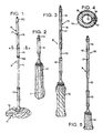
- the floor mop 8 of the present invention includes an elongate stick 10.
- a mop head 11 is attached to a lower end of the stick 10.
- a highly absorbent mop fabric 12 has one end 7 attached to the lower end of the stick 10 and the other end is attached to a sleeve or handle 13.
- An upper end of the stick 10 may have an attachment member 16 attached thereto.
- the groove of the attachment member 16 may also be defined on an extension that is longitudinally added to the length of the stick 10, or it may be defined on the mop stick itself.
- the handle 13 is freely shiftable along and rotatable about the stick 10.
- an upper handle may be rigidly secured to the stick 10 at a distance of about 35 centimeters from an upper end of the stick.
- this handle has been replaced with an upper handle 19 that is adapted to be in operative engagement with a helical groove 17 or such defined directly in the mop stick or in the elongate attachment member or sleeve 16 that is secured to the mop stick 10 that is described in detail below.
- the attachment member 16 or the mop stick itself has the helical groove 17 defined therein that extends from an upper portion 60 to a lower portion 62 of the attachment member 16 or on the mop stick correspondingly.
- An important feature of the attachment member 16 together with the upper handle 19 in operative engagement therewith is that they may be adapted to be mounted to a conventional twister mop stick (such as the SmartMop mop stick) as an accessory.
- the attachment member 16 should in this case be made sufficiently long so that the lower portion 62 of the attachment member covers the screw holes for mounting the prior art upper handle so that the holes may be used to attach the attachment member 16.
- the attachment member 16 may be made of a wide variety of materials including a plastic material that is suitable for conventional plastic forming processes.
- a low friction plastic may be used to form the attachment member 16 to make it easy to slide the handle 19 on the attachment member 16.
- This is one of the many advantages of having the groove defined in the attachment member, as opposed to directly in the mop stick itself. It is often not practical to mold the whole mop stick out of plastic.
- a relatively thick attachment member improves the mechanical strength of the attachment member 16.
- Another advantage of defining the helical groove or grooves in the attachment member is that the diameter of the attachment member 16 may be adjusted without having to make the whole stick of a thicker diameter. A thick stick is not only more expensive to make but also heavier. Additionally, if the helical groove of the attachment member is damaged, it is only necessary to replace the attachment member and not the whole stick.
- the helical groove may be defined directly in or on the upper end of the stick 10 also, which in turn has its own advantages.
- the details of the helical groove may be varied. For example, it may have a wave-shaped bottom and it may take the embodiment of a ridge or it may be a series of holes, cavities or elevations. If the helical groove is to be defined directly on the mop stick itself, it is possible to make holes along a helical outline, and, for example, let a cam follower take the shape of a cog wheel.
- the mop stick with a ridge or a series of elevations along a helical outline, either in one piece or by attaching the ridge or elevations to the mop stick.
- the ridge can be a spiral, preferably made of metal such as iron or aluminum, secured directly to the stick or an attachment member. This spiral could be fixed to the stick by inserting its bent ends into holes defined in the mop stick.
- a protrusion 18 (see Fig. 4) is disposed on an inside of the upper handle 19 so that the protrusion is in operative engagement with the helical groove 17 defined on an outside surface of the attachment member 16 or the mop stick 10 and so that the stick 10 is rotatable when the upper handle 19 is axially or longitudinally shifted along the helical groove.
- the slope of the helical groove may preferably vary along its length.
- an attachment member 64 has a helical groove 66 defined therein.
- the attachment member 64 has an upper portion 68 and a lower portion 70.
- the slope has an angle alpha at the lower portion 70 that is approximately 45 degrees relative to the longitudinal axis of the attachment member 64. It is to be understood that the angle alpha may be more or less than 45 degrees.
- the angle of the helical groove 66 may be gradually reduced as the helical groove extends from the lower portion 70 to the upper portion 68.
- the mop fabric provides a somewhat increasing resistance as the upper handle is moved axially upwardly to wring the mop fabric.
- the gradual reduction of the angle of the slope of the helical groove reduces the effort required to wring the mop fabric.
- the handle reaches an upper end segment 72, it stops due to the restraint of the twisted-up mop fabric, (or due to the fact that it has reached the end of the helical groove).
- the continued pull on the upper handle 19 causes the lower handle to approach the bottom end of the mop stick. This causes the ends of the twisted-up mop fabric to be pressed together. This may be regarded as a second phase of the wringing, caused by the one single motion of pulling the upper handle 19 upwards.
- this second wringing/squeezing phase is hereinafter often described as the user pushing a lower handle 73 toward a mop fabric 75 while the upper handle is held in its uppermost position, to further wring out water from the mop fabric 75, as best seen in Fig. 5.
- the first phase is the twisting of the mop fabric around the mop stick.
- the second phase is the pushing together of the ends of the twisted-up mop fabric.
- the helical groove may be a helical member that extends along the mop stick itself or along the attachment member and protrudes radially outwardly. If a helical ridge is used, then the upper handle may have either a relatively short conventional straight groove or a short helical groove defined therein to operatively engage the helical ridge. Variations with one or several rollers or similar rolling devices are also possible.
- the mop may include a locking mechanism on the upper handle so that the handle may be temporarily locked in a desired position along the mop stick.
- the various components are preferably positioned as is shown in Fig. 1.
- the upper handle 19 it is not necessary for the upper handle 19 to be in its lower position because the handle may also be disposed in an upper position along helical groove by means of a locking device.
- the upper handle 19 is usually in its lower position. If this is not the case, the handle is moved to its lower position (see Fig. 1), The lower handle 13 is then lifted so that the mop fabric of the mop head is extended along the stick (see Fig. 2).
- the upper handle 19 is moved upwardly, engaging the helical groove and turning the mop stick until the mop fabric is fully twisted (or until the uppermost end of the helical groove is reached, as best seen in Fig. 3).
- the continued pull on the halted upper handle 19 at this point causes the ends of the mop fabric to be pushed together, squeezing more water from the fabric and resulting in an excellent wringing result, as best seen in Fig. 5.
- An effective method for rinsing the mop is to immerse the mop head into water, after which the upper handle is gripped and moved from its lower position to its upper position. Then the mop head and the mop fabric are rotated and spread out by this upward movement of the handle 19.
- a twister mop wrung by the method and device herein described is therefor far more practical and easy to use than the prior art twister mops.
- the lower handle 13 may be pressed further against the mop fabric while the upper handle 19 is held in its tight uppermost position.
- the present invention is a substantial improvement over the prior art mops.
- the present invention may be provided as a completely new and fully equipped floor mop including the wringing mechanism or as a separate wringing accessory that is adapted to be mounted on the prior art mops of the type represented by the mop that is sold under the SMARTMOP trademark and similar mops.
- a helical groove and the protrusion have been employed to convert the translational movements to rotational movements. If desired, other mechanisms may be used to accomplish this conversion even though mechanisms based on at least one helical groove and a protrusion are often the easiest and the least expensive.
- the attachment member or the mop stick may have a polygon shaped cross section that is in operative engagement with the handle in such a way that the shifting of the handle in the axial direction also causes the stick to rotate.
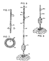
- FIG. 6 An alternative embodiment of the above cross section of the stick 10 or an attachment member attached to the stick is shown in Figs. 6 and 7.
- at least one land portion 22 is formed on a component 27 such as an attachment member mounted on the stick, or on the stick itself.
- a handle 29 includes at least one cam follower or land portion defined on the inside of the handle to operatively engage and cooperate with the land portion 22.
- the slope of the helical grooves preferably varies along the length of the wringing mechanism.
- this alternative embodiment functions in the same way as the earlier described embodiment, as shown in Figs. 1 to 5.
- the protrusion may take many embodiments, without departing from the spirit of this invention. It may be an immovable and integrated extension of the upper handle, or a rolling ball, or a rolling peg or a wheel, with or without cogs, depending on the embodiment of the helical groove. Or, if the groove itself is elevated as a ridge, the protrusion is adapted thereto, taking the form of a cavity of some sort, as discussed in a previous passage herein.
- the force of gravity caused by the weight of the stick (including eventually the attachment mechanism) and the mop fabric (inluding the cleaning liquid which is held therein) is substantially higher than the force of friction which is occurring during the relative movement of the upper handle and the stick.
- the mop fabric is wrung, but not pressed. This is due to the fact, that the force of gravity caused by the weight of the stick is much higher than the friction force.
- the lower handle will (nearly) not be shifted downwardly, while the upper handle is shifted upwardly.
- the force of gravity caused by the weight of the stick is more than two times the friction force, most preferably 5 to 100 times the friction force.
- the conversion mechanism includes a first conversion member 331 and a second conversion member 332.
- the first conversion member 331 is attached to the stick 310 and the second conversion member 332 is attached to the upper handle 319.
- the first and the second conversion members 331, 332 are disposed in an operative engagement such that a translational movement of the upper handle 319 along the stick 310 is converted in a rotational movement of the stick 310 relativ to the upper handle 319.
- the first and the second conversion members 331, 332 are helical members.
- the first conversion member 331 is defined in an attachment member 316 which is fixed to the stick 310.
- the attachment member 316 which is similar to the one described in figures 1 to 9, includes a plurality of protrusions 318 or buttons on the surface of the attachment member 316.
- the protrusions 318 or buttons are spaced one from another and are disposed on a helical line.
- the second conversion member 332 is diposed inside the upper handle 319 and is formed by an helically wound groove 317.
- the first conversion member 331 is a helical member. It is defined in an attachment member 316 which is fixed to the stick 310. It has the form of a twisted polygon 334.
- the polygon 334 shown in figure 11 is 6-sided, but could also have a minimum of 3 sides.
- the polygon 334 is at least 8-sided.
- the sides of the polygon 334 can be even, as shown in figure 11, but could also be concave. Further the corners of the polygon 334 could be rounded which will make the wringer easier to hold.
- the second conversion member 332 is disposed inside the upper handle 319 and is also formed by a hellically twisted polygon 335, which has approximately the same dimensions as the polygon 334 of the attachment member 316.
- the first and/or the second conversion members 331, 332 could be of the form of a hellically twisted ellipse instead of a polygon 334,335.
- first and the second conversion members 331, 332 are helical members.
- the first conversion member 331 is defined in an attachement 316 member which can be fixed to the stick.
- the second conversion member 332 is defined inside the upper handle 319.
- the first and the second conversion members 331, 332 have the form of splines 336, 337, the splines 336, 337 being helically twisted.
- a mechanism for converting translational movements to rotational movements such as a conversion mechanism having one or several rolling devices that a) include a friction surface or a friction promoting surface configuration, b) are disposed preferentiallly at the upper handle, c) are under load in the direction towards the stick and d) are in one manner or another angled in the same direction relative to the longitudinal axis of the stick so that when the upper handle is shifted along the stick, the stick is caused to rotate.
- the rolling device(s) may in this case be attached to the upper handle via a pressure adjusting mechanism having a sloping cam surface to engage a coplimentary cam surface on a roll holder to increase the application pressure of the rolling device(s)against the stick or the sleeve. This occurs when the handle is shifted in one direction and the pressure is reduced when the handle is shifted in the other opposite direction along the stick.
- the present invention automatically goes from the twisting of the mop fabric around the stick, to the lengthwise compression of the mop fabric, simply by a continued pull on the moving upper handle, after the point when the fabric is fully twisted around the stick.
- the point at which the twisting stops in its path, so that the terminating compression starts, is determined by the length of the mop fabric, and can be anywhere along the helix.
- a continued pull on the movable wringing handles of the prior art wringers on the other hand, will never allow the mop fabrics to move lengthwise without also being twisted by the factor decided by their helixes, nor will it allow them to be compressed in a direction opposite to the movement of the movable wringing handles.
Landscapes
- Cleaning Implements For Floors, Carpets, Furniture, Walls, And The Like (AREA)
Claims (24)
- Procédé d'essorage d'un balai à franges, le procédé comprenant les étapes consistant à :caractérisé par l'étape consistant àfournir un balai à franges (8) comprenant un manche allongé (10) et une tête à franges (11) incluant un tissu à franges (12) dont une extrémité (7) est fixée au manche (10);fournir une poignée inférieure (13) en engagement opérant avec le manche (10) et le tissu à franges (12);fournir une poignée supérieure (19) en engagement opérant avec le manche (10);fournir un mécanisme de conversion qui est conçu pour. convertir le mouvement de translation de la poignée supérieure (19) le long du manche (10) en un mouvement de rotation du manche;décaler vers le haut la poignée inférieure (13) en l'éloignant de la tête à franges (11) et étirer le tissu à franges (12);décaler vers le haut la poignée supérieure (19) de sorte que le mécanisme de conversion fait tourner le manche (10); et essorer le tissu à franges (12).
- Procédé d'essorage selon la revendication 1, dans lequel l'étape consistant à fournir un mécanisme de conversion comprend en outre l'étape consistant à fournir un premier et un deuxième éléments de conversion, dans lequel le premier élément est fixé au manche et dans lequel le deuxième élément de conversion est fixé à la poignée supérieure, dans lequel les premier et deuxième éléments de conversion sont disposés en engagement opérant et dans lequel les premier et/ou deuxième éléments de conversion sont des éléments hélicoïdaux.
- Procédé d'essorage selon la revendication 2, dans lequel le procédé comprend en outre l'étape consistant à doter l'élément hélicoïdal d'une première inclinaison à une extrémité supérieure de l'élément hélicoïdal et d'une deuxième inclinaison à une extrémité inférieure de l'élément hélicoïdal.
- Procédé d'essorage selon la revendication 3, dans lequel l'étape consistant à décaler la poignée supérieure comprend l'étape consistant à déplacer vers le haut la poignée supérieure en suivant la deuxième inclinaison et ensuite la première inclinaison.
- Procédé d'essorage selon l'une des revendications 1 à 4, dans lequel l'étape consistant à fournir un manche comprend en outre l'étape consistant à fournir un élément accessoire fixé au manche.
- Procédé d'essorage selon la revendication 5, dans lequel l'étape consistant à fournir un élément hélicoïdal comprend le fait que l'élément hélicoïdal soit défini dans l'élément accessoire.
- Procédé d'essorage selon l'une des revendications 2 à 4, dans lequel l'étape consistant à fournir un élément hélicoïdal comprend le fait que l'élément hélicoïdal soit défini dans le manche.
- Procédé d'essorage selon l'une des revendications 1 à 7, dans lequel l'étape consistant à fournir un élément hélicoïdal comprend le fait que l'élément hélicoïdal soit défini dans la poignée supérieure.
- Procédé d'essorage selon l'une des revendications 2 à 8, dans lequel l'étape consistant à fournir un élément hélicoïdal comprend le fait que l'élément hélicoïdal soit une gorge hélicoïdale.
- Procédé d'essorage selon l'une des revendications 2 à 9, dans lequel l'étape consistant à fournir un premier et un deuxième éléments de conversion comprend en outre l'étape consistant à fournir un deuxième élément qui est une extension faisant saillie vers l'intérieur, située à l'intérieur de la poignée supérieure, et dans lequel l'étape consistant à décaler la. poignée supérieure comprend l'étape consistant à permettre au deuxième élément de conversion de guider l'extension faisant saillie vers l'intérieur.
- Procédé d'essorage selon l'une des revendications 2 à 10, dans lequel l'étape consistant à fournir un élément hélicoïdal comprend le fait que l'élément hélicoïdal inclue une pluralité de saillies.
- Procédé d'essorage selon l'une des revendications 1 à 11, dans lequel l'étape consistant à décaler vers le haut la poignée supérieure comprend en outre les étapes consistant à déplacer la poignée supérieure dans une direction ascendante en l'éloignant du tissu à franges jusqu'à ce que le tissu à franges soit complètement étiré et essoré autour du manche.
- Procédé d'essorage selon l'une des revendications 1 à 12, dans lequel l'étape consistant à décaler vers le haut la poignée supérieure comprend en outre les étapes consistant à déplacer la poignée supérieure en l'éloignant du tissu à franges jusqu'à ce que la poignée supérieure atteigne une position dans laquelle le tissu à franges essoré empêche la poignée supérieure d'être davantage décalée.
- Procédé d'essorage selon l'une des revendications 1 à 13, dans lequel l'étape d'essorage comprend en outre l'étape consistant à continuer la traction sur la poignée supérieure après que le tissu à franges s'est enroulé autour du manche à balai à franges, de sorte que la poignée inférieure est poussée en s'éloignant de la poignée supérieure pour essorer davantage le tissu à franges.
- Procédé d'essorage selon l'une des revendications 1 à 14, dans lequel l'étape d'essorage comprend en outre l'étape consistant à continuer la traction dans une direction ascendante sur la poignée supérieure et pousser la poignée inférieure dans une position descendante après que le tissu à franges s'est complètement enroulé autour du manche à balai à franges, ce qui empêche la poignée supérieure d'être davantage décalée, et dans lequel une poussée supplémentaire vers le bas de la poignée inférieure entraíne la compression dans le sens de la longueur du tissu à franges.
- Balai à franges (8) comprenant :caractérisé en ce queun manche (10) possédant une extrémité inférieure, une extrémité supérieure opposée et un axe longitudinal s'étendant entre elles,un tissu à franges (12),une poignée inférieure (13) disposée à l'extrémité inférieure du manche (10), la poignée inférieure (13) pouvant être décalée axialement et en rotation par rapport au manche (10), le tissu à franges (12) étant fixé à l'extrémité inférieure du manche (10) et à la poignée inférieure (13),une poignée supérieure (19) en engagement opérant avec le manche (10);un mécanisme de conversion qui convertit un décalage longitudinal vers le haut de la poignée supérieure (19) en un mouvement de rotation du manche (10) pour essorer le tissu à franges (12),la force de gravité créée par le poids du manche (10), et en fin de compte d'un mécanisme accessoire (16), est supérieure à la force de frottement se produisant durant le déplacement relatif de la poignée supérieure (19) et du manche (10).
- Balai à franges selon la revendication 16, dans lequel le mécanisme de conversion comprend un premier et un deuxième éléments de conversion, dans lequel le premier élément de conversion est fixé au manche et dans lequel le deuxième élément de conversion est fixé à la poignée supérieure, et dans lequel les premier et deuxième éléments de conversion sont disposés en engagement opérant.
- Balai à franges selon la revendication 17, dans lequel le premier et/ou deuxième éléments de conversion sont des éléments hélicoïdaux.
- Balai à franges selon l'une des revendications 16 à 18, dans lequel un élément accessoire est fixé à l'extrémité supérieure du manche.
- Balai à franges selon la revendication 19, dans lequel l'élément hélicoïdal est défini dans l'élément accessoire.
- Balai à franges selon la revendication 19 ou 20, dans lequel l'élément hélicoïdal est une gorge hélicoïdale définie dans l'élément accessoire, dans lequel la poignée supérieure possède une saillie conçue pour engager de façon opérante la gorge hélicoïdale afin de faire tourner le manche lorsque la poignée supérieure est décalée le long de l'axe longitudinal du manche et dans lequel la saillie est guidée par la gorge hélicoïdale.
- Balai à franges selon la revendication 21, dans lequel la gorge hélicoïdale présente une inclinaison qui est variée de sorte que l'inclinaison a une première pente au niveau d'une portion supérieure du mécanisme accessoire et une deuxième pente au niveau d'une portion inférieure du mécanisme accessoire, et la première pente est différente de la deuxième pente.
- Balai à franges selon la revendication 21 ou 22, dans lequel la gorge hélicoïdale inclut un segment d'extrémité qui est substantiellement parallèle à l'axe longitudinal du manche.
- Balai à franges selon l'une des revendications 17 à 23, dans lequel le deuxième élément de conversion est disposé à l'intérieur de la poignée supérieure.
Applications Claiming Priority (3)
| Application Number | Priority Date | Filing Date | Title |
|---|---|---|---|
| US971001 | 1997-11-14 | ||
| US08/971,001 US5907883A (en) | 1997-02-05 | 1997-11-14 | Wringing method and wringing mechanism for floor mop |
| PCT/EP1998/007264 WO1999026523A1 (fr) | 1997-11-14 | 1998-11-13 | Procede et mecanisme d'essorage pour balai a franges |
Publications (2)
| Publication Number | Publication Date |
|---|---|
| EP1030586A1 EP1030586A1 (fr) | 2000-08-30 |
| EP1030586B1 true EP1030586B1 (fr) | 2004-01-07 |
Family
ID=25517803
Family Applications (1)
| Application Number | Title | Priority Date | Filing Date |
|---|---|---|---|
| EP98966236A Expired - Lifetime EP1030586B1 (fr) | 1997-11-14 | 1998-11-13 | Procede et mecanisme d'essorage pour balai a franges |
Country Status (8)
| Country | Link |
|---|---|
| US (1) | US5907883A (fr) |
| EP (1) | EP1030586B1 (fr) |
| CN (1) | CN1278708A (fr) |
| AU (1) | AU2266699A (fr) |
| CA (1) | CA2309441C (fr) |
| DE (1) | DE69821022T2 (fr) |
| ES (1) | ES2213934T3 (fr) |
| WO (1) | WO1999026523A1 (fr) |
Cited By (2)
| Publication number | Priority date | Publication date | Assignee | Title |
|---|---|---|---|---|
| USD597271S1 (en) | 2007-03-09 | 2009-07-28 | Carl Freudenberg Kg | Wringer for a cleaning implement |
| US8011055B2 (en) | 2006-06-01 | 2011-09-06 | Carl Freudenberg Kg | Cleaning implement |
Families Citing this family (16)
| Publication number | Priority date | Publication date | Assignee | Title |
|---|---|---|---|---|
| DE19916626C1 (de) * | 1999-04-13 | 2000-07-27 | Freudenberg Carl Fa | Wischmop mit Stiel |
| US6785927B2 (en) | 2001-12-20 | 2004-09-07 | Freudenberg Household Products | Roller mop |
| ITMI20032012A1 (it) * | 2003-10-16 | 2005-04-17 | Elesa Spa | Sistema di supporto a morsetti per dispositivi e componenti elettrici, elettronici, ottici e meccanici |
| US7269875B1 (en) * | 2003-11-19 | 2007-09-18 | David Brian Grimes | Cleaning apparatus |
| US7640616B2 (en) * | 2005-11-08 | 2010-01-05 | Brian Wesley Peterson | Mop with integral mop head wringing mechanism |
| TWM294916U (en) * | 2005-12-28 | 2006-08-01 | Jin-Yun Shr | Mop structure |
| AU2006200442B1 (en) * | 2006-02-02 | 2007-04-19 | Hsiao-Hung Chiang | Mop with Drying Mechanism |
| ES2340748B1 (es) * | 2007-09-03 | 2011-05-25 | Jesus Angel Oroz Garcia | Mango y cabezal direccional de fregona con mecanismo de ayuda al escurrido. |
| US8214963B2 (en) * | 2009-05-14 | 2012-07-10 | Tsung Mou Yu | Mop with spinning device |
| US9028379B2 (en) | 2009-06-23 | 2015-05-12 | Li Si Yang | Apparatus, system, and method for a fitness stick |
| BRPI1009634B1 (pt) * | 2009-06-23 | 2020-10-20 | Li si yang | aparelho de bastão de fitness |
| TWM374834U (en) | 2009-10-13 | 2010-03-01 | qing-jun Lin | Rotatable mop |
| US8220101B2 (en) * | 2009-12-29 | 2012-07-17 | Tuo Shen International Corporation Limited | Telescopically rotatable mop |
| CN101849808B (zh) * | 2010-06-20 | 2012-05-23 | 励土峰 | 手动甩干清洁装置 |
| US10687681B2 (en) * | 2015-05-08 | 2020-06-23 | Ingenious Designs Llc | Mop head with braided cord |
| CN111053576B (zh) * | 2019-12-31 | 2020-08-21 | 绵阳美科电子设备有限责任公司 | 使超声三维探头换能器往复转动的传动装置及其应用方法 |
Family Cites Families (19)
| Publication number | Priority date | Publication date | Assignee | Title |
|---|---|---|---|---|
| US1255804A (en) * | 1917-03-31 | 1918-02-05 | Carroline Shipherd | Dish-cleaner and mop. |
| US1514051A (en) * | 1922-08-03 | 1924-11-04 | Jumonville Charles | Mop |
| FR582968A (fr) * | 1923-06-20 | 1925-01-03 | Appareil porte-torchon permettant de tordre ce dernier | |
| FR570511A (fr) * | 1923-09-03 | 1924-05-02 | Perfectionnements aux appareils de nettoyage et spécialement à ceux permettant la torsion du torchon | |
| CH110249A (fr) * | 1923-09-12 | 1925-06-01 | Vanderschelden Louis | Appareil de nettoyage. |
| US1710190A (en) * | 1927-11-16 | 1929-04-23 | Parker Regan Corp | Combined mop holder and wringer |
| US1861795A (en) * | 1929-09-05 | 1932-06-07 | Hertzberg Patents Inc | Squeegee mop |
| US1870845A (en) * | 1930-05-06 | 1932-08-09 | Goldfinger Hyman | Mop |
| US2042892A (en) * | 1934-05-25 | 1936-06-02 | Granger Albert | Mop |
| US2066096A (en) * | 1935-03-07 | 1936-12-29 | Currie James Donald | Floor mop |
| US2230101A (en) * | 1940-04-15 | 1941-01-28 | Edward C Bakemeier | Mop holder and wringer |
| US2365437A (en) * | 1943-06-21 | 1944-12-19 | William G Pankonin | Mop |
| US2495846A (en) * | 1945-02-05 | 1950-01-31 | John M Johnson | Combined mop and wringer head |
| US2677838A (en) * | 1951-12-07 | 1954-05-11 | Albert M Jouban | Wringer mop |
| US4135274A (en) * | 1977-02-17 | 1979-01-23 | Catherine Freeman | Liquid applicator |
| GB2249947B (en) * | 1989-11-30 | 1994-08-31 | Peter Mckay | Twist action mop |
| DE4019480C1 (fr) * | 1990-06-19 | 1992-02-06 | Manfred 4790 Paderborn De Klotz | |
| US5722105A (en) * | 1995-12-28 | 1998-03-03 | Thomasson; Stig Ola | Floor mop and wringing mechanism therefor |
| DE29520612U1 (de) * | 1995-12-28 | 1996-02-15 | Thomasson, Stig Ola, Lund | Wischmop und Auswringteil hierfür |
-
1997
- 1997-11-14 US US08/971,001 patent/US5907883A/en not_active Expired - Lifetime
-
1998
- 1998-11-13 ES ES98966236T patent/ES2213934T3/es not_active Expired - Lifetime
- 1998-11-13 AU AU22666/99A patent/AU2266699A/en not_active Abandoned
- 1998-11-13 DE DE69821022T patent/DE69821022T2/de not_active Expired - Fee Related
- 1998-11-13 EP EP98966236A patent/EP1030586B1/fr not_active Expired - Lifetime
- 1998-11-13 WO PCT/EP1998/007264 patent/WO1999026523A1/fr not_active Ceased
- 1998-11-13 CN CN98811103.9A patent/CN1278708A/zh active Pending
- 1998-11-13 CA CA002309441A patent/CA2309441C/fr not_active Expired - Fee Related
Cited By (2)
| Publication number | Priority date | Publication date | Assignee | Title |
|---|---|---|---|---|
| US8011055B2 (en) | 2006-06-01 | 2011-09-06 | Carl Freudenberg Kg | Cleaning implement |
| USD597271S1 (en) | 2007-03-09 | 2009-07-28 | Carl Freudenberg Kg | Wringer for a cleaning implement |
Also Published As
| Publication number | Publication date |
|---|---|
| US5907883A (en) | 1999-06-01 |
| DE69821022D1 (de) | 2004-02-12 |
| AU2266699A (en) | 1999-06-15 |
| DE69821022T2 (de) | 2004-08-12 |
| CN1278708A (zh) | 2001-01-03 |
| ES2213934T3 (es) | 2004-09-01 |
| CA2309441C (fr) | 2008-09-16 |
| CA2309441A1 (fr) | 1999-06-03 |
| EP1030586A1 (fr) | 2000-08-30 |
| WO1999026523A1 (fr) | 1999-06-03 |
Similar Documents
| Publication | Publication Date | Title |
|---|---|---|
| EP1030586B1 (fr) | Procede et mecanisme d'essorage pour balai a franges | |
| US6125494A (en) | Self-wringing mop | |
| US20020092105A1 (en) | Mop with self-contained wringer sleeve | |
| US5850658A (en) | Wringable mop | |
| US5890253A (en) | Mop apparatus for unwinding the tangled strands of a mop head | |
| US5509163A (en) | Quick squeezing wringable mop | |
| US5722105A (en) | Floor mop and wringing mechanism therefor | |
| US5566417A (en) | Twistable wring mop with dual locking members | |
| CA2242824C (fr) | Balai a franges et essoreuse | |
| US20070226929A1 (en) | Wringable mop | |
| CN104939776B (zh) | 拖把的清洗方法及拖把的清洗和脱水方法 | |
| CA2305018C (fr) | Vadrouille avec mecanisme d'essorage | |
| US7093315B2 (en) | Twist mop | |
| GB2436519A (en) | Torsionally wringable mop | |
| USRE38380E1 (en) | Wringer mop | |
| US20060021171A1 (en) | Device for wringing out the material of domestic cleaning tools known as mops | |
| CN116392053B (zh) | 除水装置以及包括除水装置的清洁装置 | |
| GB2285391A (en) | Twist action mop | |
| CN109620076A (zh) | 一种免手洗平板拖把清洗桶 | |
| CN201312782Y (zh) | 一种方便拧干的拖把 | |
| US1700136A (en) | Mop | |
| CA2708621A1 (fr) | Balai a laver muni d'un dispositif d'essorage | |
| CN222787628U (zh) | 具有伸缩管的装置 | |
| CN218870200U (zh) | 一种二次拧水的拖把 | |
| CA2198506A1 (fr) | Balai a franges perfectionne a torsion |
Legal Events
| Date | Code | Title | Description |
|---|---|---|---|
| PUAI | Public reference made under article 153(3) epc to a published international application that has entered the european phase |
Free format text: ORIGINAL CODE: 0009012 |
|
| 17P | Request for examination filed |
Effective date: 20000427 |
|
| AK | Designated contracting states |
Kind code of ref document: A1 Designated state(s): BE DE DK ES FR GB IT NL SE |
|
| GRAG | Despatch of communication of intention to grant |
Free format text: ORIGINAL CODE: EPIDOS AGRA |
|
| 17Q | First examination report despatched |
Effective date: 20010611 |
|
| GRAG | Despatch of communication of intention to grant |
Free format text: ORIGINAL CODE: EPIDOS AGRA |
|
| GRAG | Despatch of communication of intention to grant |
Free format text: ORIGINAL CODE: EPIDOS AGRA |
|
| GRAH | Despatch of communication of intention to grant a patent |
Free format text: ORIGINAL CODE: EPIDOS IGRA |
|
| GRAS | Grant fee paid |
Free format text: ORIGINAL CODE: EPIDOSNIGR3 |
|
| GRAA | (expected) grant |
Free format text: ORIGINAL CODE: 0009210 |
|
| AK | Designated contracting states |
Kind code of ref document: B1 Designated state(s): BE DE DK ES FR GB IT NL SE |
|
| PG25 | Lapsed in a contracting state [announced via postgrant information from national office to epo] |
Ref country code: NL Free format text: LAPSE BECAUSE OF FAILURE TO SUBMIT A TRANSLATION OF THE DESCRIPTION OR TO PAY THE FEE WITHIN THE PRESCRIBED TIME-LIMIT Effective date: 20040107 Ref country code: BE Free format text: LAPSE BECAUSE OF FAILURE TO SUBMIT A TRANSLATION OF THE DESCRIPTION OR TO PAY THE FEE WITHIN THE PRESCRIBED TIME-LIMIT Effective date: 20040107 |
|
| REG | Reference to a national code |
Ref country code: GB Ref legal event code: FG4D |
|
| REF | Corresponds to: |
Ref document number: 69821022 Country of ref document: DE Date of ref document: 20040212 Kind code of ref document: P |
|
| PG25 | Lapsed in a contracting state [announced via postgrant information from national office to epo] |
Ref country code: SE Free format text: LAPSE BECAUSE OF FAILURE TO SUBMIT A TRANSLATION OF THE DESCRIPTION OR TO PAY THE FEE WITHIN THE PRESCRIBED TIME-LIMIT Effective date: 20040407 Ref country code: DK Free format text: LAPSE BECAUSE OF FAILURE TO SUBMIT A TRANSLATION OF THE DESCRIPTION OR TO PAY THE FEE WITHIN THE PRESCRIBED TIME-LIMIT Effective date: 20040407 |
|
| NLV1 | Nl: lapsed or annulled due to failure to fulfill the requirements of art. 29p and 29m of the patents act | ||
| REG | Reference to a national code |
Ref country code: ES Ref legal event code: FG2A Ref document number: 2213934 Country of ref document: ES Kind code of ref document: T3 |
|
| ET | Fr: translation filed | ||
| PLBE | No opposition filed within time limit |
Free format text: ORIGINAL CODE: 0009261 |
|
| STAA | Information on the status of an ep patent application or granted ep patent |
Free format text: STATUS: NO OPPOSITION FILED WITHIN TIME LIMIT |
|
| 26N | No opposition filed |
Effective date: 20041008 |
|
| PGFP | Annual fee paid to national office [announced via postgrant information from national office to epo] |
Ref country code: IT Payment date: 20071129 Year of fee payment: 10 |
|
| PGFP | Annual fee paid to national office [announced via postgrant information from national office to epo] |
Ref country code: GB Payment date: 20071121 Year of fee payment: 10 Ref country code: FR Payment date: 20071126 Year of fee payment: 10 |
|
| PGFP | Annual fee paid to national office [announced via postgrant information from national office to epo] |
Ref country code: DE Payment date: 20081128 Year of fee payment: 11 |
|
| PGFP | Annual fee paid to national office [announced via postgrant information from national office to epo] |
Ref country code: ES Payment date: 20081120 Year of fee payment: 11 |
|
| GBPC | Gb: european patent ceased through non-payment of renewal fee |
Effective date: 20081113 |
|
| PG25 | Lapsed in a contracting state [announced via postgrant information from national office to epo] |
Ref country code: IT Free format text: LAPSE BECAUSE OF NON-PAYMENT OF DUE FEES Effective date: 20081113 |
|
| REG | Reference to a national code |
Ref country code: FR Ref legal event code: ST Effective date: 20090731 |
|
| PG25 | Lapsed in a contracting state [announced via postgrant information from national office to epo] |
Ref country code: GB Free format text: LAPSE BECAUSE OF NON-PAYMENT OF DUE FEES Effective date: 20081113 |
|
| PG25 | Lapsed in a contracting state [announced via postgrant information from national office to epo] |
Ref country code: DE Free format text: LAPSE BECAUSE OF NON-PAYMENT OF DUE FEES Effective date: 20100601 |
|
| REG | Reference to a national code |
Ref country code: ES Ref legal event code: FD2A Effective date: 20110328 |
|
| PG25 | Lapsed in a contracting state [announced via postgrant information from national office to epo] |
Ref country code: ES Free format text: LAPSE BECAUSE OF NON-PAYMENT OF DUE FEES Effective date: 20110315 |
|
| PG25 | Lapsed in a contracting state [announced via postgrant information from national office to epo] |
Ref country code: FR Free format text: LAPSE BECAUSE OF NON-PAYMENT OF DUE FEES Effective date: 20081130 Ref country code: ES Free format text: LAPSE BECAUSE OF NON-PAYMENT OF DUE FEES Effective date: 20091114 |