EP1031390A1 - Vorrichtung zum Füllen von Behältern in einem System zum Giessen mit verlorenem Modell - Google Patents
Vorrichtung zum Füllen von Behältern in einem System zum Giessen mit verlorenem Modell Download PDFInfo
- Publication number
- EP1031390A1 EP1031390A1 EP99830106A EP99830106A EP1031390A1 EP 1031390 A1 EP1031390 A1 EP 1031390A1 EP 99830106 A EP99830106 A EP 99830106A EP 99830106 A EP99830106 A EP 99830106A EP 1031390 A1 EP1031390 A1 EP 1031390A1
- Authority
- EP
- European Patent Office
- Prior art keywords
- containers
- accordance
- sand
- models
- container
- Prior art date
- Legal status (The legal status is an assumption and is not a legal conclusion. Google has not performed a legal analysis and makes no representation as to the accuracy of the status listed.)
- Granted
Links
- 239000006260 foam Substances 0.000 title claims abstract 4
- 239000004576 sand Substances 0.000 claims abstract description 37
- 238000010114 lost-foam casting Methods 0.000 claims abstract description 6
- 230000015572 biosynthetic process Effects 0.000 claims description 15
- 238000005755 formation reaction Methods 0.000 claims description 15
- 230000000295 complement effect Effects 0.000 claims description 4
- 238000005266 casting Methods 0.000 description 15
- 239000000463 material Substances 0.000 description 4
- 210000000056 organ Anatomy 0.000 description 4
- 239000012530 fluid Substances 0.000 description 3
- 239000002184 metal Substances 0.000 description 3
- 230000002459 sustained effect Effects 0.000 description 3
- 239000004793 Polystyrene Substances 0.000 description 2
- 238000005056 compaction Methods 0.000 description 2
- 230000001276 controlling effect Effects 0.000 description 2
- 238000006073 displacement reaction Methods 0.000 description 2
- 238000000605 extraction Methods 0.000 description 2
- 238000000034 method Methods 0.000 description 2
- 229920002223 polystyrene Polymers 0.000 description 2
- 230000004913 activation Effects 0.000 description 1
- 239000000969 carrier Substances 0.000 description 1
- 238000006243 chemical reaction Methods 0.000 description 1
- 238000007654 immersion Methods 0.000 description 1
- 230000003287 optical effect Effects 0.000 description 1
- 230000002093 peripheral effect Effects 0.000 description 1
- 238000002360 preparation method Methods 0.000 description 1
- 230000001105 regulatory effect Effects 0.000 description 1
- 238000011144 upstream manufacturing Methods 0.000 description 1
Images

Classifications
-
- B—PERFORMING OPERATIONS; TRANSPORTING
- B22—CASTING; POWDER METALLURGY
- B22C—FOUNDRY MOULDING
- B22C9/00—Moulds or cores; Moulding processes
- B22C9/02—Sand moulds or like moulds for shaped castings
- B22C9/04—Use of lost patterns
- B22C9/046—Use of patterns which are eliminated by the liquid metal in the mould
-
- B—PERFORMING OPERATIONS; TRANSPORTING
- B22—CASTING; POWDER METALLURGY
- B22C—FOUNDRY MOULDING
- B22C15/00—Moulding machines characterised by the compacting mechanism; Accessories therefor
- B22C15/10—Compacting by jarring devices only
Definitions
- the present invention relates to devices for filling containers in lost-foam casting systems.
- Lost-foam casting technique represents an ever more widely employed foundry technique that is essentially based on the preparation of a model, generally made of polystyrene or some similar material, that exactly reproduces the characteristics of the piece to be cast.
- This model is inserted in a container (flask) filled with sand, which is then vibrated until the sand is distributed and compacted in such a manner as to adapt itself closely to and reproduce the exact shape of the model.
- Hot casting material typically molten metal
- the casting material dissolves the model and thus goes to occupy the space that was previously occupied by the model in the surrounding sand.
- the final result is therefore the obtainment of a casting, i.e. a workpiece, that exactly reproduces the shape of the model.
- the present invention comes to grips, first and foremost, with the problem of optimizing the operations that lead to the model being inserted or "drowned” in the sand prior to its compaction by vibration. This, in particular, as regards the need of avoiding such phenomena as breakage or displacement of the model (typically realized in the form of a cluster of smaller individual models).
- the invention also sets out to realize a filling device of the intelligent type, capable - in particular - of identifying the individual model and/or the container into which it has been inserted and thus to render possible, for example, selective specialization of the various processing operations, this to the point of arriving at treating each model/casting in accordance with a particular tailor-made processing "recipe".
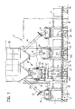
- Figure 1 represents a station 2 for filling the containers of a lost-foam casting plant or system.
- the plant in question could consist, for example, of the system described in greater detail in a European patent application filed on the same date by the same applicants.
- the models S are inserted into the containers C in which the casting operations are to be performed, the said containers being subsequently filled with sand and subjected to vibration, so that the sand will eventually become compacted and be in close contact with the outer surface of the said models S.
- the movement of the containers C is realized (from left to right, with respect to the viewing direction of Figure 1) in such a way as to produce a step-by-step forward motion of the containers below a main silo 20 designed for feeding sand by means of free fall to four successive filling substations.
- the said filling substations are consecutively numbered from 21 to 24 in the direction in which the containers C move forward beneath the silo 20.
- the containers C are usually placed on platform trolleys (carriers) 50 that move forward (under the action of movement control means not shown on the drawing) on rotating bodies 51 that could be, for example, rollers or wheels.
- the substation 21 can be defined as a prefilling station: here a certain quantity of sand F originating from within the silo 20 is fed through a duct 25 and an associated hopper 26 into the bottom part of the container C that at any given moment happens to be in the substation 21.
- the next substation has a somewhat more complex structure that will be described in greater detail further on.
- the polystyrene models or outlines S (usually in the form of model clusters, as already noted) are arranged inside the containers that have already had a certain quantity of sand filled into their bottom parts at the substation 21.
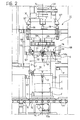
- the models S are usually taken from a feeder turntable (not shown in the figure) by means of a robot of which only the pick-up arm is shown by means of a dotted line in Figure 2, where it is identified by the letter R.
- model S normally consists of a model cluster provided with a grip formation T by means of which it can be picked up by the arm R of the robot to be sustained centrally, i.e. in a position that substantially coincides with the barycentre, by a positioning element indicated by the reference number 27 and subsequently to be described in greater detail.
- the container C receives, this time from the hopper 30, a further quantity of sand intended to cover the model S for a substantial part of its height.
- the container C is also lifted slightly in a vertical direction to detach it from the conveyor structure 50, while the lifting organs 31a (see Figure 3) that perform the said lifting action are caused to vibrate by means of a vibration device 32a.
- a vibration device 32a In this way the sand inside the container C is subjected to the necessary vibration and compaction action.
- Both the pick-up (gripping) organs 31a and the vibration device 32a are well known to the state of the art and need not therefore here be described in further detail.
- substations 23 and 24 The action of filling the container C with sand is completed at the subsequent substations indicated by 23 and 24.
- these two substations may be said to be intermediate between the complexity of substation 21 and that of substation 22.
- the substations 23 and 24 include respective ducts 33 and 34 for feeding sand from the silo 20 into the hoppers 35 and 36.
- the lifting organs and the vibration devices 32b and 32c which are substantially similar to the devices 31a and 32a that have already been mentioned in connection with substation 22.
- a mobile item of equipment 102 having the general structure of a projecting bracket.
- This bracket-like structure 102 sustains the hopper 30 below the bottom outlet opening 20a of the silo 20 and also extends downwards in the form of a cage structure 29 which sustains a frame 103 in a position that may be described as generically below the hopper 30.
- the said frame 103 sustains the previously mentioned positioning element 27 in a generically central position.
- the bracket-like structure 102 is preferably realized in the form of a square metal frame capable of carrying the hopper 30 through the intermediary of appropriate load cells 106 (which may be three in number, for example) on which there rest the correspondingly positioned bracket structures 107 projecting radially from the upper edge of the hopper 30.
- the load cells 106 therefore provide signals that indicate the quantity of sand present in the hopper 30 and, consequently, the quantity of sand that will eventually be transferred into the container C below the hopper.
- the frame 103 is suspended from the structure 102 by means of the legs 108, which do not in any way encumber the space within the frame 103 intended to be occupied by the positioning element 27.
- the said element includes a central hub 109 that carries a clamp 110 with a control unit 116.
- the hub 109 is sustained by a series of spokes 111, that connect it to an inner frame on which there is mounted at least one other clamp 112 with its own control unit 113.
- the frame 103 also carries, usually mounted on the said inner frame one or more centering formations 114.
- the said centering formations preferably include a fork element 114a, which - when the element 27 comes to be located (as will be described in greater detail further on) at the level of the upper rim of the container C - will engage with an appropriate counterpart projecting from that rim and will thus avoid undesired relative rotations.
- the operating units 116 and 113 of the clamps 110 and 112 are in their turn controlled, just like the unit that controls the aperture of the outlet opening 20a of the silo 20, by the unit 105 controlling the feeding of the sand from the bottom opening 104 of the hopper 30, the load cells 106 and the control unit of the jack 101, by a processor-type control unit K that may consist, for example, of a so-called PLC (acronym of Programmable Logic Controller) or some equivalent processing unit that controls (in accordance with criteria that are in themselves known and/or will be rendered obvious by the present description) the operation of these organs in a manner that is fully coordinated with the operation of the other parts of the plant, especially the robot R and the trolleys 50.
- PLC acronym of Programmable Logic Controller
- the operating unit 113 is preferably configured in such a manner that - with the system at rest - the return elements, springs for example, will keep the clamps 112 in their fully open position.
- the element 27 is not fixed to the frame 103, but rather rests freely - and, be it noted, in an exactly centred position - on the said frame, and can therefore become disengaged from the frame 103 by performing an upward movement relative to it.
- the operating cycle of the device constituting the substation 22 can be summarily described in the following terms.
- the device gets ready to receive a container C (already containing the quantity it received at the substation 21 on the upstream side) while the complex of parts sustained by the structure 102 is in the position shown by means of full lines in both Figure 2 and Figure 3.
- the fluid jack 101 keeps the entire structure at the upper end of its travel.
- the robot R has already picked up a model S and inserted the grip formation T with which it is provided into the clamps 110.
- the clamp is first maintained in its open position, which enables it to receive the said grip formation T, and is then closed around it, so that it will come to carry the model S.
- the robot arm R After releasing the model S it has just loaded into the device 22, the robot arm R returns towards the structure from which the models are picked up (which is typically of the turntable type and is not illustrated) in search of a new model S.
- the jack 101 is operated in such a way as to cause the entire supporting structure 102 to become gradually lowered towards the container C. This operation ensures that the model S will be lowered into the container C.
- the model S In the lowered position previously referred to, the model S usually comes to rest on top of the sand F already contained in the container C as a result of the pre-filling operation previously carried out at the substation 21.
- the said downward movement causes the clamps 112 to engage the upper rim of the container C.
- Activation of the unit 113 (likewise controlled by the PLC K) ensures that the clamps 112, originally open, will now tighten and grip the rim of the container C: the series of spokes 111, and therefore also the hub 109 they carry in a central position, will thus come to constitute what is de facto a single piece with the container C.
- the operating unit 105 controlling the bottom outlet of the hopper 30 can be activated to open the said outlet, so that the quantity of sand contained in it will now be discharged into the container C and there cover the model S.
- the said model is kept firmly in a fixed position with respect to the container C by means of the clamp 110 carried by the hub 109, which in its turn is linked by means of the spokes 111 to the clamps 112 that grip the rim of the container C.
- the descending sand will not therefore be able to cause any undesired displacements of the model S while the container is being filled. This even when the sand comes down in a rush of considerable intensity and/or when the model has surfaces orientated in such a manner as to exert a certain deflection action on the falling sand S (so that the model, by reaction, becomes subject to a certain fluid dynamic thrust).
- the container C complete with the model S and the further quantity of sand it received at the substation 22, can be subjected to the vibration operation, which is performed, in a known manner, with the help of the generator 32a while the formations 31a keep the container C lifted off the trolley 50 used to transport it.
- the said vibratory motion is applied to the body of the container while the model S is kept in a fixed position with respect to the container C by means of the various parts numbered 109 to 112. This ensures that the said vibratory motion, no matter how great its amplitude or intensity, will not be able either to displace the model S from its correct position or to cause a breakage of its gripping formation T, which in most cases will eventually define the channel through which the casting material will be poured into the container C.
- the lifting formations 31a will again lower the container C onto its trolley 50.
- the jack 101 can be operated in the direction that will cause the structure 102 to become raised, while both the clamps 110 and the clamps 112 are opened, so that the positioning element 27 becomes disengaged from both the rim of the container C and from the grip formation T of the model S, which has to remain within the container C.
- the frame 103 will therefore begin to rise and engage with the positioning element 27.
- centering formations 114a, 114b and their respective complementary formations ensures that the positioning element 27 will again become engaged with the frame 103 in an accurately defined position, so that the starting conditions indicated by means of the full lines in Figures 2 and 3 can eventually become exactly reconstituted.
- the container transport line can again be set in motion, so that the container C that has just been processed will be moved forward to substation 23 of Figure 1, while a new container will be moved from substation 21 to the device that constitutes substation 22.
- the robot R has the time it needs to insert a new model S into the clamp of the positioning element 27 and the bottom outlet 20a of the silo 20 can be opened again to reconstitute the sand supply needed in the hopper 30 for the next filling.
- the solution according to the invention therefore has the further advantage of permitting the operations of loading the models S and filling the hopper 30 to be carried out while the containers are being moved, thus avoiding possible idle times.
- the substation 22 that has just been described in detail usually forms part of a plant or system that, in addition to the said substation 22 and the container transport system 50, includes also other stations and substations for carrying out the following technological operations in due succession:
- the clusters constituting the models S are loaded with the help of a buffer turntable that presents them to the robot R, which then picks them up from the turntable and automatically feeds them into the sub-station 22.
- the solution according to the invention is such that these functions can be completely automated.
- matters can be arranged in such way that the robot R, immediately after picking up a model S from the turntable, presents it in front of an identification station consisting, for example, of a television camera P and an appropriate model recognition module of a known type and possibly resident in the control unit K.
- the identification station recognizes the model S (among a set of possible models) and thereupon informs the system of the particular recipe needed for this model. This can be done by means of an appropriate type identification signal generated, for example, in the control unit K.
- the model S is - as it were - paired with the container (which is provided with a plate T, which could be - for example - of the magnetic or optical reading type, on which the casting data, recipe included, can be memorized).
- a plate T which could be - for example - of the magnetic or optical reading type, on which the casting data, recipe included, can be memorized.
- an electronic reader informs the station in question of the contents of the container, thus enabling it to fall into line with the parameters of a particular recipe.
Landscapes
- Engineering & Computer Science (AREA)
- Mechanical Engineering (AREA)
- Filling Or Emptying Of Bunkers, Hoppers, And Tanks (AREA)
- Basic Packing Technique (AREA)
Priority Applications (3)
| Application Number | Priority Date | Filing Date | Title |
|---|---|---|---|
| EP99830106A EP1031390B1 (de) | 1999-02-26 | 1999-02-26 | Vorrichtung zum Füllen von Behältern in einem System zum Giessen mit verlorenem Schaummodell |
| DE69920652T DE69920652T2 (de) | 1999-02-26 | 1999-02-26 | Vorrichtung zum Füllen von Behältern in einem System zum Giessen mit verlorenem Schaummodell |
| US09/512,815 US6749004B1 (en) | 1999-02-26 | 2000-02-25 | Container-filling device for lost-foam casting systems |
Applications Claiming Priority (1)
| Application Number | Priority Date | Filing Date | Title |
|---|---|---|---|
| EP99830106A EP1031390B1 (de) | 1999-02-26 | 1999-02-26 | Vorrichtung zum Füllen von Behältern in einem System zum Giessen mit verlorenem Schaummodell |
Publications (2)
| Publication Number | Publication Date |
|---|---|
| EP1031390A1 true EP1031390A1 (de) | 2000-08-30 |
| EP1031390B1 EP1031390B1 (de) | 2004-09-29 |
Family
ID=8243295
Family Applications (1)
| Application Number | Title | Priority Date | Filing Date |
|---|---|---|---|
| EP99830106A Expired - Lifetime EP1031390B1 (de) | 1999-02-26 | 1999-02-26 | Vorrichtung zum Füllen von Behältern in einem System zum Giessen mit verlorenem Schaummodell |
Country Status (3)
| Country | Link |
|---|---|
| US (1) | US6749004B1 (de) |
| EP (1) | EP1031390B1 (de) |
| DE (1) | DE69920652T2 (de) |
Cited By (1)
| Publication number | Priority date | Publication date | Assignee | Title |
|---|---|---|---|---|
| CN121178848A (zh) * | 2025-11-26 | 2025-12-23 | 四川工宇智创科技有限公司 | 一种适用于板状容器装填的金属粉料自动装填设备 |
Families Citing this family (2)
| Publication number | Priority date | Publication date | Assignee | Title |
|---|---|---|---|---|
| CN109296362B (zh) * | 2018-08-31 | 2022-03-01 | 中国石油天然气股份有限公司 | 旋转填砂装置、应用于填砂模型的旋转填砂系统及方法 |
| CN112427601B (zh) * | 2020-11-23 | 2021-09-24 | 包头市晟裕机械制造有限责任公司 | 一种水玻璃砂造型加砂装置 |
Citations (5)
| Publication number | Priority date | Publication date | Assignee | Title |
|---|---|---|---|---|
| US4565227A (en) * | 1984-06-15 | 1986-01-21 | Outboard Marine Corporation | Process and apparatus for surrounding foam pattern with sand |
| US4768567A (en) * | 1987-09-03 | 1988-09-06 | General Motors Corporation | Sand fill apparatus for lost foam casting |
| JPS645640A (en) * | 1987-06-26 | 1989-01-10 | Sintokogio Ltd | Method and apparatus for burying lost foam pattern in full mold process |
| GB2209977A (en) * | 1987-09-19 | 1989-06-01 | Nissan Motor | Method of producing sand metal casting mold, by a plurality of alternate sand supply and vibration steps |
| US4947923A (en) * | 1988-04-14 | 1990-08-14 | Rikker Leslie D | Method and apparatus for evaporative pattern casting |
Family Cites Families (11)
| Publication number | Priority date | Publication date | Assignee | Title |
|---|---|---|---|---|
| US3868986A (en) * | 1974-01-04 | 1975-03-04 | Ford Motor Co | Pattern alignment means for use with lost foam molding process |
| US4454906A (en) * | 1980-12-04 | 1984-06-19 | General Kinematics Corporation | Vibratory method for packing foundry sand into a pattern prior to the pouring of molten metal |
| US4593739A (en) * | 1983-12-30 | 1986-06-10 | Outboard Marine Corporation | Method of and apparatus for packing sand around a mold pattern by vibration |
| US4600046A (en) * | 1984-01-04 | 1986-07-15 | Outboard Marine Corporation | Molding apparatus and process including sand compaction system |
| US4685504A (en) * | 1984-10-30 | 1987-08-11 | General Kinematics Corporation | Foundry sand feeding apparatus |
| US4736787B1 (en) * | 1987-06-29 | 1999-11-16 | Vulcan Engineering Co | Lost foam handling system |
| US4784206A (en) * | 1987-12-03 | 1988-11-15 | Combustion Engineering, Inc. | Sand vibration and compaction apparatus and method |
| US4844142A (en) * | 1988-05-31 | 1989-07-04 | Edge Clarence L | Lost foam sand casting apparatus |
| US4860816A (en) * | 1988-09-15 | 1989-08-29 | General Kinematics Corporation | Control system for vibratory apparatus |
| US4971135A (en) * | 1989-02-23 | 1990-11-20 | Outboard Marine Corporation | Lost foam casting apparatus |
| JPH10328783A (ja) * | 1997-05-29 | 1998-12-15 | Isuzu Motors Ltd | 鋳物砂の振動充填装置 |
-
1999
- 1999-02-26 DE DE69920652T patent/DE69920652T2/de not_active Expired - Fee Related
- 1999-02-26 EP EP99830106A patent/EP1031390B1/de not_active Expired - Lifetime
-
2000
- 2000-02-25 US US09/512,815 patent/US6749004B1/en not_active Expired - Fee Related
Patent Citations (5)
| Publication number | Priority date | Publication date | Assignee | Title |
|---|---|---|---|---|
| US4565227A (en) * | 1984-06-15 | 1986-01-21 | Outboard Marine Corporation | Process and apparatus for surrounding foam pattern with sand |
| JPS645640A (en) * | 1987-06-26 | 1989-01-10 | Sintokogio Ltd | Method and apparatus for burying lost foam pattern in full mold process |
| US4768567A (en) * | 1987-09-03 | 1988-09-06 | General Motors Corporation | Sand fill apparatus for lost foam casting |
| GB2209977A (en) * | 1987-09-19 | 1989-06-01 | Nissan Motor | Method of producing sand metal casting mold, by a plurality of alternate sand supply and vibration steps |
| US4947923A (en) * | 1988-04-14 | 1990-08-14 | Rikker Leslie D | Method and apparatus for evaporative pattern casting |
Non-Patent Citations (1)
| Title |
|---|
| PATENT ABSTRACTS OF JAPAN vol. 013, no. 170 (M - 817) 21 April 1989 (1989-04-21) * |
Cited By (1)
| Publication number | Priority date | Publication date | Assignee | Title |
|---|---|---|---|---|
| CN121178848A (zh) * | 2025-11-26 | 2025-12-23 | 四川工宇智创科技有限公司 | 一种适用于板状容器装填的金属粉料自动装填设备 |
Also Published As
| Publication number | Publication date |
|---|---|
| US6749004B1 (en) | 2004-06-15 |
| DE69920652T2 (de) | 2005-02-10 |
| EP1031390B1 (de) | 2004-09-29 |
| DE69920652D1 (de) | 2004-11-04 |
Similar Documents
| Publication | Publication Date | Title |
|---|---|---|
| CN1082859C (zh) | 带有双层浇注和冷却线的线型铸模输送系统 | |
| US4589467A (en) | Mold handling system | |
| CN1236880C (zh) | 铸造金属的方法和装置 | |
| EP2427283B1 (de) | Transportlinie zum transportieren einer metallschmelze | |
| US6725903B2 (en) | Automated casting system | |
| US4736787A (en) | Lost foam handling system | |
| EP1031390B1 (de) | Vorrichtung zum Füllen von Behältern in einem System zum Giessen mit verlorenem Schaummodell | |
| CN206842505U (zh) | 一种纱卷自动上架装置 | |
| EP2644515A1 (de) | Vorrichtung zum Leeren von Behältern | |
| CZ20022347A3 (cs) | Zařízení pro manipulaci s licími formami | |
| JP2002321051A (ja) | 鋳造方法及び鋳造ライン | |
| US3605869A (en) | Support means for ceramic shell moulds | |
| CN211687413U (zh) | 提升供料机及含该供料机的agv物料输送系统 | |
| US3150425A (en) | Flask handling equipment | |
| CA1172824A (en) | Apparatus for production of cores from fluidized sands in hot boxes | |
| JPS627524Y2 (de) | ||
| SU1003995A1 (ru) | Установка дл лить по выплавл емым модел м | |
| EP1918045B1 (de) | Giesssystem für hohe Produktivität | |
| JPS61154762A (ja) | ジヤケツト及びウエイトの移載装置 | |
| CN216806039U (zh) | 一种自动灌装工作站 | |
| CN210175944U (zh) | 一种螺栓生产线上料装置 | |
| JPH0237957A (ja) | 鋳物取出し移載装置 | |
| FR2911522A1 (fr) | Chaine de production automatisee de pieces metalliques et procede de moulage. | |
| EP0177644B1 (de) | Transportvorrichtung für Giessformen | |
| US4585048A (en) | Mold transfer assembly |
Legal Events
| Date | Code | Title | Description |
|---|---|---|---|
| PUAI | Public reference made under article 153(3) epc to a published international application that has entered the european phase |
Free format text: ORIGINAL CODE: 0009012 |
|
| AK | Designated contracting states |
Kind code of ref document: A1 Designated state(s): CH DE FR GB IT LI |
|
| AX | Request for extension of the european patent |
Free format text: AL;LT;LV;MK;RO;SI |
|
| RTI1 | Title (correction) |
Free format text: A DEVICE FOR FILLING CONTAINERS IN LOST-FOAM CASTING SYSTEMS |
|
| 17P | Request for examination filed |
Effective date: 20010129 |
|
| AKX | Designation fees paid |
Free format text: CH DE FR GB IT LI |
|
| 17Q | First examination report despatched |
Effective date: 20030617 |
|
| GRAP | Despatch of communication of intention to grant a patent |
Free format text: ORIGINAL CODE: EPIDOSNIGR1 |
|
| GRAS | Grant fee paid |
Free format text: ORIGINAL CODE: EPIDOSNIGR3 |
|
| GRAA | (expected) grant |
Free format text: ORIGINAL CODE: 0009210 |
|
| RAP1 | Party data changed (applicant data changed or rights of an application transferred) |
Owner name: FATA ALUMINIUM S.P.A. |
|
| AK | Designated contracting states |
Kind code of ref document: B1 Designated state(s): CH DE FR GB IT LI |
|
| PG25 | Lapsed in a contracting state [announced via postgrant information from national office to epo] |
Ref country code: LI Free format text: LAPSE BECAUSE OF FAILURE TO SUBMIT A TRANSLATION OF THE DESCRIPTION OR TO PAY THE FEE WITHIN THE PRESCRIBED TIME-LIMIT Effective date: 20040929 Ref country code: CH Free format text: LAPSE BECAUSE OF FAILURE TO SUBMIT A TRANSLATION OF THE DESCRIPTION OR TO PAY THE FEE WITHIN THE PRESCRIBED TIME-LIMIT Effective date: 20040929 |
|
| REG | Reference to a national code |
Ref country code: GB Ref legal event code: FG4D |
|
| REG | Reference to a national code |
Ref country code: CH Ref legal event code: EP |
|
| REF | Corresponds to: |
Ref document number: 69920652 Country of ref document: DE Date of ref document: 20041104 Kind code of ref document: P |
|
| PG25 | Lapsed in a contracting state [announced via postgrant information from national office to epo] |
Ref country code: GB Free format text: LAPSE BECAUSE OF NON-PAYMENT OF DUE FEES Effective date: 20050226 |
|
| REG | Reference to a national code |
Ref country code: CH Ref legal event code: PL |
|
| PLBE | No opposition filed within time limit |
Free format text: ORIGINAL CODE: 0009261 |
|
| STAA | Information on the status of an ep patent application or granted ep patent |
Free format text: STATUS: NO OPPOSITION FILED WITHIN TIME LIMIT |
|
| ET | Fr: translation filed | ||
| 26N | No opposition filed |
Effective date: 20050630 |
|
| GBPC | Gb: european patent ceased through non-payment of renewal fee |
Effective date: 20050226 |
|
| PGFP | Annual fee paid to national office [announced via postgrant information from national office to epo] |
Ref country code: DE Payment date: 20070118 Year of fee payment: 9 |
|
| PGFP | Annual fee paid to national office [announced via postgrant information from national office to epo] |
Ref country code: IT Payment date: 20070609 Year of fee payment: 9 |
|
| PGFP | Annual fee paid to national office [announced via postgrant information from national office to epo] |
Ref country code: FR Payment date: 20070228 Year of fee payment: 9 |
|
| REG | Reference to a national code |
Ref country code: FR Ref legal event code: ST Effective date: 20081031 |
|
| PG25 | Lapsed in a contracting state [announced via postgrant information from national office to epo] |
Ref country code: DE Free format text: LAPSE BECAUSE OF NON-PAYMENT OF DUE FEES Effective date: 20080902 |
|
| PG25 | Lapsed in a contracting state [announced via postgrant information from national office to epo] |
Ref country code: FR Free format text: LAPSE BECAUSE OF NON-PAYMENT OF DUE FEES Effective date: 20080229 |
|
| PG25 | Lapsed in a contracting state [announced via postgrant information from national office to epo] |
Ref country code: IT Free format text: LAPSE BECAUSE OF NON-PAYMENT OF DUE FEES Effective date: 20080226 |