EP1032743B1 - Selbstverriegelndes panikschloss - Google Patents
Selbstverriegelndes panikschloss Download PDFInfo
- Publication number
- EP1032743B1 EP1032743B1 EP99926357A EP99926357A EP1032743B1 EP 1032743 B1 EP1032743 B1 EP 1032743B1 EP 99926357 A EP99926357 A EP 99926357A EP 99926357 A EP99926357 A EP 99926357A EP 1032743 B1 EP1032743 B1 EP 1032743B1
- Authority
- EP
- European Patent Office
- Prior art keywords
- guide
- slide
- self
- bolt
- nut
- Prior art date
- Legal status (The legal status is an assumption and is not a legal conclusion. Google has not performed a legal analysis and makes no representation as to the accuracy of the status listed.)
- Expired - Lifetime
Links
- 230000003111 delayed effect Effects 0.000 claims description 2
- 230000006870 function Effects 0.000 description 14
- 230000005540 biological transmission Effects 0.000 description 6
- 108010063955 thrombin receptor peptide (42-47) Proteins 0.000 description 3
- 230000003213 activating effect Effects 0.000 description 1
- 230000001934 delay Effects 0.000 description 1
- 230000003993 interaction Effects 0.000 description 1
- 230000005226 mechanical processes and functions Effects 0.000 description 1
- 238000000034 method Methods 0.000 description 1
- 230000007659 motor function Effects 0.000 description 1
- 239000013641 positive control Substances 0.000 description 1
Images


Classifications
-
- E—FIXED CONSTRUCTIONS
- E05—LOCKS; KEYS; WINDOW OR DOOR FITTINGS; SAFES
- E05B—LOCKS; ACCESSORIES THEREFOR; HANDCUFFS
- E05B47/00—Operating or controlling locks or other fastening devices by electric or magnetic means
- E05B47/0001—Operating or controlling locks or other fastening devices by electric or magnetic means with electric actuators; Constructional features thereof
- E05B47/0012—Operating or controlling locks or other fastening devices by electric or magnetic means with electric actuators; Constructional features thereof with rotary electromotors
-
- E—FIXED CONSTRUCTIONS
- E05—LOCKS; KEYS; WINDOW OR DOOR FITTINGS; SAFES
- E05B—LOCKS; ACCESSORIES THEREFOR; HANDCUFFS
- E05B59/00—Locks with latches separate from the lock-bolts or with a plurality of latches or lock-bolts
-
- E—FIXED CONSTRUCTIONS
- E05—LOCKS; KEYS; WINDOW OR DOOR FITTINGS; SAFES
- E05B—LOCKS; ACCESSORIES THEREFOR; HANDCUFFS
- E05B65/00—Locks or fastenings for special use
- E05B65/10—Locks or fastenings for special use for panic or emergency doors
- E05B65/1086—Locks with panic function, e.g. allowing opening from the inside without a ley even when locked from the outside
-
- E—FIXED CONSTRUCTIONS
- E05—LOCKS; KEYS; WINDOW OR DOOR FITTINGS; SAFES
- E05B—LOCKS; ACCESSORIES THEREFOR; HANDCUFFS
- E05B15/00—Other details of locks; Parts for engagement by bolts of fastening devices
- E05B15/10—Bolts of locks or night latches
- E05B15/102—Bolts having movable elements
- E05B2015/105—Two pivoting latch elements with opposite inclined surfaces mounted on one slidable main latch-piece
-
- E—FIXED CONSTRUCTIONS
- E05—LOCKS; KEYS; WINDOW OR DOOR FITTINGS; SAFES
- E05B—LOCKS; ACCESSORIES THEREFOR; HANDCUFFS
- E05B47/00—Operating or controlling locks or other fastening devices by electric or magnetic means
- E05B47/0001—Operating or controlling locks or other fastening devices by electric or magnetic means with electric actuators; Constructional features thereof
- E05B2047/0014—Constructional features of actuators or power transmissions therefor
- E05B2047/0018—Details of actuator transmissions
- E05B2047/0024—Cams
-
- E—FIXED CONSTRUCTIONS
- E05—LOCKS; KEYS; WINDOW OR DOOR FITTINGS; SAFES
- E05B—LOCKS; ACCESSORIES THEREFOR; HANDCUFFS
- E05B63/00—Locks or fastenings with special structural characteristics
- E05B63/18—Locks or fastenings with special structural characteristics with arrangements independent of the locking mechanism for retaining the bolt or latch in the retracted position
- E05B63/20—Locks or fastenings with special structural characteristics with arrangements independent of the locking mechanism for retaining the bolt or latch in the retracted position released automatically when the wing is closed
- E05B2063/207—Automatic deadlocking
-
- E—FIXED CONSTRUCTIONS
- E05—LOCKS; KEYS; WINDOW OR DOOR FITTINGS; SAFES
- E05B—LOCKS; ACCESSORIES THEREFOR; HANDCUFFS
- E05B63/00—Locks or fastenings with special structural characteristics
- E05B63/18—Locks or fastenings with special structural characteristics with arrangements independent of the locking mechanism for retaining the bolt or latch in the retracted position
- E05B63/20—Locks or fastenings with special structural characteristics with arrangements independent of the locking mechanism for retaining the bolt or latch in the retracted position released automatically when the wing is closed
Definitions
- the invention relates to a self-locking panic lock with a spring-loaded Latch, a spring-loaded latch and a spring-loaded Auxiliary trap, which is a motor and mechanical in the longitudinal direction the lock movable slide is locked when the bolt is closed, the slide being spring-loaded when the bolt is included time and when including the auxiliary trap and the trap Delays the locking bar release and the bias of the slide motor and mechanical both by means of a cylinder and key bit as well as by means of an actuating lever pivotable by means of a nut takes place, which as a two-armed, on a pivot of the Lock plate mounted lever is formed, the first lever arm one with a contact surface of the slide or add-on parts of the same has corresponding contact surface.
- From DE 196 09 484 C2 is one with an inside handle and one Mortise lock with two-part lock nut known that includes a panic function.
- the castle is under other from an interchangeable upper part on the lock nut and an interchangeable lower part guided on the bolt.
- the Interchangeable lower part By pressing the Interchangeable lower part by means of one arranged on the inner half of the nut Switch lever, the nut halves can be locked together and the Panic function can be switched on and off. A motor force transmission on the switch lever is not disclosed.
- DE 39 38 655 A1 describes an electromechanical door lock, which is also designed as a self-locking panic lock.
- the trigger must be a follow-up link designated, rigidly connected to the press lever provided with which the slide referred to as a power transmission member into a such position can be moved that the latch is included and the door can be opened from the inside.
- the optional Inclusion of the bolt by motor or mechanically takes place via in separate areas arranged in different areas of the castle Components, the respective component only the motor or mechanical Function.
- the object of the invention is in a castle of the aforementioned To develop the mechanics required for the panic function that by means of a single one must cooperate with the presser Component both mechanically and by motor Opening or closing the door is made possible.
- the invention solves the problem with a self-locking Panic lock of the type mentioned at the beginning, i.e. under use a two-armed actuating lever cooperating with the nut in that the second lever arm one with the nut or attachments has the same corresponding backdrop and another Has positive guidance with the gear end of a motor Drive can work together.
- the actuating lever serving as a panic lever is thus assigned a double function, namely on the one hand as by push-button actuation mechanically operated panic lever and on the other hand as last, the panic function of a motor loaded gear train.
- the panic function of a motor loaded gear train For either motorized or mechanical actuation of the slide for the purpose of locking the bolt no separate components are required.
- the second lever arm While in a known manner the first lever arm of the operating lever via a contact surface assigned to it, the slide during the bolt feed lifts into a locked position, the second lever arm according to the invention an inner link guide and an outer positive guide on, the inner backdrop guide the forced guidance for a the guide pin arranged on the nut and the external positive guidance the positive guidance for the gear end of the motor Drive forms.
- the second lever arm is thus the one described above Assigned double function, i.e. on the one hand, its structural training permits the mechanical actuation by a lever handle or the like. and on the other hand, the motor actuation by the transmission end member of the Gear train.
- the vertices of the inner slide guide the rest stops form the nut for the guide pin, which when actuated by the handle is forcibly guided within the triangular backdrop.
- this interacts with the external positive guidance Transmission end member of the motor drive is advantageous, a switching cam arranged in a rotationally fixed manner on a transmission output pinion, the outer positive guidance and the switching cam corresponding Have contact surfaces, so that the switching cam when motorized Actuation forces the actuating lever to pivot, to lift the slide to the required locking position leads.
- the nut - for example as divided, optionally connectable nut halves - in interaction with other components known from DE 196 26 745 C1 a lock device the invention also in such locks is applicable in which, in addition to the panic function, a Switching function, a permanent open function or the like. Is desired.
- the exemplary embodiments shown are only the components relevant to the invention are shown; i.e. the nut shown in one piece in the drawings is usually in two parts trained to allow opening of the door from the inside and thus ensuring the panic function while opening the door from the outside with the bolt locked using the lever handle not possible.
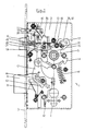
- the mortise lock 1 designed as a panic lock according to FIGS to 3 has a lock plate 2, a face plate 3, a lock cylinder contour 4, a recess 5 for the pusher dome, not shown, one through a latch spring 7 loaded latch 6, one by a locking spring 9 acted bolt 8, an acted upon by an auxiliary latch spring 11 Auxiliary trap 10 and one acted upon by a slide spring 13 Slide open.
- Figure 1 shows the mortise lock 1 with the door closed. i.e. the bolt 8 is pre-locked and the latch 6 is locked.
- the Locking of the trap 6 takes place via a guided in slot guides 40 Clamping plate 38, which has a locking surface, not specified Fall shank 45 in the position shown secures against inclusion.
- the clamping plate 38 is in the direction of arrow X by the auxiliary latch spring 11 applied.
- the slider 12 is in the image plane seen in its lower position.
- the lock cylinder bit grips a cam 43 on the bolt 8, so that the slide 12 is brought into its upper locking position can be in which he with a nose 46 a stop 47 of the auxiliary trap 10 backfires (see Figure 2).
- the actuating lever 15 is designed as a two-armed lever, the first lever arm 16 with a contact surface 21 a pin 20 on the slide 12 behind, the pin 20 practically a contact surface 19 and so that the counter surface for the contact surface 21 of the first lever arm forms.
- the second lever arm 17 of the actuating lever 15 has an inner link guide 29, which is approximately in the form of a triangle designated 32 is formed, and the vertices referred to as rest stops and are given the reference numbers 33, 34, 35.
- At 31 is on the nut 14th arranged guide pin, which in the inner link guide 29 is positively guided
- Figure 2 shows that when pressed the nut in the clockwise direction by about 25 ° of the guide pin 31 migrates from the rest point 35 into the rest point 34, the slide 12 raised, the bolt 8 enclosed and the latch 6 released, while the slide 12 in its upper position (see nose on Slide 46 and stop 47 on the auxiliary latch) engages.
- Figure 2 shows thus the opening process
- Figure 3 shows the situation with the door open and latched slide 12.
- the auxiliary latch 10 releases the slide 12, so that delayed in a known manner depending on the release of the slider 12 by the latch 6 of the locking bar 8 automatically can be done.
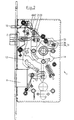
- the operating lever 15 next to the inner link guide 29 has an outer positive guide 30, by means of which the actuating lever 15 can be operated by motor.
- the pinion 27 forms the drive pinion and is non-rotatable connected to a switch cam 28 which, with reference to FIG Figure 4 contacted the outer positive guide 30 in a left-turning sense.
- the contact surface of the switching cam 28 on the outer positive guidance 30 is denoted by 36 according to FIG. 5; the contact surface of the outer positive guidance 30 with 37.
- the lock function 5 corresponds to the function according to FIG. 3, i.e. at the When the door is closed, the latch 3 is closed, the guide pin 48 of the bolt 8 in the slot guide 44 in a known manner of the slide 12 is positively guided.
- the invention turns into a self-locking panic lock proposed, in which the actuation of the bolt elements (bolt 8 and Trap 6) either mechanically or motorized over a single both on the lock plate 2 and on the nut 14 mounted operating lever 15 can be done.
Landscapes
- Business, Economics & Management (AREA)
- Emergency Management (AREA)
- Lock And Its Accessories (AREA)
- Connection Of Plates (AREA)
Description
- 1
- Einsteckschloß
- 2
- Schloßblech
- 3
- Stulp
- 4
- Schließzylinderkontur
- 5
- Ausnehmung
- 6
- Falle
- 7
- Fallenfeder
- 8
- Riegel
- 9
- Riegelfeder
- 10
- Hilfsfalle
- 11
- Hilfsfallenfeder
- 12
- Schieber
- 13
- Schieberfeder
- 14
- Nuß
- 15
- Betätigungshebel
- 16
- Erster Hebelarm
- 17
- Zweiter Hebelarm
- 18
- Drehzapfen
- 19
- Anlagefläche
- 20
- Zapfen
- 21
- Anlagefläche
- 22
- Getriebeendglied
- 23
- Motorischer Antrieb
- 24
- Ritzel
- 25
- Ritzel
- 26
- Ritzel
- 27
- Abtriebsritzel
- 28
- Schaltnocken
- 29
- Innere Kulissenführung
- 30
- Äußere Zwangsführung
- 31
- Führungszapfen
- 32
- Dreieck
- 33
- Raststellen
- 34
- Raststellen
- 35
- Raststellen
- 36
- Anlagefläche
- 37
- Anlagefläche
- 38
- Klemmplatte
- 39
- Nase
- 40
- Langlochführung
- 41
- Rückstellfeder
- 42
- Anschlag
- 43
- Nocken
- 44
- Schlitzführung
- 45
- Fallenschaft
- 46
- Nase
- 47
- Anschlag
- 48
- Führungszapfen
- X
- Pfeilrichtung
Claims (6)
- Selbstverriegelndes Panikschloß mit einer federbelasteten Falle (6), einem federbelasteten Riegel (8) und einer federbelasteten Hilfsfalle (10), welche einen motorisch und mechanisch in Längsrichtung des Schlosses bewegbaren Schieber (12) bei rückgeschlossenem Riegel (8) arretiert, wobei der Schieber (12) beim Einschließen des Riegels (8) federbelastet vorgespannt wird und beim Einschließen der Hilfsfalle (10) und der Falle (6) zeitlich verzögert den Riegelausschluß freigibt und die Vorspannung des Schiebers (12) motorisch und mechanisch sowohl mittels eines Zylinder- und Schlüsselbartes als auch mittels eines mittels einer Nuß (14) verschwenkbaren Betätigungshebels (15) erfolgt, welcher als zweiarmiger, an einem Drehzapfen (18) des Schloßbleches (2) gelagerter Hebel ausgebildet ist, dessen erster Hebelarm (16) eine mit einer Anlagefläche (19) des Schiebers (12) oder Anbauteilen desselben korrespondierende Anlagefläche (21) aufweist, dadurch gekennzeichnet, dass der zweite Hebelarm (17) eine mit der Nuß (14) bzw. Anbauteilen der selben korrespondierende Kulissenführung (29) aufweist und eine weitere Zwangsführung (30) ausweist, die mit dem Getriebeendglied (22) eines motorischen Antriebes (23) zusammen wirken kann.
- Selbstverriegelndes Panikschloß nach Anspruch 1, dadurch gekennzeichnet, dass der zweite Hebelarm (17) eine innere Kulissenführung (29) und eine äußere Zwangsführung (30) aufweist, wobei die innere Kulissenführung (29) die Zwangsführung für einen an der Nuß (14) angeordneten Führungszapfen (31) und die äußere Zwangsführung (30) die Zwangsführung für das Getriebeendglied (22) des motorischen Antriebs (23) bildet.
- Selbstverriegelndes Panikschloß nach den Ansprüchen 1 oder 2, dadurch gekennzeichnet, dass die innere Kulissenführung (29) etwa die Kontur eines Dreiecks (32) aufweist.
- Selbstverriegelndes Panikschloß nach Anspruch 3, dadurch gekennzeichnet, dass die Scheitelpunkte der inneren Kulissenführung (29) Raststellen (33, 34, 35) für den Führungszapfen (31) der Nuß (14) bilden.
- Selbstverriegelndes Panikschloß nach einem der Ansprüche 1 bis 4, dadurch gekennzeichnet, dass das Getriebeendglied (22) des motorischen Antriebs (23) ein drehfest an einem Getriebeabtriebsritzel (27) angeordneter Schaltnocken (28) ist.
- Selbstverriegelndes Panikschloß nach Anspruch 5, dadurch gekennzeichnet, dass die äußere Zwangsführung (30) und der Schaltnocken (28) korrespondierende Anlageflächen (36, 37) aufweisen.
Applications Claiming Priority (3)
| Application Number | Priority Date | Filing Date | Title |
|---|---|---|---|
| DE19827516 | 1998-06-22 | ||
| DE19827516A DE19827516C2 (de) | 1998-06-22 | 1998-06-22 | Selbstverriegelndes Panikschloß |
| PCT/EP1999/003511 WO1999067489A1 (de) | 1998-06-22 | 1999-05-21 | Selbstverriegelndes panikschloss |
Publications (2)
| Publication Number | Publication Date |
|---|---|
| EP1032743A1 EP1032743A1 (de) | 2000-09-06 |
| EP1032743B1 true EP1032743B1 (de) | 2003-05-07 |
Family
ID=7871495
Family Applications (1)
| Application Number | Title | Priority Date | Filing Date |
|---|---|---|---|
| EP99926357A Expired - Lifetime EP1032743B1 (de) | 1998-06-22 | 1999-05-21 | Selbstverriegelndes panikschloss |
Country Status (4)
| Country | Link |
|---|---|
| EP (1) | EP1032743B1 (de) |
| AT (1) | ATE239847T1 (de) |
| DE (2) | DE19827516C2 (de) |
| WO (1) | WO1999067489A1 (de) |
Cited By (3)
| Publication number | Priority date | Publication date | Assignee | Title |
|---|---|---|---|---|
| EP1970507A2 (de) | 2007-03-13 | 2008-09-17 | Dorma Gmbh & Co. Kg | Panikschloss |
| DE102008014369A1 (de) | 2008-03-17 | 2009-09-24 | Dorma Gmbh & Co Kg | Türschloss mit einer elektromagnetischen Offenhaltung |
| EP4206429A1 (de) | 2022-01-04 | 2023-07-05 | ASSA ABLOY Sicherheitstechnik GmbH | Selbstverriegelndes schloss mit motorischer entriegelung |
Families Citing this family (11)
| Publication number | Priority date | Publication date | Assignee | Title |
|---|---|---|---|---|
| DE19858174C2 (de) | 1998-12-17 | 2001-05-10 | Dorma Gmbh & Co Kg | Türschloß |
| IL146740A0 (en) * | 2001-11-26 | 2002-07-25 | Mul T Lock Security Prod Ltd | Locking amplifier |
| DE10359804A1 (de) * | 2003-12-19 | 2005-07-14 | Aug. Winkhaus Gmbh & Co. Kg | Antriebseinrichtung für einen Treibstangenbeschlag |
| DE102004034530B3 (de) * | 2004-07-15 | 2005-11-24 | Dorma Gmbh + Co. Kg | Elektromechanisches Türschloss |
| DE102004034529B3 (de) * | 2004-07-15 | 2006-04-20 | Dorma Gmbh + Co. Kg | Elektromechanisches Türschloss |
| CN100447366C (zh) * | 2005-12-05 | 2008-12-31 | 吴斐 | 具有自锁结构的电子锁锁芯 |
| CN2869236Y (zh) * | 2006-03-15 | 2007-02-14 | 张雪梅 | 一种防撬防锯的电动门锁 |
| DE102006060450A1 (de) * | 2006-12-19 | 2008-06-26 | Dorma Gmbh + Co. Kg | Selbstverriegelndes, elektromechanisches Panikschloss |
| DE102006060449A1 (de) * | 2006-12-19 | 2008-06-26 | Dorma Gmbh + Co. Kg | Selbstverriegelndes Panikschloss |
| CN107605284B (zh) * | 2017-10-31 | 2022-09-02 | 无锡瑞林智能科技有限公司 | 自吸侧门锁开锁离合机构 |
| CN113027246B (zh) * | 2021-03-26 | 2022-07-29 | 深圳Tcl新技术有限公司 | 锁体及其控制方法、计算机可读存储介质 |
Family Cites Families (6)
| Publication number | Priority date | Publication date | Assignee | Title |
|---|---|---|---|---|
| DE3806422A1 (de) * | 1988-02-29 | 1989-09-07 | Geco Sicherungstechnik | Schloss mit motor- und schliessbartantrieb |
| FI83802C (fi) * | 1988-11-25 | 1991-08-26 | Abloy Security Ltd Oy | Elektromekaniskt doerrlaos. |
| ES2115191T3 (es) * | 1994-02-21 | 1998-06-16 | Hellmuller & Zingg Ag | Cerradura de puerta. |
| DE19514742A1 (de) * | 1995-04-21 | 1996-10-24 | Geco Systemtechnik Gmbh | Rohrrahmenschloß |
| DE19609484C2 (de) * | 1996-03-12 | 1998-03-12 | Dorma Gmbh & Co Kg | Einsteckschloß |
| DE19626752C2 (de) * | 1996-07-03 | 1998-07-30 | Dorma Gmbh & Co Kg | Selbstverriegelndes Einsteckschloß |
-
1998
- 1998-06-22 DE DE19827516A patent/DE19827516C2/de not_active Expired - Lifetime
-
1999
- 1999-05-21 WO PCT/EP1999/003511 patent/WO1999067489A1/de not_active Ceased
- 1999-05-21 DE DE59905440T patent/DE59905440D1/de not_active Expired - Lifetime
- 1999-05-21 EP EP99926357A patent/EP1032743B1/de not_active Expired - Lifetime
- 1999-05-21 AT AT99926357T patent/ATE239847T1/de not_active IP Right Cessation
Cited By (7)
| Publication number | Priority date | Publication date | Assignee | Title |
|---|---|---|---|---|
| EP1970507A2 (de) | 2007-03-13 | 2008-09-17 | Dorma Gmbh & Co. Kg | Panikschloss |
| DE102007012613A1 (de) | 2007-03-13 | 2008-09-18 | Dorma Gmbh + Co. Kg | Panikschloss |
| DE102007012613B4 (de) * | 2007-03-13 | 2018-03-08 | Dormakaba Deutschland Gmbh | Panikschloss |
| DE102008014369A1 (de) | 2008-03-17 | 2009-09-24 | Dorma Gmbh & Co Kg | Türschloss mit einer elektromagnetischen Offenhaltung |
| DE102008014369B4 (de) | 2008-03-17 | 2018-12-27 | Dormakaba Deutschland Gmbh | Türschloss mit einer elektromagnetischen Offenhaltung |
| EP4206429A1 (de) | 2022-01-04 | 2023-07-05 | ASSA ABLOY Sicherheitstechnik GmbH | Selbstverriegelndes schloss mit motorischer entriegelung |
| DE102022100121A1 (de) | 2022-01-04 | 2023-07-06 | Assa Abloy Sicherheitstechnik Gmbh | Selbstverriegelndes Schloss mit motorischer Entriegelung |
Also Published As
| Publication number | Publication date |
|---|---|
| DE19827516A1 (de) | 1999-12-23 |
| ATE239847T1 (de) | 2003-05-15 |
| EP1032743A1 (de) | 2000-09-06 |
| DE59905440D1 (de) | 2003-06-12 |
| DE19827516C2 (de) | 2000-05-18 |
| WO1999067489A1 (de) | 1999-12-29 |
Similar Documents
| Publication | Publication Date | Title |
|---|---|---|
| EP1932989B1 (de) | Schliessanlage für Türen, Fenster oder dergleichen, insbesondere Treibstangenschloss mit Panikfunktion und Mehrpunktverriegelung | |
| EP0472774B1 (de) | Feststellsystem | |
| DE10202088B4 (de) | Schloss | |
| DE102006011263B4 (de) | Verriegelungssystem für eine Tür | |
| EP1032743B1 (de) | Selbstverriegelndes panikschloss | |
| DE19652601C1 (de) | Ent- und Verriegelung für eine einen Standflügel und einen Gangflügel aufweisende Tür | |
| EP1932990A2 (de) | Schliessanlage für Türen, Fenster oder dergleichen, insbesondere Treibstangenschloss mit Panikfunktion und Mehrpunktverriegelung | |
| DE19626745C1 (de) | Selbstverriegelndes Panikschloß | |
| EP1574644A2 (de) | Schliessanlage für Türen, Fenster oder dergleichen, insbesonde Treibstangenschloss mit Panikfunktion und Mehrpunktverriegelung | |
| EP0954667B1 (de) | Schloss mit falle für tür oder fenster | |
| DE3425565A1 (de) | Treibstangenschloss | |
| EP1056915A1 (de) | Türschloss | |
| DE202009016137U1 (de) | Treibstangenschloss mit Panikfunktion und Mehrfachverriegelung | |
| DE202008018160U1 (de) | Türschloß | |
| DE19620908C1 (de) | Selbstverriegelndes Panikschloß | |
| EP0913550B2 (de) | Treibstangenschloss | |
| DE19609484C2 (de) | Einsteckschloß | |
| EP0974721B1 (de) | Mehrriegelschloss | |
| DE102018119986A1 (de) | Betätigungsgetriebe zum verschieben einer treibstange eines fensters oder einer tür | |
| EP1288404B1 (de) | Mehrriegelschloss | |
| EP1672153A1 (de) | Schloss mit Riegel und Riegelantrieb | |
| DE60117199T2 (de) | Kraftfahrzeugschloss | |
| EP0990758A2 (de) | Zusatzschloss an einem Treibstangenverschluss | |
| DE3825823C2 (de) | ||
| EP4116527B1 (de) | Sicherheitsschloss |
Legal Events
| Date | Code | Title | Description |
|---|---|---|---|
| PUAI | Public reference made under article 153(3) epc to a published international application that has entered the european phase |
Free format text: ORIGINAL CODE: 0009012 |
|
| 17P | Request for examination filed |
Effective date: 20000629 |
|
| AK | Designated contracting states |
Kind code of ref document: A1 Designated state(s): AT BE CH DE FI FR GB IT LI NL SE |
|
| 17Q | First examination report despatched |
Effective date: 20010525 |
|
| GRAH | Despatch of communication of intention to grant a patent |
Free format text: ORIGINAL CODE: EPIDOS IGRA |
|
| GRAH | Despatch of communication of intention to grant a patent |
Free format text: ORIGINAL CODE: EPIDOS IGRA |
|
| GRAA | (expected) grant |
Free format text: ORIGINAL CODE: 0009210 |
|
| AK | Designated contracting states |
Designated state(s): AT BE CH DE FI FR GB IT LI NL SE |
|
| REG | Reference to a national code |
Ref country code: GB Ref legal event code: FG4D Free format text: NOT ENGLISH |
|
| PGFP | Annual fee paid to national office [announced via postgrant information from national office to epo] |
Ref country code: AT Payment date: 20030508 Year of fee payment: 5 |
|
| PGFP | Annual fee paid to national office [announced via postgrant information from national office to epo] |
Ref country code: FR Payment date: 20030512 Year of fee payment: 5 |
|
| REG | Reference to a national code |
Ref country code: CH Ref legal event code: EP |
|
| PGFP | Annual fee paid to national office [announced via postgrant information from national office to epo] |
Ref country code: GB Payment date: 20030516 Year of fee payment: 5 Ref country code: FI Payment date: 20030516 Year of fee payment: 5 |
|
| PGFP | Annual fee paid to national office [announced via postgrant information from national office to epo] |
Ref country code: CH Payment date: 20030519 Year of fee payment: 5 |
|
| PGFP | Annual fee paid to national office [announced via postgrant information from national office to epo] |
Ref country code: NL Payment date: 20030522 Year of fee payment: 5 |
|
| PGFP | Annual fee paid to national office [announced via postgrant information from national office to epo] |
Ref country code: BE Payment date: 20030528 Year of fee payment: 5 |
|
| REG | Reference to a national code |
Ref country code: CH Ref legal event code: NV Representative=s name: BOVARD AG PATENTANWAELTE |
|
| REF | Corresponds to: |
Ref document number: 59905440 Country of ref document: DE Date of ref document: 20030612 Kind code of ref document: P |
|
| GBT | Gb: translation of ep patent filed (gb section 77(6)(a)/1977) | ||
| REG | Reference to a national code |
Ref country code: SE Ref legal event code: TRGR |
|
| ET | Fr: translation filed | ||
| PLBE | No opposition filed within time limit |
Free format text: ORIGINAL CODE: 0009261 |
|
| STAA | Information on the status of an ep patent application or granted ep patent |
Free format text: STATUS: NO OPPOSITION FILED WITHIN TIME LIMIT |
|
| 26N | No opposition filed |
Effective date: 20040210 |
|
| PG25 | Lapsed in a contracting state [announced via postgrant information from national office to epo] |
Ref country code: GB Free format text: LAPSE BECAUSE OF NON-PAYMENT OF DUE FEES Effective date: 20040521 Ref country code: FI Free format text: LAPSE BECAUSE OF NON-PAYMENT OF DUE FEES Effective date: 20040521 Ref country code: AT Free format text: LAPSE BECAUSE OF NON-PAYMENT OF DUE FEES Effective date: 20040521 |
|
| PG25 | Lapsed in a contracting state [announced via postgrant information from national office to epo] |
Ref country code: SE Free format text: LAPSE BECAUSE OF NON-PAYMENT OF DUE FEES Effective date: 20040522 |
|
| PG25 | Lapsed in a contracting state [announced via postgrant information from national office to epo] |
Ref country code: LI Free format text: LAPSE BECAUSE OF NON-PAYMENT OF DUE FEES Effective date: 20040531 Ref country code: CH Free format text: LAPSE BECAUSE OF NON-PAYMENT OF DUE FEES Effective date: 20040531 Ref country code: BE Free format text: LAPSE BECAUSE OF NON-PAYMENT OF DUE FEES Effective date: 20040531 |
|
| BERE | Be: lapsed |
Owner name: *DORMA G.M.B.H. + CO. K.G. Effective date: 20040531 |
|
| PG25 | Lapsed in a contracting state [announced via postgrant information from national office to epo] |
Ref country code: NL Free format text: LAPSE BECAUSE OF NON-PAYMENT OF DUE FEES Effective date: 20041201 |
|
| EUG | Se: european patent has lapsed | ||
| GBPC | Gb: european patent ceased through non-payment of renewal fee |
Effective date: 20040521 |
|
| REG | Reference to a national code |
Ref country code: CH Ref legal event code: PL |
|
| PG25 | Lapsed in a contracting state [announced via postgrant information from national office to epo] |
Ref country code: FR Free format text: LAPSE BECAUSE OF NON-PAYMENT OF DUE FEES Effective date: 20050131 |
|
| NLV4 | Nl: lapsed or anulled due to non-payment of the annual fee |
Effective date: 20041201 |
|
| REG | Reference to a national code |
Ref country code: FR Ref legal event code: ST |
|
| PG25 | Lapsed in a contracting state [announced via postgrant information from national office to epo] |
Ref country code: IT Free format text: LAPSE BECAUSE OF NON-PAYMENT OF DUE FEES;WARNING: LAPSES OF ITALIAN PATENTS WITH EFFECTIVE DATE BEFORE 2007 MAY HAVE OCCURRED AT ANY TIME BEFORE 2007. THE CORRECT EFFECTIVE DATE MAY BE DIFFERENT FROM THE ONE RECORDED. Effective date: 20050521 |
|
| PGFP | Annual fee paid to national office [announced via postgrant information from national office to epo] |
Ref country code: SE Payment date: 20030527 Year of fee payment: 5 |
|
| REG | Reference to a national code |
Ref country code: DE Ref legal event code: R081 Ref document number: 59905440 Country of ref document: DE Owner name: DORMAKABA DEUTSCHLAND GMBH, DE Free format text: FORMER OWNER: DORMA GMBH + CO. KG, 58256 ENNEPETAL, DE Effective date: 20141211 Ref country code: DE Ref legal event code: R081 Ref document number: 59905440 Country of ref document: DE Owner name: DORMA DEUTSCHLAND GMBH, DE Free format text: FORMER OWNER: DORMA GMBH + CO. KG, 58256 ENNEPETAL, DE Effective date: 20141211 |
|
| REG | Reference to a national code |
Ref country code: DE Ref legal event code: R082 Ref document number: 59905440 Country of ref document: DE Representative=s name: BALDER IP LAW, S.L., ES |
|
| REG | Reference to a national code |
Ref country code: DE Ref legal event code: R082 Ref document number: 59905440 Country of ref document: DE Representative=s name: BALDER IP LAW, S.L., ES Ref country code: DE Ref legal event code: R081 Ref document number: 59905440 Country of ref document: DE Owner name: DORMAKABA DEUTSCHLAND GMBH, DE Free format text: FORMER OWNER: DORMA DEUTSCHLAND GMBH, 58256 ENNEPETAL, DE |
|
| PGFP | Annual fee paid to national office [announced via postgrant information from national office to epo] |
Ref country code: DE Payment date: 20180522 Year of fee payment: 20 |
|
| REG | Reference to a national code |
Ref country code: DE Ref legal event code: R071 Ref document number: 59905440 Country of ref document: DE |