EP1034480B1 - Einrichtung zur zentralen überwachung und/oder steuerung wenigstens eines gerätes - Google Patents
Einrichtung zur zentralen überwachung und/oder steuerung wenigstens eines gerätes Download PDFInfo
- Publication number
- EP1034480B1 EP1034480B1 EP98916931A EP98916931A EP1034480B1 EP 1034480 B1 EP1034480 B1 EP 1034480B1 EP 98916931 A EP98916931 A EP 98916931A EP 98916931 A EP98916931 A EP 98916931A EP 1034480 B1 EP1034480 B1 EP 1034480B1
- Authority
- EP
- European Patent Office
- Prior art keywords
- bus
- appliance
- control
- video
- control computer
- Prior art date
- Legal status (The legal status is an assumption and is not a legal conclusion. Google has not performed a legal analysis and makes no representation as to the accuracy of the status listed.)
- Expired - Lifetime
Links
Images

Classifications
-
- G—PHYSICS
- G05—CONTROLLING; REGULATING
- G05B—CONTROL OR REGULATING SYSTEMS IN GENERAL; FUNCTIONAL ELEMENTS OF SUCH SYSTEMS; MONITORING OR TESTING ARRANGEMENTS FOR SUCH SYSTEMS OR ELEMENTS
- G05B19/00—Program-control systems
- G05B19/02—Program-control systems electric
- G05B19/04—Program control other than numerical control, i.e. in sequence controllers or logic controllers
- G05B19/042—Program control other than numerical control, i.e. in sequence controllers or logic controllers using digital processors
- G05B19/0423—Input/output
-
- A—HUMAN NECESSITIES
- A61—MEDICAL OR VETERINARY SCIENCE; HYGIENE
- A61B—DIAGNOSIS; SURGERY; IDENTIFICATION
- A61B17/00—Surgical instruments, devices or methods
- A61B17/00234—Surgical instruments, devices or methods for minimally invasive surgery
-
- G—PHYSICS
- G05—CONTROLLING; REGULATING
- G05B—CONTROL OR REGULATING SYSTEMS IN GENERAL; FUNCTIONAL ELEMENTS OF SUCH SYSTEMS; MONITORING OR TESTING ARRANGEMENTS FOR SUCH SYSTEMS OR ELEMENTS
- G05B2219/00—Program-control systems
- G05B2219/20—Pc systems
- G05B2219/25—Pc structure of the system
- G05B2219/25032—CAN, canbus, controller area network bus
-
- G—PHYSICS
- G05—CONTROLLING; REGULATING
- G05B—CONTROL OR REGULATING SYSTEMS IN GENERAL; FUNCTIONAL ELEMENTS OF SUCH SYSTEMS; MONITORING OR TESTING ARRANGEMENTS FOR SUCH SYSTEMS OR ELEMENTS
- G05B2219/00—Program-control systems
- G05B2219/20—Pc systems
- G05B2219/25—Pc structure of the system
- G05B2219/25056—Automatic configuration of monitoring, control system as function of operator input, events
-
- G—PHYSICS
- G05—CONTROLLING; REGULATING
- G05B—CONTROL OR REGULATING SYSTEMS IN GENERAL; FUNCTIONAL ELEMENTS OF SUCH SYSTEMS; MONITORING OR TESTING ARRANGEMENTS FOR SUCH SYSTEMS OR ELEMENTS
- G05B2219/00—Program-control systems
- G05B2219/20—Pc systems
- G05B2219/25—Pc structure of the system
- G05B2219/25084—Select configuration as function of operator
-
- G—PHYSICS
- G05—CONTROLLING; REGULATING
- G05B—CONTROL OR REGULATING SYSTEMS IN GENERAL; FUNCTIONAL ELEMENTS OF SUCH SYSTEMS; MONITORING OR TESTING ARRANGEMENTS FOR SUCH SYSTEMS OR ELEMENTS
- G05B2219/00—Program-control systems
- G05B2219/30—Nc systems
- G05B2219/45—Nc applications
- G05B2219/45169—Medical, rontgen, x ray
Definitions
- the invention relates to a device for central monitoring and / or control of at least one Apparatus for endoscopy and in particular for the Minimally invasive surgery according to the preamble of Patent claim 1.
- the known devices as described in the preamble of Patent claim 1 can be assumed, for example for controlling one or more insufflation devices, of pumps, a lighting device for the image field of an endoscope, an HF instrument for cutting or coagulating or one Lasers are used.
- the device In the known from the cited documents facilities is the device to be controlled via a Interface (serial or parallel interface in EP 0 319 762 A1) or a crosslinking (e.g., DE 92 18 373 U1) connected to a control computer, the the device controls and operating parameters of the device display a screen.
- a Interface serial or parallel interface in EP 0 319 762 A1
- a crosslinking e.g., DE 92 18 373 U1
- serial or parallel interfaces to control the devices the disadvantage that the number of total controllable by the control computer devices limited by the number of interfaces of the computer is. This number is comparatively straightforward with a standard PC small.
- the networking requires the use of "comparatively intelligent "devices, so that the effort increased for the central control on the device side becomes.
- it is standard networking, for example, based on network operating systems, like Novell, comparatively difficult Device to log in or out during operation. This can be for medical procedures, for example then be required if a device fails and be replaced by another device of the same type must, or a certain operation situation the connection another device required.
- the known network solutions are not so deficient that they used in the operating room can be.
- the invention is based on the object, a device for central monitoring and / or control at least a device for endoscopy and in particular for minimally invasive surgery according to the preamble of the patent claim 1 to develop such that at comparatively little effort especially in the to control devices a large number of (different or the same) devices centrally controlled can be, with the replacement of failed devices or connecting new devices during operation without problems and in particular without disturbing the others Devices is possible.
- the device according to the invention is preferred be designed so that operator error easy corrected and in particular can be reversed, even if already various other interventions in the Control of the devices have been made.
- the BUS is automatic reconfigured during operation when devices be switched on or off again.
- the bus is self-acting is terminated.
- FireWire bus As a bus, a variety of solutions can be used One possibility is the use of the so-called FireWire bus to IEEE 1394. Another, preferred Possibility is the use of the CAN bus:
- CAN bus Controller Area Network
- the developed by the company Robert Bosch, Germany and ISO as well as IEEE-standardized CAN bus not only has the advantages of high interference immunity and a simple wiring through 2-wire technology, but above all the advantage that due the low software cost even devices with simple 8-bit controllers can be connected. Furthermore is the CAN bus real-time capable and allows one Multimaster structure. Both the Versions according to ISO 11898 as well as the versions after ISO 11519/11898 come.
- both the BUS arbitration as also the data transmission via a two-wire line done so that the wiring costs particularly low is.
- the power supply of the bus interface takes place over the bus line, where the bus communication is not interrupted when a device connected to the bus is switched off is or is not turned on. Especially can supply the power to the interface the bus line by means not required for communication Lines done. Furthermore, one or more Devices the interfaces of the remaining devices supply electricity.
- the operational reliability especially when using HF devices etc. is further increased when the interface is galvanically isolated from the respective device.
- the remote control more than one device can control and self-dependent on each one controlling device configured. It should be the remote control be constructed so that they are sterile can be used. Thus, the attending physician can easily control the devices themselves, without even one Auxiliary peron to be instructed. To erroneous operations too Avoid, it is preferable if by a conditional person changes made, and in particular the via the remote control changes made graphically or optionally acoustically displayed or displayed become.
- the network module can be connected to any one connectable to the bus Device can be connected and in particular dockable so it is not necessary to have a PC or another master-capable controller in the network use.
- the connection of the network module can especially via a serial interface.
- bus master If more than one device that can be used as a BUS master is connected the bus is connected should be preferred by a Arbitration or a priority assignment ensured be that only one bus master active the bus master function takes over.
- the bus master a control computer and in particular a IBM-compatible or a so-called industry standard PC with a bus interface.
- the control computer can do this especially in a programming and in an application mode work. In programming mode you can the operating parameters of the devices to be controlled preset and saved as a default, while in the application mode the operating parameters only currently modified without affecting the basic setting can be.
- the software can be designed so that each one Bus connected device can be configured individually can. This can, for example, different devices of the same type individually configured or calibrated become.
- the Enter the respective user's default setting change the institution.
- the software can be designed so that the Preset required for a particular operation the devices connected to the bus are stored can.
- control computer has a graphical user interface that In particular, it can be operated intuitively.
- user interfaces are Windows 3.1, 95, NT or successor or the corresponding surfaces from OS / 2 or Unix systems, e.g. Windows X.
- OS9 etc. are used.
- the switch For example, users who have no experience so far with computerized devices have the switch to facilitate, it is further preferred when on the screen on which the user interface is displayed is the controls of at least one conventional Device, such as on / off switch, sliding or Rotary knobs and other function keys graphically are modeled. It is particularly preferred if the controls shown in their appearance the same as the controls of conventional devices, since then the user does not have to get used to it.
- the controls shown in their appearance the same as the controls of conventional devices, since then the user does not have to get used to it.
- control computer can, for example using a mouse, a joystick, a trackball, a touch screen or the like.
- Elements are designed so that they are sterile can be used. This can be, for example be achieved in that the elements themselves are sterilizable, or that they are sterile Cover be provided.
- controllable via the bus Functions through a voice input and processing module be controlled by voice.
- voice commands on a screen graphically displayed or acoustically confirmed so that the operator may be recognize and correct incorrectly understood commands can. This is facilitated if faulty entered commands or control operations immediately can be reversed.
- a video signal processing unit at which the image signal of a digital or analog Video camera is created, and in particular one Image processing unit may have.
- the video signal processing unit can do that from the video camera taken picture in a window of graphic Represent the user interface of the control computer.
- the video signal processing unit the video taken by the video camera Digitized image and stored in a control computer, in which also patient master data as well as device parameters stored in association with the stored images can be. This not only allows a secure Archiving the data obtained, but also their Patient-specific assignment and follow-up of possible damages.
- the control computer can over the bus, so for example the CAN bus the signal processing in the video unit Taxes.
- the video unit can be a microprocessor that the video proper processing and possibly a graphics processor that controls Data and / or an overlay image in the currently recorded Video image fades in.
- the video camera and the video monitor directly and not via the CAN bus on the video unit be connected.
- the video signal processing unit may be that of the Video camera taken image on an analog monitor and optionally additionally received over the bus Information in a video overlay on the analog monitor represent. Furthermore, the illustration on a monitor of the control computer in a video overlay or in a window where a digitized Picture is shown.
- the video overlay can be configured by the user.
- At least two devices via the bus to a closed Connected control circuit, in particular device-internal Can superimpose regulations.
- device-internal Can superimpose regulations.
- the over the bus mediated control a much slower time constant than the device-internal control has.
- the software is so is designed that a failure of the software or the Hardware is displayed to the user safely, so that a Standard operating system and standard hardware without security losses can be used.
- Fig. 1 are various possibilities for the configuration of the network used according to the invention shown.
- Fig. La shows as a first possibility the case that a Control computer PC (device 1) serves as a network master, while a camera control unit or a video signal processing unit (Device 2) as a display device serves.
- Devices 3 to 32 for example insufflators, Pumps, HF surgery equipment, light sources, etc. are switched as network slaves.
- Fig. 1b shows as a second possibility the case that a Control computer PC (device 1) as network master and as Display device is used while all other devices 2 to 32 are connected as network slaves.
- PC Control computer PC
- Fig. 1c shows as a third possibility the case that the Camera control unit (device 1) both as a network master as well as a display device, all others would be Devices 2 to 32 in turn connected to the network slave are.
- Fig. 1d shows the case that an external interface module is switched as a network master, without that a display device would be present.
- the devices 1 to 32 are connected as network slaves.
- control computer PC
- camera control unit Camera control unit
- external interface module exist simultaneously in a network
- PC control computer
- the camera control unit Camera control unit
- the external interface module exist simultaneously in a network
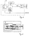
- Fig. 2 shows an embodiment of an inventive Device with video signal processing.
- One Microprocessor or a microcontroller ⁇ P serves as central control unit.
- a RS 232 interface - if necessary, a FIFO or a dual-ported RAM - is the microprocessor ⁇ P with an interface module (SCB module) connected according to the selected Bus, so formed, for example, a CAN bus is, and that has elements for bus control and - Communication and, where appropriate, elements for galvanic isolation, as optocoupler features.
- SCB module interface module
- the microprocessor ⁇ P controls on the one hand a video signal processor (Video Signal Processing) to which the camera signal on the other hand receives from the Video signal processor, for example, stores data and / or over the bus in a patient file a computer stores.
- a video signal processor Video Signal Processing
- the video signal processor controls a graphics processor (Graphics Processor, Title Generator), the et al a video overlay that is user-configurable is to generate on a monitor, not shown can.
- graphics processor Graphics Processor, Title Generator
- the output signals of the video signal processor and the Graphic processors are superimposed as a video output signal regardless of the bus output and, for example shown on an analogue or digital monitor and / or stored on a computer.
- Fig. 3 shows an implementation of the invention Security concept.
- a control computer for example under Windows NT
- the bus master control program is via a FIFO or a dual ported RAM with an interface card (CAN card) connected.
- CAN card interface card
- a so-called security task is provided the cyclic messages between the control computer and the interface card exchanges. Will in the Security task found that the data communication is disturbed, an alarm is issued. For this is the Interface card with an acoustic alarm Mistake. Otherwise, reference is made to the structure of FIG. 3.
- bus master automatically configures the bus and Can monitor if communication on the bus is correct expires.
Landscapes
- Physics & Mathematics (AREA)
- General Physics & Mathematics (AREA)
- Engineering & Computer Science (AREA)
- Automation & Control Theory (AREA)
- Endoscopes (AREA)
- Testing And Monitoring For Control Systems (AREA)
- User Interface Of Digital Computer (AREA)
Description
- Videosignal-Verarbeitungseinheit
- Steuerrechner
- Fernbedienungseinheit
- Netzwerk-Modul.
- Netzwerk-Modul.
- eine Insufflations- und eine Absaug-Einrichtung
- eine Lichtquelle und eine Videokamera, und /oder
- eine Druckmeßeinheit und eine Pumpe bzw. ein Insufflator
- Fig. 1a-d
- verschiedene Netzwerk-Konfigurationen,
- Fig. 2
- eine erfindungsgemäße Einrichtung mit Video-Signalverarbeitung, und
- Fig. 3
- eine Realisierung des erfindungsgemäßen Sicherheitskonzepts.
Claims (55)
- Einrichtung zur zentralen Überwachung und Steuerung wenigstens eines Gerätes für die Endoskopie, bei der das oder die zu steuernden Geräte über Bus-Schnittstellen miteinander verbunden sind, wobei in der Einrichtungdadurch gekennzeichnet, dass die Stromversorgung der Bus-Schnittstelle über die Busleitung erfolgt, wobei die Buskommunikation nicht unterbrochen wird, wenn ein am Bus angeschlossenes Gerät ausgeschaltet wird oder nicht eingeschaltet ist.die Geräte über die Bus-Schnittstellen an einen selbstkonfigurierenden Bus mit einem Bus-Master angeschlossen sind,der Bus-Master den Bus automatisch konfiguriert,der Bus-Master überwacht, ob die Kommunikation auf dem Bus korrekt abläuft,
- Einrichtung nach Anspruch 1, die für die minimal-invasive Chirurgie und zur Überwachung oder Steuerung einer Insufflationsvorrichtung, einer Pumpe, einer Lichtquelle und/oder einer Videokamera ausgebildet ist.
- Einrichtung nach Anspruch 1 oder 2,
dadurch gekennzeichnet, daß der selbstkonfigurierende Bus ein CAN-Bus ist. - Einrichtung nach einem der Ansprüche 1 bis 3,
dadurch gekennzeichnet, daß die BUS-Arbitrierung sowie die Datenübertragung über eine Zweidrahtleitung erfolgt. - Einrichtung nach einem der Ansprüche 1 bis 4,
dadurch gekennzeichnet, daß die Busverbindung zumindest zwischen einem Teil der Geräte über eine Infrarot- oder Funk-Übertragungsstrecke erfolgt. - Einrichtung nach einem der Ansprüche 1 bis 5,
dadurch gekennzeichnet, daß der Bus selbsttätig terminiert wird. - Einrichtung nach einem der Ansprüche 1 bis 6,
dadurch gekennzeichnet, daß die Stromversorgung der Schnittstelle über die Busleitung mittels nicht zur Kommunikation benötigter Leitungen erfolgt. - Einrichtung nach einem der Ansprüche 1 bis 7,
dadurch gekennzeichnet, daß die Schnittstelle vom jeweiligen Gerät galvanisch getrennt ist. - Einrichtung nach einem der Ansprüche 1 bis 8,
dadurch gekennzeichnet, daß eines der an den Bus angeschlossenen Geräte eine Fernbedienung für wenigstens ein weiteres Gerät ist. - Einrichtung nach Anspruch 9,
dadurch gekennzeichnet, daß die Fernbedienung mehr als ein Gerät steuern kann, und sich selbsttätig auf das jeweils zu steuernde Gerät konfiguriert. - Einrichtung nach Anspruch 9 oder 10,
dadurch gekennzeichnet, daß die Fernbedienung derart aufgebaut ist, daß sie im Sterilbereich einsetzbar ist. - Einrichtung nach einem der Ansprüche 9 bis 11,
Dadurch gekennzeichnet, daß die über die Fernsteuerung getätigten Änderungen der Einstellung von Geräten graphisch angezeigt werden. - Einrichtung nach einem der Ansprüche 1 bis 12,
dadurch gekennzeichnet, daß mindestens eines der folgenden Geräte als BUS-Master konfiguriert ist:Videosignal-VerarbeitungseinheitSteuerrechnerFernbedienungseinheitNetzwerk-Modul. - Einrichtung nach Anspruch 13,
dadurch gekennzeichnet, daß das Netzwerk-Modul an jedes an den Bus anschließbare Gerät anschließbar und andockbar ist. - Einrichtung nach einem der Ansprüche 1 bis 14,
dadurch gekennzeichnet, daß dann, wenn mehr als ein als BUS-Master verwendbares Gerät an den Bus angeschlossen ist, durch eine Arbitrierung sichergestellt ist, daß nur ein BUS-Master aktiv die BUS-Master-Funktion übernimmt. - Einrichtung nach einem der Ansprüche 1 bis 15,
dadurch gekennzeichnet, daß der BUS-Master ein Steuerrechner und ein Industriestandard-PC mit einer Bus-Schnittstelle ist. - Einrichtung nach Anspruch 16,
dadurch gekennzeichnet, daß der Steuerrechner in einem Programmierungs- und in einem Anwendungs-bzw. Kommunikationsmodus arbeitet. - Einrichtung nach Anspruch 16,
dadurch gekennzeichnet, daß im Programmierungsmodus die Betriebsparameter der zu steuernden Geräte voreingestellt und als Voreinstellung abgespeichert werden können, und
daß im Anwendungsmodus die Betriebsparameter nur aktuell ohne Beeinflussung der Grundeinstellung abgeändert werden können. - Einrichtung nach Anspruch 18,
dadurch gekennzeichnet, daß für jedes zu steuernde Gerät mehrere unterschiedliche Voreinstellungen abgespeichert werden können, die von der Bedienungsperson entsprechend der jeweiligen Situation abgerufen werden können. - Einrichtung nach Anspruch 18 oder 19,
dadurch gekennzeichnet, daß im Programmierungsmodus die Durchführung eines Behandlungsvorganges nicht möglich ist. - Einrichtung nach einem der Ansprüche 16 bis 20,
dadurch gekennzeichnet, daß der Steuerrechner eine graphische Benutzeroberfläche hat. - Einrichtung nach Anspruch 21,
dadurch gekennzeichnet, daß die auf einem Bildschirm des Steuerrechners dargestellte Benutzeroberfläche von der Bedienungsperson konfigurierbar ist. - Einrichtung nach Anspruch 20 oder 21,
dadurch gekennzeichnet, daß auf dem Bildschirm, auf dem die Benutzeroberfläche dargestellt ist, die Bedienelemente wenigstens eines herkömmlichen Geräts, wie Ein-/Aus-Schalter, Schiebe- oder Drehknöpfe sowie sonstige Funktionstasten graphisch nachgebildet sind. - Einrichtung nach Anspruch 23,
dadurch gekennzeichnet, daß auf dem Bildschirm die Bedienelemente mehrerer Geräte gleichzeitig dargestellt sind. - Einrichtung nach Anspruch 23 oder 24,
dadurch gekennzeichnet, daß lediglich eine von der Bedienungsperson konfigurierbare Auswahl von Bedienelementen des oder der Geräte gleichzeitig dargestellt ist. - Einrichtung nach Anspruch 29,
dadurch gekennzeichnet, daß entsprechend der jeweils abgerufenen Voreinstellung lediglich bestimmte Parameter der an den Bus angeschlossenen Geräte verändert werden können. - Einrichtung nach einem der Ansprüche 16 bis 26,
dadurch gekennzeichnet, daß die Bedienung des Steuerrechners mittels einer Maus, eines Joy-Sticks, einer Rollkugel erfolgt. - Einrichtung nach einem der Ansprüche 16 bis 26,
dadurch gekennzeichnet, daß die Bedienung des Steuerrechners mittels eines Touch-Screens erfolgt. - Einrichtung nach Anspruch 27 oder 28,
dadurch gekennzeichnet, daß die Bedienelemente derart ausgebildet sind, daß eine Bedienung im Sterilbereich möglich ist - Einrichtung nach einem der Ansprüche 1 bis 29,
dadurch gekennzeichnet, daß die über den Bus steuerbaren Funktionen durch ein Spracheingabe- und Verarbeitungsmodul sprachgesteuert werden. - Einrichtung nach Anspruch 30,
dadurch gekennzeichnet, daß die Sprachkommandos auf einem Bildschirm graphisch angezeigt oder akustisch bestätigt werden. - Einrichtung nach Anspruch 31,
dadurch gekennzeichnet, daß fehlerhaft eingegebene Kommandos bzw. Steuervorgänge unmittelbar rückgängig gemacht werden können. - Einrichtung nach einem der Ansprüche 1 bis 32
dadurch gekennzeichnet, daß eine Videosignal-Verarbeitungseinheit vorhanden ist, an der das Bildsignal einer Videokamera angelegt ist. - Einrichtung nach Anspruch 33,
dadurch gekennzeichnet, daß die Videokamera eine analoge oder digitale Videokamera ist. - Einrichtung nach Anspruch 33 oder 34,
dadurch gekennzeichnet, daß die Videosignal-Verarbeitungseinheit eine Bildverarbeitungseinheit aufweist. - Einrichtung nach einem der Ansprüche 33 bis 35,
dadurch gekennzeichnet, daß die Videosignal-Verarbeitungseinheit das von der Videokamera aufgenommene Bild digitalisiert und in einem Fenster der graphischen Benutzeroberfläche des Steuerrechners darstellt. - Einrichtung nach einem der Ansprüche 33 bis 36,
dadurch gekennzeichnet, daß die Videossignal-Verarbeitungseinheit das von der Videokamera aufgenommene Bild digitalisiert und in einem Steuerrechner ablegt, in dem auch Patientenstammdaten sowie Geräteparameter in Zuordnung zu den gespeicherten Bildern gespeichert werden können. - Einrichtung nach einem der Ansprüche 33 bis 37,
dadurch gekennzeichnet, daß die Videosignal-Verarbeitungseinheit das von der Videokamera aufgenommene Bild auf einem Analog-Monitor oder dem Monitor des Steuerrechners darstellt. - Einrichtung nach einem der Ansprüche 33 bis 38,
dadurch gekennzeichnet, daß die Videosignal-Verarbeitungseinheit die über den Bus empfangenen Informationen in einem Video-Overlay auf dem Analog-Monitor darstellt. - Einrichtung nach Anspruch 39,
dadurch gekennzeichnet, daß das Video-Overlay vom Anwender konfigurierbar ist. - Einrichtungen nach Anspruch 40,
dadurch gekennzeichnet, daß das Video-Overlay Geräte- und/oder Behandlungsparameter und/oder Fehlermeldungen anzeigt. - Einrichtung nach einem der Ansprüche 33 bis 41,
dadurch gekennzeichnet, daß die Videosignal-Verarbeitungseinheit einen Mikroprozessor aufweist, der die Videosignalverarbeitung sowie gegebenenfalls eine Graphikprozessor steuert, der Daten und/oder das Overlay-Bild in das aktuell aufgenommene Videobild einblendet. - Einrichtung nach einem der Ansprüche 1 bis 42,
dadurch gekennzeichnet, daß die über die Fernsteuerung getätigten Einstellungsänderung auf dem Bildschirm des Steuerrechners oder mittels eines Video-Overlays graphisch angezeigt werden. - Einrichtung nach einem der Ansprüche 1 bis 43,
dadurch gekennzeichnet, daß die Videokamera und der Videomonitor direkt und nicht über den Bus an der Videosignal-Verarbeitungseinheit angeschlossen sind. - Einrichtung nach einem der Ansprüche 1 bis 44,
dadurch gekennzeichnet, daß mindestens zwei Geräte über den Bus zu einem geschlossenen Regelkreis verbunden sind. - Einrichtung nach Anspruch 45,
dadurch gekennzeichnet, daß der über den Bus vermittelte Regelkreis Geräte-interne Regelungen überlagert. - Einrichtung nach Anspruch 46,
dadurch gekennzeichnet, daß der über den Bus vermittelte Regelkreis eine wesentlich langsamere Zeitkonstante als die Geräte-interne Regelung hat. - Einrichtung nach einem der Ansprüche 45 bis 47,
dadurch gekennzeichnet, daß die über den Bus zu einem geschlossenen Regelkreis verbundenen Geräteeine Insufflations- und eine Absaug-Einrichtungeine Lichtquelle und eine Videokamera, und /odereine Druckmeßeinheit und eine Pumpe bzw. ein Insufflator sind. - Einrichtung nach einem der Ansprüche 1 bis 48,
dadurch gekennzeichnet, daß die Bus-Karte über eine serielle Schnittstelle, ein FIFO oder ein Dual Ported RAM mit dem Steuerrechner Daten austauscht. - Einrichtung nach Anspruch 49,
dadurch gekennzeichnet, daß eine Überwachungsfunktion vorgesehen ist, die bei einem Ausfall des Steuerrechners oder der Bus-Karte einen Alarm auslöst. - Einrichtung nach einem der Ansprüche 1 bis 50,
dadurch gekennzeichnet, daß die Software so gestaltet ist, daß ein Ausfall der Software oder der Hardware dem Anwender sicher angezeigt wird, so daß ein Standard-Betriebssystem und Standard Hardware ohne Sicherheitseinbussen eingesetzt werden können. - Einrichtung nach einem der Ansprüche 1 bis 51,
dadurch gekennzeichnet, daß die Software so gestaltet ist, das Benutzer der Einrichtung eindeutig identifizierbar ist. - Einrichtung nach Anspruch 52,
dadurch gekennzeichnet, daß die Eingabe des jeweiligen Benutzers die Grundeinstellung der Einrichtung ändert. - Einrichtung nach einem der Ansprüche 1 bis 53,
dadurch gekennzeichnet, daß die Software so gestaltet ist, daß jedes an Bus angeschlossene Gerät individuell konfiguriert werden kann. - Einrichtung nach einem der Ansprüche 1 bis 54,
dadurch gekennzeichnet, daß die Software so gestaltet ist, daß die für einen bestimmten Vorgang benötigte Voreinstellung der am Bus angeschlossenen Geräte gespeichert werden kann.
Applications Claiming Priority (5)
| Application Number | Priority Date | Filing Date | Title |
|---|---|---|---|
| DE19710191 | 1997-03-12 | ||
| DE19710191 | 1997-03-13 | ||
| DE19733005 | 1997-07-22 | ||
| DE19733005A DE19733005B4 (de) | 1997-03-12 | 1997-07-22 | Einrichtung zur zentralen Überwachung und/oder Steuerung wenigstens eines Gerätes |
| PCT/EP1998/001445 WO1998040822A1 (de) | 1997-03-12 | 1998-03-12 | Einrichtung zur zentralen überwachung und/oder steuerung wenigstens eines gerätes |
Publications (2)
| Publication Number | Publication Date |
|---|---|
| EP1034480A1 EP1034480A1 (de) | 2000-09-13 |
| EP1034480B1 true EP1034480B1 (de) | 2005-12-07 |
Family
ID=26034773
Family Applications (1)
| Application Number | Title | Priority Date | Filing Date |
|---|---|---|---|
| EP98916931A Expired - Lifetime EP1034480B1 (de) | 1997-03-12 | 1998-03-12 | Einrichtung zur zentralen überwachung und/oder steuerung wenigstens eines gerätes |
Country Status (4)
| Country | Link |
|---|---|
| US (1) | US6397286B1 (de) |
| EP (1) | EP1034480B1 (de) |
| DE (2) | DE19733005B4 (de) |
| WO (1) | WO1998040822A1 (de) |
Cited By (2)
| Publication number | Priority date | Publication date | Assignee | Title |
|---|---|---|---|---|
| EP1995679A1 (de) | 2007-05-25 | 2008-11-26 | Karl Storz GmbH & Co. KG | Vorrichtung und Verfahren zur zentralen Überwachung und/oder Steuerung wenigstens eines Gerätes |
| EP2063374A1 (de) | 2007-11-13 | 2009-05-27 | how to organize GmbH | Verfahren und Vorrichtung zur Dokumentation medizinischer Daten |
Families Citing this family (52)
| Publication number | Priority date | Publication date | Assignee | Title |
|---|---|---|---|---|
| DE19904090C2 (de) * | 1999-02-02 | 2003-06-05 | Wolf Gmbh Richard | Verfahren und Vorrichtung zur automatischen Steuerung und Verwaltung medizinischer Geräte und Anlagen |
| US6484221B1 (en) * | 1999-10-01 | 2002-11-19 | Storz Endoskop Gmbh | Bus extension for multiple masters |
| AU2744701A (en) | 1999-12-29 | 2001-07-09 | Hill-Rom Services, Inc. | Hospital bed |
| DE10007266A1 (de) * | 2000-02-17 | 2001-09-13 | Vtq Videotronik Gmbh | Komplexes bidirektionales Kontroll- und Überwachungssystem |
| US6760772B2 (en) | 2000-12-15 | 2004-07-06 | Qualcomm, Inc. | Generating and implementing a communication protocol and interface for high data rate signal transfer |
| US6981086B2 (en) * | 2000-12-21 | 2005-12-27 | National Instruments Corporation | Instrumentation system including a backplane having a switched fabric bus and instrumentation lines |
| DE10126749A1 (de) * | 2001-05-31 | 2003-01-23 | Wittenstein Ag | Datenverarbeitungsstruktur |
| US8812706B1 (en) | 2001-09-06 | 2014-08-19 | Qualcomm Incorporated | Method and apparatus for compensating for mismatched delays in signals of a mobile display interface (MDDI) system |
| US6824539B2 (en) | 2002-08-02 | 2004-11-30 | Storz Endoskop Produktions Gmbh | Touchscreen controlling medical equipment from multiple manufacturers |
| US7252633B2 (en) * | 2002-10-18 | 2007-08-07 | Olympus Corporation | Remote controllable endoscope system |
| US8328793B2 (en) * | 2002-12-13 | 2012-12-11 | Brainlab Ag | Device, system and method for integrating different medically applicable apparatuses |
| US7844657B2 (en) * | 2003-01-17 | 2010-11-30 | Storz Endoskop Produktions Gmbh | System for controlling medical devices |
| CN105406947A (zh) | 2003-06-02 | 2016-03-16 | 高通股份有限公司 | 生成并实施一用于更高数据率的讯号协议和接口 |
| EP1661351A2 (de) | 2003-08-13 | 2006-05-31 | Qualcomm, Incorporated | Signalschnittstelle für höhere datenraten |
| CN1879383A (zh) | 2003-09-10 | 2006-12-13 | 高通股份有限公司 | 高数据速率接口 |
| CN102801615A (zh) | 2003-10-15 | 2012-11-28 | 高通股份有限公司 | 高数据速率接口 |
| WO2005043862A1 (en) | 2003-10-29 | 2005-05-12 | Qualcomm Incorporated | High data rate interface |
| CN101729205A (zh) | 2003-11-12 | 2010-06-09 | 高通股份有限公司 | 具有改进链路控制的高数据速率接口 |
| KR20060096161A (ko) | 2003-11-25 | 2006-09-07 | 콸콤 인코포레이티드 | 향상된 링크 동기화를 제공하는 고속 데이터 레이트인터페이스 |
| CN102497368A (zh) | 2003-12-08 | 2012-06-13 | 高通股份有限公司 | 具有改进链路同步的高数据速率接口 |
| JP2007528681A (ja) | 2004-03-10 | 2007-10-11 | クゥアルコム・インコーポレイテッド | 高データレートインタフェース装置及び方法 |
| EP1735986B1 (de) | 2004-03-17 | 2013-05-22 | Qualcomm, Incorporated | Schnittstellenvorrichtung und-verfahren für hohe datenraten |
| AU2005227500B2 (en) | 2004-03-24 | 2008-12-04 | Qualcomm Incorporated | High data rate interface apparatus and method |
| CN1993948A (zh) | 2004-06-04 | 2007-07-04 | 高通股份有限公司 | 高数据速率接口设备和方法 |
| US8650304B2 (en) | 2004-06-04 | 2014-02-11 | Qualcomm Incorporated | Determining a pre skew and post skew calibration data rate in a mobile display digital interface (MDDI) communication system |
| US7861334B2 (en) | 2005-12-19 | 2011-01-04 | Stryker Corporation | Hospital bed |
| US9038217B2 (en) | 2005-12-19 | 2015-05-26 | Stryker Corporation | Patient support with improved control |
| CN101103569B (zh) * | 2004-11-24 | 2012-05-23 | 高通股份有限公司 | 用于传递数据的数字数据接口装置和方法 |
| US8873584B2 (en) | 2004-11-24 | 2014-10-28 | Qualcomm Incorporated | Digital data interface device |
| US8667363B2 (en) * | 2004-11-24 | 2014-03-04 | Qualcomm Incorporated | Systems and methods for implementing cyclic redundancy checks |
| US20060161691A1 (en) * | 2004-11-24 | 2006-07-20 | Behnam Katibian | Methods and systems for synchronous execution of commands across a communication link |
| US8699330B2 (en) | 2004-11-24 | 2014-04-15 | Qualcomm Incorporated | Systems and methods for digital data transmission rate control |
| US8723705B2 (en) * | 2004-11-24 | 2014-05-13 | Qualcomm Incorporated | Low output skew double data rate serial encoder |
| US8692838B2 (en) * | 2004-11-24 | 2014-04-08 | Qualcomm Incorporated | Methods and systems for updating a buffer |
| US8539119B2 (en) * | 2004-11-24 | 2013-09-17 | Qualcomm Incorporated | Methods and apparatus for exchanging messages having a digital data interface device message format |
| US7315265B2 (en) * | 2004-11-24 | 2008-01-01 | Qualcomm Incorporated | Double data rate serial encoder |
| US20060224766A1 (en) * | 2005-03-31 | 2006-10-05 | Malackowski Donald W | Operating room communication bus and method |
| JP4727302B2 (ja) | 2005-06-02 | 2011-07-20 | 富士フイルム株式会社 | 超音波内視鏡システムおよび電子内視鏡システム |
| DE102005054843A1 (de) * | 2005-11-15 | 2007-05-16 | Dewert Antriebs Systemtech | Verfahren zur Steuerung einer Elektrogeräteanordnung, insbesondere für ein Möbel |
| US8730069B2 (en) | 2005-11-23 | 2014-05-20 | Qualcomm Incorporated | Double data rate serial encoder |
| US8692839B2 (en) | 2005-11-23 | 2014-04-08 | Qualcomm Incorporated | Methods and systems for updating a buffer |
| US11246776B2 (en) | 2005-12-19 | 2022-02-15 | Stryker Corporation | Patient support with improved control |
| US7881430B2 (en) * | 2006-07-28 | 2011-02-01 | General Electric Company | Automatic bus management |
| CA2662869A1 (en) * | 2006-09-07 | 2008-03-13 | Advanced Medical Optics, Inc. | Systems and methods for historical display of surgical operating parameters |
| US8982195B2 (en) * | 2006-09-07 | 2015-03-17 | Abbott Medical Optics Inc. | Digital video capture system and method with customizable graphical overlay |
| US8633975B2 (en) * | 2008-01-16 | 2014-01-21 | Karl Storz Imaging, Inc. | Network based endoscopic surgical system |
| US10806351B2 (en) * | 2009-09-15 | 2020-10-20 | Sotera Wireless, Inc. | Body-worn vital sign monitor |
| SE538207C2 (sv) * | 2009-09-23 | 2016-04-05 | Abb Technology Ltd | Säkerhetsarrangemang |
| US9060674B2 (en) | 2012-10-11 | 2015-06-23 | Karl Storz Imaging, Inc. | Auto zoom for video camera |
| FR3037432B1 (fr) * | 2015-06-09 | 2020-10-09 | Innovative Tech | Systeme de comptage et de guidage a la place utilise dans les parkings utilisant la technologies bus can, selon la norme de bus can iso 11898-1, et proposant une amelioration de celle-ci |
| US11672934B2 (en) | 2020-05-12 | 2023-06-13 | Covidien Lp | Remote ventilator adjustment |
| US12647298B2 (en) * | 2023-07-31 | 2026-06-02 | Hill-Rom Services, Inc. | CAN bus interconnection circuit |
Family Cites Families (13)
| Publication number | Priority date | Publication date | Assignee | Title |
|---|---|---|---|---|
| US4688168A (en) | 1984-08-23 | 1987-08-18 | Picker International Inc. | High speed data transfer method and apparatus |
| US4870704A (en) | 1984-10-31 | 1989-09-26 | Flexible Computer Corporation | Multicomputer digital processing system |
| JPS6246182A (ja) | 1985-08-23 | 1987-02-28 | 井関農機株式会社 | 穀粒乾燥機 |
| US4774568A (en) * | 1986-01-27 | 1988-09-27 | Kabushiki Kaisha Toshiba | Endoscopic apparatus |
| DE3741833C1 (de) * | 1987-12-10 | 1989-04-20 | Wolf Gmbh Richard | Einrichtung zum UEberwachen der Betriebszustaende von Versorgungsgeraeten von Endoskopen |
| US4885538A (en) * | 1988-08-19 | 1989-12-05 | The Regents Of The University Of California | Low data rate low noise serial digital communication link for magnetic resonance imaging systems |
| US5309569A (en) * | 1992-04-24 | 1994-05-03 | Digital Equipment Corporation | Self-configuring bus termination component |
| DE4214426A1 (de) * | 1992-04-30 | 1993-11-04 | Rodenstock Instr | Einrichtung zur untersuchung bzw. behandlung der augen |
| DE9218373U1 (de) * | 1992-12-14 | 1994-01-27 | Dornier Medizintechnik GmbH, 81663 München | Arbeitsplatz für die minimal invasive Chirurgie |
| CA2159597C (en) * | 1993-03-31 | 2005-05-17 | Philip J. Branson | Managing information in an endoscopy system |
| FR2716286A1 (fr) | 1994-02-16 | 1995-08-18 | Debiotech Sa | Installation de surveillance à distance d'équipements commandables. |
| DE19501581C2 (de) * | 1995-01-20 | 1998-08-27 | Huettinger Medtech Gmbh | Bedienungseinrichtung für medizinisch-technische Systemarbeitsplätze |
| US6224542B1 (en) * | 1999-01-04 | 2001-05-01 | Stryker Corporation | Endoscopic camera system with non-mechanical zoom |
-
1997
- 1997-07-22 DE DE19733005A patent/DE19733005B4/de not_active Expired - Lifetime
-
1998
- 1998-03-12 WO PCT/EP1998/001445 patent/WO1998040822A1/de not_active Ceased
- 1998-03-12 EP EP98916931A patent/EP1034480B1/de not_active Expired - Lifetime
- 1998-03-12 US US09/180,692 patent/US6397286B1/en not_active Expired - Lifetime
- 1998-03-12 DE DE59813269T patent/DE59813269D1/de not_active Expired - Lifetime
Cited By (5)
| Publication number | Priority date | Publication date | Assignee | Title |
|---|---|---|---|---|
| EP1995679A1 (de) | 2007-05-25 | 2008-11-26 | Karl Storz GmbH & Co. KG | Vorrichtung und Verfahren zur zentralen Überwachung und/oder Steuerung wenigstens eines Gerätes |
| US9934359B2 (en) | 2007-05-25 | 2018-04-03 | Karl Storz Se & Co. Kg | Device and method for the central control of devices used during an operation |
| EP2063374A1 (de) | 2007-11-13 | 2009-05-27 | how to organize GmbH | Verfahren und Vorrichtung zur Dokumentation medizinischer Daten |
| EP2063371A1 (de) | 2007-11-13 | 2009-05-27 | how to organize GmbH | Vorrichtung und Verfahren zur Dokumentation medizinischer Daten |
| US10114928B2 (en) | 2007-11-13 | 2018-10-30 | Karl Storz Se & Co. Kg | Method and device for documenting medical data |
Also Published As
| Publication number | Publication date |
|---|---|
| EP1034480A1 (de) | 2000-09-13 |
| DE19733005A1 (de) | 1998-09-24 |
| DE59813269D1 (de) | 2006-01-12 |
| DE19733005B4 (de) | 2007-06-21 |
| US6397286B1 (en) | 2002-05-28 |
| WO1998040822A1 (de) | 1998-09-17 |
Similar Documents
| Publication | Publication Date | Title |
|---|---|---|
| DE19733005B4 (de) | Einrichtung zur zentralen Überwachung und/oder Steuerung wenigstens eines Gerätes | |
| EP1325458B1 (de) | System und verfahren zur zentralen steuerung von einrichtungen, die während einer operation benutzt werden | |
| EP1394717B1 (de) | Berührungsbildschirm zur Steuerung medizinischer Geräte mehrerer Hersteller | |
| EP1240418A1 (de) | Verfahren zur sicheren automatischen nachführung eines endoskops und verfolgung eines chirurgischen instrumentes | |
| WO2019020137A1 (de) | Medizintechnische vorrichtung zur speicherung und auswertung klinischer daten | |
| EP1995679A1 (de) | Vorrichtung und Verfahren zur zentralen Überwachung und/oder Steuerung wenigstens eines Gerätes | |
| EP2111177A1 (de) | Vorrichtung zur anzeige und verwaltung von systemparametern und daten eines zahnärztlichen behandlungsplatzes | |
| DE9218373U1 (de) | Arbeitsplatz für die minimal invasive Chirurgie | |
| EP4104189A1 (de) | Verfahren, vorrichtung und system zur fernüberwachung eines medizintechnischen geräts | |
| DE202018006356U1 (de) | Rollstuhl-Sondersteuerung | |
| DE102019208612B4 (de) | Verfahren zum Betrieb einer Magnetresonanzeinrichtung mit einer Patientenliege und Magnetresonanzeinrichtung | |
| DE102019118752B4 (de) | Verfahren zur adaptiven Funktionsneubelegung von Bedienelementen eines Bildaufnahmesystems sowie zugehöriges Bildaufnahmesystem | |
| WO2019020136A1 (de) | Vorrichtung und verfahren zur informationsverknüpfung und -auswertung von klinischen daten in einem medizinischen gerät | |
| DE102008043534B4 (de) | Zentrale Gerätesteuerung im Operationssaal | |
| EP1433432B1 (de) | System zum Integrieren verschiedener medizinisch verwendbarer Geräte | |
| DE102007031719B4 (de) | Kommunikationseinrichtung für ein chirurgisches System und chirurgisches System, insbesondere ophthalmisches mikrochirurgisches System zur Phako-Chirurgie | |
| DE102015003967A1 (de) | Modulares Beatmungssystem | |
| DE69625762T2 (de) | Steuer- und Wartungssystem für Dentaleinheit | |
| DE102007031718B4 (de) | Kommunikationseinrichtung für ein chirurgisches System und chirurgisches System, insbesondere ophtalmisches mikrochirurgisches System zur Phako-Chirurgie | |
| EP1671223A2 (de) | Eingabegerät zum aktivieren und steuern von funktionen mehrerer gerate eines zahnärztlichen oder dentalen behandlungs- oder arbeitsplatzes | |
| EP1671225A1 (de) | Schnittstellen-einheit für zahnä rztlichen oder dentalen behandlungs-/arbeitsplatz zur weiterleitung von bildinformationen enthaltenden signalen | |
| DE102008043531A1 (de) | Zentrales Netzwerk im Operationssaal | |
| EP4261862A1 (de) | Medizintechnisches gerät mit drahtlos angebundenem fussschalter | |
| DE102007031717B4 (de) | Kommunikationseinrichtung für eine chirurgisches System und chirurgisches System, inbesondere ophthalmisches mikrochirurgisches System zur Phako-Chirurgie | |
| DE102012008903A1 (de) | Ophthalmologische Vorrichtung |
Legal Events
| Date | Code | Title | Description |
|---|---|---|---|
| PUAI | Public reference made under article 153(3) epc to a published international application that has entered the european phase |
Free format text: ORIGINAL CODE: 0009012 |
|
| 17P | Request for examination filed |
Effective date: 19990304 |
|
| AK | Designated contracting states |
Kind code of ref document: A1 Designated state(s): DE FR GB IT |
|
| 17Q | First examination report despatched |
Effective date: 20040225 |
|
| APBN | Date of receipt of notice of appeal recorded |
Free format text: ORIGINAL CODE: EPIDOSNNOA2E |
|
| APBR | Date of receipt of statement of grounds of appeal recorded |
Free format text: ORIGINAL CODE: EPIDOSNNOA3E |
|
| APBV | Interlocutory revision of appeal recorded |
Free format text: ORIGINAL CODE: EPIDOSNIRAPE |
|
| GRAP | Despatch of communication of intention to grant a patent |
Free format text: ORIGINAL CODE: EPIDOSNIGR1 |
|
| GRAS | Grant fee paid |
Free format text: ORIGINAL CODE: EPIDOSNIGR3 |
|
| GRAA | (expected) grant |
Free format text: ORIGINAL CODE: 0009210 |
|
| AK | Designated contracting states |
Kind code of ref document: B1 Designated state(s): DE FR GB IT |
|
| REG | Reference to a national code |
Ref country code: GB Ref legal event code: FG4D Free format text: NOT ENGLISH |
|
| GBT | Gb: translation of ep patent filed (gb section 77(6)(a)/1977) |
Effective date: 20051207 |
|
| REF | Corresponds to: |
Ref document number: 59813269 Country of ref document: DE Date of ref document: 20060112 Kind code of ref document: P |
|
| ET | Fr: translation filed | ||
| PLBE | No opposition filed within time limit |
Free format text: ORIGINAL CODE: 0009261 |
|
| STAA | Information on the status of an ep patent application or granted ep patent |
Free format text: STATUS: NO OPPOSITION FILED WITHIN TIME LIMIT |
|
| 26N | No opposition filed |
Effective date: 20060908 |
|
| REG | Reference to a national code |
Ref country code: FR Ref legal event code: PLFP Year of fee payment: 18 |
|
| REG | Reference to a national code |
Ref country code: FR Ref legal event code: PLFP Year of fee payment: 19 |
|
| REG | Reference to a national code |
Ref country code: FR Ref legal event code: PLFP Year of fee payment: 20 |
|
| PGFP | Annual fee paid to national office [announced via postgrant information from national office to epo] |
Ref country code: DE Payment date: 20170222 Year of fee payment: 20 Ref country code: FR Payment date: 20170221 Year of fee payment: 20 |
|
| PGFP | Annual fee paid to national office [announced via postgrant information from national office to epo] |
Ref country code: GB Payment date: 20170224 Year of fee payment: 20 |
|
| PGFP | Annual fee paid to national office [announced via postgrant information from national office to epo] |
Ref country code: IT Payment date: 20170221 Year of fee payment: 20 |
|
| REG | Reference to a national code |
Ref country code: DE Ref legal event code: R071 Ref document number: 59813269 Country of ref document: DE |
|
| REG | Reference to a national code |
Ref country code: GB Ref legal event code: PE20 Expiry date: 20180311 |
|
| PG25 | Lapsed in a contracting state [announced via postgrant information from national office to epo] |
Ref country code: GB Free format text: LAPSE BECAUSE OF EXPIRATION OF PROTECTION Effective date: 20180311 |