EP1036526B1 - Vorrichtung zur Stabilisierung des Laufverhaltens einer in einem M-belkorpus verfahrbaren Schublade - Google Patents
Vorrichtung zur Stabilisierung des Laufverhaltens einer in einem M-belkorpus verfahrbaren Schublade Download PDFInfo
- Publication number
- EP1036526B1 EP1036526B1 EP00104058A EP00104058A EP1036526B1 EP 1036526 B1 EP1036526 B1 EP 1036526B1 EP 00104058 A EP00104058 A EP 00104058A EP 00104058 A EP00104058 A EP 00104058A EP 1036526 B1 EP1036526 B1 EP 1036526B1
- Authority
- EP
- European Patent Office
- Prior art keywords
- rack
- drawer
- teeth
- tooth
- movable tooth
- Prior art date
- Legal status (The legal status is an assumption and is not a legal conclusion. Google has not performed a legal analysis and makes no representation as to the accuracy of the status listed.)
- Expired - Lifetime
Links
- 230000003019 stabilising effect Effects 0.000 title 1
- 239000000463 material Substances 0.000 claims description 4
- 230000006641 stabilisation Effects 0.000 claims description 4
- 238000006073 displacement reaction Methods 0.000 claims description 2
- 230000013707 sensory perception of sound Effects 0.000 claims 2
- 238000011105 stabilization Methods 0.000 description 3
- 230000000087 stabilizing effect Effects 0.000 description 2
- 230000006835 compression Effects 0.000 description 1
- 238000007906 compression Methods 0.000 description 1
- 238000010586 diagram Methods 0.000 description 1
- 210000003128 head Anatomy 0.000 description 1
- 238000003780 insertion Methods 0.000 description 1
- 230000037431 insertion Effects 0.000 description 1
- 210000001331 nose Anatomy 0.000 description 1
- 238000005096 rolling process Methods 0.000 description 1
Images







Classifications
-
- A—HUMAN NECESSITIES
- A47—FURNITURE; DOMESTIC ARTICLES OR APPLIANCES; COFFEE MILLS; SPICE MILLS; SUCTION CLEANERS IN GENERAL
- A47B—TABLES; DESKS; OFFICE FURNITURE; CABINETS; DRAWERS; GENERAL DETAILS OF FURNITURE
- A47B88/00—Drawers for tables, cabinets or like furniture; Guides for drawers
- A47B88/40—Sliding drawers; Slides or guides therefor
- A47B88/44—Sequencing or synchronisation of drawer slides or functional units
- A47B88/45—Synchronisation of cooperating drawer slides, i.e. with a coordination of the rail movement of different drawer slides
-
- A—HUMAN NECESSITIES
- A47—FURNITURE; DOMESTIC ARTICLES OR APPLIANCES; COFFEE MILLS; SPICE MILLS; SUCTION CLEANERS IN GENERAL
- A47B—TABLES; DESKS; OFFICE FURNITURE; CABINETS; DRAWERS; GENERAL DETAILS OF FURNITURE
- A47B2210/00—General construction of drawers, guides and guide devices
- A47B2210/0002—Guide construction for drawers
- A47B2210/0064—Guide sequencing or synchronisation
- A47B2210/0078—Drawers with parallel guidance or synchronization by pinion-shaft linkages
Definitions
- the invention relates to a drawer with a device for stabilization the running behavior of the drawer, with the drawer in a furniture body is movable and has drawer frames, being on both sides of the drawer each a gear is provided which meshes with a respective body-side rack and the two gears, which are rotatably connected to each other, in bearing bodies Store, the height of the drawer relative to the drawer when moving the drawer are.
- a drawer with gears wherein in Furniture carcass racks are provided, which attach to the drawers run stored gears.
- the gears are on opposite sides of the Drawer arranged and connected to each other via a rod.
- the gears are mounted in brackets, which are designed such that the position of the Gears by means of a screw in height is adjustable.
- the object of the invention is to provide a device of the type mentioned above to improve that the hanging of the drawer is facilitated.
- Another object of the invention is to provide a good guidance of the gears on the To achieve racks.
- the object of the invention is achieved in that on the drawer Mounts are provided for the bearing body having guides, wherein the Bearing body directly in these guides relative to the drawer in height displaced are stored.
- At least one rack made of elastic compliant material, such as plastic is made and that the rearmost Mounting point of the rack on the furniture body so far in front of the rear end the rack is that the rack is deflectable in the correction area, wherein the rearmost attachment point of the rack on the furniture body in front of the Correction range is.
- a secure meshing of the gears with the To ensure racks is in one embodiment of the invention provided that in the bearing bodies horizontally and transversely to the direction of the Drawer slidable slide store in the traversing position of the drawer engage under horizontal guide rails of the racks.
- Another embodiment of the invention provides that on each rack at least one subsequent to the rear end of the row of teeth through the gear is provided relative to the rack movable tooth.
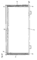
- a drawer 3 is by means of a conventional Auszieh Operationssgarnitur 4 between the side walls 1 of a furniture body movable.
- Auszieh Equipmentsgarnitur 4 may be both a single extension with a body-side mounting rail and a loading-side pull-out rail on both sides the drawer or to act a full statement, in which between the Body-side mounting rail and the loading-side pull-out rail a middle rail is stored.
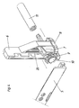
- the gears 10 store by means of their stub axles 27 in bearing bodies 7, which in turn are mounted vertically adjustable in brackets 6.
- the bearing body 7 are in the Holding bodies 6, for example, by means of a dovetail guide 26.
- the brackets 6 are on the drawer 3, preferably on the drawer 2 attached.
- the drawer 2 are with a rear provided angled web 28 on which the brackets 6 are pushed.
- the stub axles 27 of the gears 10 protrude through the bearing body 7 and in a sleeve-shaped rod 11, which at least in its two end regions with an internal toothing is provided. As a result, the two gears 10 to the both sides of the drawer 3 rotatably connected.
- a slider 9 is mounted below the gear 10, the is displaceable perpendicular to the direction of travel of the drawer 3.
- the slider 9 is acted upon by a spring 8 and pressed to the rack 5.
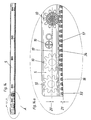
- Each rack is at its free edge with a horizontal guide rail 14th provided at the rear end of the rack 5 at a distance in front of a Guide block 29 ends.
- the guide block 29 is at its front end of a sloping guide 15 limited.
- Above the guide rail 14 is a vertical guide wall 30.
- the teeth 17, 18 are each arranged in a groove 31 of the rack 5 and are bounded by lateral guide walls.
- Each rack 5 is at its rear end with a correction area 24 provided in which the height of the teeth 18 is approximately half the height of the Teeth 17 in the remaining running area 25 of the rack.
- the height of the teeth 18 is at most 3/4 of the height of the teeth 17 and is preferably in a range between 2/3 and half the height of the teeth 17th
- the racks 5, which are made of a plastic material, are by means of Screwed screws 16 on the body side wall 1, wherein the rearmost screw 16, d. H. the rearmost attachment point of the rack 5 on the side wall 1 of the Furniture carcass is located at a distance a in front of the rear end of the rack 5.
- the gears are 10, as shown in Fig. 6, above the teeth 17, 18 of the racks 5 and the Noses of the slide 9 above the guide rails 14 of the racks 5.
- the Slide 9 abuts with its tip on the vertical guide wall 30 of the Rack 5 and is against the pressure of the spring 8 in the direction of Drawer center pressed.
- a stop 13 is provided to limit the slide path. So that the bearing body 7 is not too far up is pressed, the holders 6 stops 12, which the displacement of the Limit bearing body 7 vertically upwards.
- the drawer 3 is inserted so far into the furniture body until the slide 9 at the oblique guides 15 of the racks 5 abut. Due to the Slanted guides, the slide 9 are pressed down and snap below the Edge 32 of the blocks 29, wherein they from the springs 8 under the racks. 5 be pushed.
- the gear 10 rotates on the upper end surfaces of the teeth 18, wherein the rear end of the rack 5 pressed by the dimension 21 down and the axis of the gear 10 is pushed by the dimension 20 upwards.
- the Gear 10 can thus be rotated away over the teeth 18 until it in the rear end position in turn is brought into engagement with the teeth 18 (see FIG. 13a).
- the Tooth width 33 of the teeth 18 larger than the tooth head width 34 of the teeth 17th
- a movable tooth 18 is either As shown in FIGS. 17 to 22, mounted on an axis 23 tiltable or rotatable or, as shown in the embodiment of FIGS. 23 to 24, linearly displaceable.
- Fig. 25 shows a variant of the tiltable mounting, wherein the tooth 18 of the Gear 10 can escape laterally.
- the distance between the tooth 18 and the next rigid tooth 17 of the rack 5 in approximately twice as large as the distance between two adjacent rigid teeth 17.
- the movable tooth 18 only in one Dodge direction i. in the embodiment of FIGS. 17 to 24 can the tooth 18 only in the direction of the rearmost fixed tooth 17 of the rack 5 are moved.
- the lever 35, at the free end of the tooth 18 is formed, only in the direction of the arrow swing.
- the gear 10 on the left side can rotate until the gear 10th on the right side of the drawer 3 has reached the rearmost position. now is the Drawer 3 is straight and can be straight out of the furniture body be pulled out.
- the tiltably mounted on the axis 23 tooth 18 is vertically laterally with a side projecting arm 36 provided on which a spring 37 presses.
- the movable tooth 18 is on a slidable block 38 formed in a recess 42 of the rack. 5 is movable.
- the pad 38 is linearly displaceable in the direction of the rack 5 and is by a spring 37, this time a helical compression spring, to the rear pressed.
- the tooth 18 is on an arm 35 formed, which is rotatable about an axis 39.
- the tooth 18 is provided with a vertical inclined surface 40.
Landscapes
- Drawers Of Furniture (AREA)
Description
Claims (35)
- Schublade mit einer Vorrichtung zur Stabilisierung des Laufverhaltens der Schublade, wobei die Schublade in einem Möbelkorpus verfahrbar ist und Schubladenzargen aufweist, wobei an beiden Seiten der Schublade je ein Zahnrad vorgesehen ist, das jeweils mit einer korpusseitigen Zahnstange kämmt und die beiden Zahnräder, die drehfest miteinander verbunden sind, in Lagerkörpern lagern, die beim Lauf der Schublade relativ zu der Schublade in der Höhe verschiebbar sind, dadurch gekennzeichnet, daß an der Schublade Halterungen (6) für die Lagerkörper (7) vorgesehen sind, die Führungen aufweisen, wobei die Lagerkörper (7) direkt in diesen Führungen relativ zur Schublade in der Höhe verschiebbar gelagert sind.
- Vorrichtung nach Anspruch 1, dadurch gekennzeichnet, daß die Halterungen (6) Anschläge (12) aufweisen, die den Verschiebeweg der Lagerkörper (7) begrenzen.
- Vorrichtung nach Anspruch 1 oder 2, dadurch gekennzeichnet, daß in den Lagerkörpern (7) horizontal und quer zur Verfahrrichtung der Schublade (3) verschiebbare Schieber (9) lagern, die in der Verfahrstellung der Schublade (3) horizontale Führungsleisten (14) der Zahnstangen (4) untergreifen.
- Vorrichtung nach Anspruch 3, dadurch gekennzeichnet, daß Zahnstangen (5) oberhalb der Führungsleisten (14) vertikale Führungswände (30) aufweisen, an denen die Schieber (9) beim Einhängen der Schublade (3) anstoßen.
- Vorrichtung nach Anspruch 3 oder 4, dadurch gekennzeichnet, daß an den Zahnstangen (5) im hinteren Verfahrbereich der Schublade (3) Schrägführungen (15) für die Schieber (9) ausgebildet sind, durch die Schieber (9) vor einer oberhalb der Führungsleisten (14) befindlichen Position in eine unterhalb der Führungsleisten (14) befindliche Position geführt werden.
- Vorrichtung nach Anspruch 5, dadurch gekennzeichnet, daß die Schrägführungen (15) am Anfang der Korrekturbereiche (24) vorgesehen sind.
- Vorrichtung nach einem der Ansprüche 3 bis 6, dadurch gekennzeichnet, daß die Schieber (9) von einer Feder (8) beaufschlagt sind.
- Vorrichtung nach einem der Ansprüche 3 bis 6, dadurch gekennzeichnet, daß Lagerkörper (7) über Schwalbenschwanzführungen (26) an den Halterungen (6) geführt sind.
- Vorrichtung nach einem der Ansprüche 1 bis 8, dadurch gekennzeichnet, daß die Zahnräder (10) mit Steckachsen (27) versehen sind, die in eine Verbindungsstange (11) ragen, die zumindestens an ihren beiden Endbereichen hülsenförmig ausgeführt ist und dort eine Innenverzahnung aufweist.
- Vorrichtung nach einem der Ansprüche 1 bis 8, dadurch gekennzeichnet, daß die Zähne (17, 18) jeder Zahnstange (5) in einer Nut (31) mit seitlichen Führungsflanken für das Zahnrad (10) angeordnet sind.
- Vorrichtung nach Anspruch 1, dadurch gekennzeichnet, daß an jeder Zahnstange (5) mindestens ein an das hintere Ende der Zahnreihe anschließender durch das Zahnrad (10) relativ zur Zahnstange (5) bewegbarer Zahn (18) vorgesehen ist.
- Vorrichtung nach Anspruch 11, dadurch gekennzeichnet, daß der Abstand des bewegbaren Zahnes (18) vom hintersten festen Zahn (17) der Zahnstange (5) in etwa doppelt so groß ist wie der Abstand zwischen zwei benachbarten festen Zähnen (17) der Zahnstange (5).
- Vorrichtung nach Anspruch 11 oder 12, dadurch gekennzeichnet, daß der bewegbare Zahn (18) um eine horizontale Achse (23) kippbar ist.
- Vorrichtung nach Anspruch 13, dadurch gekennzeichnet, daß der bewegbare Zahn (18) auf einer Achse (23) lagert, die in der Zahnstange (5) verankert ist.
- Vorrichtung nach Anspruch 14, dadurch gekennzeichnet, daß der Zahn (18) auf der Achse (23) klemmend gehalten ist.
- Vorrichtung nach einem der Ansprüche 11 bis 15, dadurch gekennzeichnet, daß der bewegbare Zahn (18) von einer Feder (37) beaufschlagt wird, der ihn in die aufrechte Stellung drückt.
- Vorrichtung nach Anspruch 16, dadurch gekennzeichnet, daß der bewegbare Zahn (18) mit einem Arm (36) verbunden ist, an dem die Feder (37) angreift.
- Vorrichtung nach einem der Ansprüche 13 bis 17, dadurch gekennzeichnet, daß der bewegbare Zahn (18) nur in einer Richtung kippbar ist.
- Vorrichtung nach Anspruch 18, dadurch gekennzeichnet, daß der bewegbare Zahn (18) in der Richtung zu den festen Zähnen (17) der Zahnstange (5) kippbar ist.
- Vorrichtung nach Anspruch 11 oder 12, dadurch gekennzeichnet, daß der bewegbare Zahn (18) in der Längsrichtung der Zahnstange (5) linear verschiebbar ist.
- Vorrichtung nach Anspruch 20, dadurch gekennzeichnet, daß der verschiebbare Zahn (18) von einer Feder (37) zur Möbelrückwand gedrückt wird.
- Vorrichtung nach Anspruch 20 oder 21, dadurch gekennzeichnet, daß der linear verschiebbare Zahn (18) auf einem Klotz (38) angeordnet ist, der in eine Aussparung (42) am hinteren Ende der Zahnstange (5) eingesetzt ist.
- Vorrichtung nach einem der Ansprüche 20 bis 22, dadurch gekennzeichnet, daß der linear verschiebbare Zahn (18) durch das Zahnrad (10) nur in der Richtung zur Möbelfront bewegbar ist.
- Vorrichtung nach Anspruch 11 oder 12, dadurch gekennzeichnet, daß der bewegbare Zahn (18) eine vertikale Schägfläche (40) aufweist, über die der Zahn (18) vom Zahnrad (10) zur Seite, aus der Spur des Zahnrades (10) hinaus, drückbar ist.
- Vorrichtung nach Anspruch 1, dadurch gekennzeichnet, daß bei mindestens einer der Zahnstangen (5) ein an das hintere Ende der Zahnstangen (5) anschließender Korrekturbereich (24) vorgesehen ist, in dem die Höhe der Zähne geringer ist als die Höhe der Zähne (17) der restlichen Zahnstangen (5).
- Vorrichtung nach Anspruch 25, dadurch gekennzeichnet, daß die Höhe der Zähne (18) im Korrekturbereich (24) maximal 3/4, vorzugsweise maximal 2/3 der Höhe der restlichen Zähne (17) der Zahnstange (5) beträgt.
- Vorrichtung nach Anspruch 26, dadurch gekennzeichnet, daß die Höhe der Zähne (18) Korrekturbereich (24) zwischen 2/3 und der Hälfte der Höhe der Zähne (17) der restlichen Zahnstange (5) beträgt.
- Vorrichtung nach einem der Ansprüche 25 bis 27, dadurch gekennzeichnet, daß die Zahnkopfbreite (33) der Zähne (18) im Korrekturbereich (24) größer bemessen ist als die Zahnkopfbreite (34) der restlichen Zähne (17).
- Vorrichtung nach einem der Ansprüche 25 bis 28, dadurch gekennzeichnet, daß die mindestens eine Zahnstange (5) aus elastisch nachgiebigem Material, beispielsweise Kunststoff gefertigt ist und daß der hinterste Befestigungspunkt der Zahnstange (5) am Möbelkorpus so weit vor dem hinteren Ende der Zahnstange (5) liegt, daß die Zahnstange (5) im Korrekturbereich (24) durchbiegbar ist.
- Vorrichtung nach Anspruch 1, dadurch gekennzeichnet, daß die mindestens eine Zahnstange (5) aus elastisch nachgiebigem Material, beispielsweise Kunststoff gefertigt ist und daß der hinterste Befestigungspunkt der Zahnstange (5) am Möbelkorpus so weit vor dem hinteren Ende der Zahnstange (5) liegt, daß die Zahnstange (5) im Korrekturbereich (24) durchbiegbar ist.
- Vorrichtung nach Anspruch 29 oder 30, dadurch gekennzeichnet, daß der hinterste Befestigungspunkt der Zahnstange (5) am Möbelkorpus vor dem Korrekturbereich (24) liegt.
- Vorrichtung nach einem der Ansprüche 25 bis 31, dadurch gekennzeichnet, daß beide Zahnstangen (5) bei ihrem hinteren Ende mit einem Korrekturbereich (24) versehen sind.
- Vorrichtung nach Anspruch 9, dadurch gekennzeichnet, daß jede Steckachse (27) durch einen Lagerkörper (7) und eine Halterung (6) ragt.
- Vorrichtung nach einem der Ansprüche 1 bis 33, dadurch gekennzeichnet, daß die Halterungen (6) an den Schubladenzargen (2) befestigt sind.
- Vorrichtung nach Anspruch 34, dadurch gekennzeichnet, daß die Schubladenzargen (2) hinten abgewinkelte Stege (28) aufweisen, an denen die Halterungen (6) befestigt sind.
Priority Applications (1)
| Application Number | Priority Date | Filing Date | Title |
|---|---|---|---|
| EP05012879.2A EP1574151B1 (de) | 1999-03-17 | 2000-02-28 | Vorrichtung zur Stabilisierung des Laufverhaltens einer in einem Möbelkorpus verfahrbaren Schublade |
Applications Claiming Priority (4)
| Application Number | Priority Date | Filing Date | Title |
|---|---|---|---|
| AT47399 | 1999-03-17 | ||
| AT0047399A AT410162B (de) | 1999-03-17 | 1999-03-17 | Vorrichtung zur stabilisierung des laufverhaltens einer in einem möbelkorpus verfahrbaren schublade |
| AT152399 | 1999-09-06 | ||
| AT0152399A AT410163B (de) | 1999-09-06 | 1999-09-06 | Vorrichtung zur stabilisierung des laufverhaltens einer in einem möbelkorpus verfahrbaren schublade |
Related Child Applications (1)
| Application Number | Title | Priority Date | Filing Date |
|---|---|---|---|
| EP05012879.2A Division EP1574151B1 (de) | 1999-03-17 | 2000-02-28 | Vorrichtung zur Stabilisierung des Laufverhaltens einer in einem Möbelkorpus verfahrbaren Schublade |
Publications (2)
| Publication Number | Publication Date |
|---|---|
| EP1036526A1 EP1036526A1 (de) | 2000-09-20 |
| EP1036526B1 true EP1036526B1 (de) | 2005-08-24 |
Family
ID=25592852
Family Applications (2)
| Application Number | Title | Priority Date | Filing Date |
|---|---|---|---|
| EP05012879.2A Expired - Lifetime EP1574151B1 (de) | 1999-03-17 | 2000-02-28 | Vorrichtung zur Stabilisierung des Laufverhaltens einer in einem Möbelkorpus verfahrbaren Schublade |
| EP00104058A Expired - Lifetime EP1036526B1 (de) | 1999-03-17 | 2000-02-28 | Vorrichtung zur Stabilisierung des Laufverhaltens einer in einem M-belkorpus verfahrbaren Schublade |
Family Applications Before (1)
| Application Number | Title | Priority Date | Filing Date |
|---|---|---|---|
| EP05012879.2A Expired - Lifetime EP1574151B1 (de) | 1999-03-17 | 2000-02-28 | Vorrichtung zur Stabilisierung des Laufverhaltens einer in einem Möbelkorpus verfahrbaren Schublade |
Country Status (4)
| Country | Link |
|---|---|
| EP (2) | EP1574151B1 (de) |
| AT (2) | ATE302558T1 (de) |
| DE (1) | DE50011002D1 (de) |
| ES (2) | ES2445162T3 (de) |
Cited By (3)
| Publication number | Priority date | Publication date | Assignee | Title |
|---|---|---|---|---|
| WO2011075753A1 (de) | 2009-12-23 | 2011-06-30 | Julius Blum Gmbh | Schienensystem für schubladen |
| WO2011075752A1 (de) | 2009-12-23 | 2011-06-30 | Julius Blum Gmbh | Schienensystem für schubladen |
| WO2012159136A1 (de) | 2011-05-20 | 2012-11-29 | Julius Blum Gmbh | Synchronisationsvorrichtung für ein bewegbar gelagertes möbelteil |
Families Citing this family (25)
| Publication number | Priority date | Publication date | Assignee | Title |
|---|---|---|---|---|
| DE10228470A1 (de) | 2002-06-26 | 2004-01-15 | Grass Gmbh | Schubladenführung |
| DE202004016393U1 (de) * | 2004-10-21 | 2005-12-29 | Grass Gmbh | Vorrichtung zur Stabilisierung des Laufverhaltens eines in einem Möbelkorpus fahrbaren Möbelteiles |
| AT8111U1 (de) * | 2004-10-22 | 2006-02-15 | Fulterer Gmbh | Ausziehführung |
| DE202006000711U1 (de) * | 2006-01-18 | 2006-04-06 | Anton Schneider Gmbh & Co Kg | Differentialauszug für Schubladen o.dgl. |
| ES2318984B1 (es) * | 2006-08-04 | 2009-11-17 | Miguel Angel Rioja Calvo | Dispositivo para cajones de muebles. |
| KR100790543B1 (ko) * | 2006-10-25 | 2008-01-02 | 엘지전자 주식회사 | 바스켓출납용 레일어셈블리 |
| US7594707B2 (en) | 2007-08-15 | 2009-09-29 | Whirlpool Corporation | Snap-in bearing rack and pinion system |
| DE202008012077U1 (de) * | 2008-09-11 | 2010-02-25 | Paul Hettich Gmbh & Co. Kg | Synchronführung eines Schubelementes |
| TW201039777A (en) * | 2009-05-05 | 2010-11-16 | Zong-Yao Chen | Drawing stabilization structure of cupboard-drawing bearing member |
| DE202009016105U1 (de) * | 2009-07-06 | 2010-12-02 | Paul Hettich Gmbh & Co. Kg | Synchronführung eine Schubelements und Möbel |
| CN102090800B (zh) * | 2009-12-15 | 2015-04-08 | 陈崇尧 | 橱柜抽拉承载件的抽拉平稳结构 |
| CN101716032B (zh) * | 2009-12-17 | 2012-01-18 | 伍志勇 | 抽屉平衡机构 |
| TW201225884A (en) * | 2010-12-30 | 2012-07-01 | Chong-Yao Chen | Drawing synchronization device of side-travelling type slide rail and support unit and slide rail unit thereof |
| AT13201U1 (de) * | 2011-01-28 | 2013-08-15 | Blum Gmbh Julius | Möbelteil mit einer drehmomentübertragenden Welle |
| TW201320927A (zh) * | 2011-11-21 | 2013-06-01 | 陳崇堯 | 抽拉同步裝置及其軸裝單元 |
| AT512382B1 (de) | 2011-12-27 | 2016-05-15 | Blum Gmbh Julius | Synchronisationsvorrichtung für eine schublade |
| DE202012002127U1 (de) * | 2012-02-29 | 2013-06-06 | Grass Gmbh | Vorrichtung zur Stabilisierung des Laufverhaltens eines in einem Möbelkorpus verfahrbaren Möbelteils |
| KR20130115546A (ko) * | 2012-04-12 | 2013-10-22 | 삼성전자주식회사 | 슬라이딩 장치 및 이를 갖는 냉장고 |
| US20130270987A1 (en) * | 2012-04-17 | 2013-10-17 | Electrolux Home Products, Inc. | Freezer slide rack alignment |
| DE102012111977B4 (de) | 2012-12-07 | 2024-01-11 | Paul Hettich Gmbh & Co. Kg | Schubelement |
| CN103960890B (zh) * | 2014-05-14 | 2016-08-31 | 伍志勇 | 一种抽屉滑轨同步装置的辅助稳定机构 |
| TWI612231B (zh) * | 2017-03-20 | 2018-01-21 | 川湖科技股份有限公司 | 齒輪裝置 |
| CN108652284B (zh) * | 2017-03-28 | 2023-08-08 | 川湖科技股份有限公司 | 齿轮装置 |
| AT520817B1 (de) | 2018-02-01 | 2019-08-15 | Blum Gmbh Julius | Anordnung aus Ausziehführung, Schienen-Synchronisierungsvorrichtung und Mitnehmer |
| CN108741784A (zh) * | 2018-06-04 | 2018-11-06 | 安徽知之信息科技有限公司 | 一种用于杂物收纳的机器人 |
Citations (1)
| Publication number | Priority date | Publication date | Assignee | Title |
|---|---|---|---|---|
| DE8905197U1 (de) * | 1989-04-25 | 1989-06-08 | Paul Hettich GmbH & Co, 4983 Kirchlengern | Vorrichtung zur Gewährleistung des Parallellaufes eines Möbelauszuges |
Family Cites Families (13)
| Publication number | Priority date | Publication date | Assignee | Title |
|---|---|---|---|---|
| GB436082A (en) * | 1934-03-28 | 1935-09-30 | William Mackey Stavers | Improvements in rack and pinion mechanism |
| US2214291A (en) | 1937-10-13 | 1940-09-10 | Wyckoff William Le Roy | Cabinet |
| US2410643A (en) * | 1944-10-17 | 1946-11-05 | Fielding Charles Stuart | Rack and pinion mechanism |
| US2620253A (en) * | 1948-05-20 | 1952-12-02 | Robert C Read | Glide control means for drawers |
| US3323853A (en) * | 1965-12-06 | 1967-06-06 | Art Metal Inc | Filing cabinet drawer motion control means |
| DE2609977A1 (de) * | 1976-03-10 | 1977-09-15 | Siemens Ag | Einlaufzahnstange fuer angetriebene foerderwagen |
| US4226490A (en) | 1978-08-04 | 1980-10-07 | General Electric Company | Stabilizing arrangement for movably mounted drawer or rack |
| DD217293A1 (de) * | 1983-07-18 | 1985-01-09 | Groeditz Stahl Walzwerk Veb | Zahnstangentrieb |
| NL9100758A (nl) * | 1991-05-02 | 1992-12-01 | Regout Nv Thomas | Anti-schranksysteem voor een schuiflade. |
| US5409309A (en) | 1993-04-19 | 1995-04-25 | Whirlpool Corporation | Dishrack motion control arrangement for a dishwasher |
| GB9416305D0 (en) * | 1994-08-12 | 1994-10-05 | Alliedsignal Ltd | Driving arrangement |
| TR199501601A2 (tr) * | 1994-12-19 | 1996-07-21 | Bosch Siemens Hausgeraete | Sogutucu. |
| DE19718069C1 (de) | 1997-04-29 | 1998-05-28 | Schock Metallwerk | Parallelauszugführung |
-
2000
- 2000-02-28 DE DE50011002T patent/DE50011002D1/de not_active Expired - Lifetime
- 2000-02-28 ES ES05012879.2T patent/ES2445162T3/es not_active Expired - Lifetime
- 2000-02-28 ES ES00104058T patent/ES2244369T3/es not_active Expired - Lifetime
- 2000-02-28 EP EP05012879.2A patent/EP1574151B1/de not_active Expired - Lifetime
- 2000-02-28 AT AT00104058T patent/ATE302558T1/de active
- 2000-02-28 EP EP00104058A patent/EP1036526B1/de not_active Expired - Lifetime
-
2003
- 2003-11-03 AT AT0075703U patent/AT6674U3/de not_active IP Right Cessation
Patent Citations (1)
| Publication number | Priority date | Publication date | Assignee | Title |
|---|---|---|---|---|
| DE8905197U1 (de) * | 1989-04-25 | 1989-06-08 | Paul Hettich GmbH & Co, 4983 Kirchlengern | Vorrichtung zur Gewährleistung des Parallellaufes eines Möbelauszuges |
Cited By (6)
| Publication number | Priority date | Publication date | Assignee | Title |
|---|---|---|---|---|
| WO2011075753A1 (de) | 2009-12-23 | 2011-06-30 | Julius Blum Gmbh | Schienensystem für schubladen |
| WO2011075752A1 (de) | 2009-12-23 | 2011-06-30 | Julius Blum Gmbh | Schienensystem für schubladen |
| AT509257B1 (de) * | 2009-12-23 | 2013-09-15 | Blum Gmbh Julius | Schienensystem für schubladen |
| WO2012159136A1 (de) | 2011-05-20 | 2012-11-29 | Julius Blum Gmbh | Synchronisationsvorrichtung für ein bewegbar gelagertes möbelteil |
| AT511511A1 (de) * | 2011-05-20 | 2012-12-15 | Blum Gmbh Julius | Synchronisationsvorrichtung für ein bewegbar gelagertes möbelteil |
| AT511511B1 (de) * | 2011-05-20 | 2015-05-15 | Blum Gmbh Julius | Synchronisationsvorrichtung für ein bewegbar gelagertes möbelteil |
Also Published As
| Publication number | Publication date |
|---|---|
| EP1036526A1 (de) | 2000-09-20 |
| EP1574151A3 (de) | 2006-08-16 |
| ES2244369T3 (es) | 2005-12-16 |
| ATE302558T1 (de) | 2005-09-15 |
| ES2445162T3 (es) | 2014-02-28 |
| EP1574151B1 (de) | 2013-11-06 |
| DE50011002D1 (de) | 2005-09-29 |
| EP1574151A2 (de) | 2005-09-14 |
| AT6674U3 (de) | 2004-12-27 |
| AT6674U2 (de) | 2004-02-25 |
Similar Documents
| Publication | Publication Date | Title |
|---|---|---|
| EP1036526B1 (de) | Vorrichtung zur Stabilisierung des Laufverhaltens einer in einem M-belkorpus verfahrbaren Schublade | |
| EP2012619B1 (de) | Unterflur-führungsanordnung für möbelteile, insbesondere schubladen im korpus von möbelstücken | |
| DE4020277C2 (de) | Einzugsautomatik für Schubladen-Ausziehführungen | |
| EP2440088B1 (de) | Ausziehführung für schubladen | |
| AT512934B1 (de) | Schubladenausziehführung | |
| EP1978842B1 (de) | Antriebsmechanismus für ein an einem möbel bewegbar gelagertes möbelteil | |
| EP0700649A1 (de) | Einzugsvorrichtung für Schubladen | |
| AT17935U1 (de) | Schubladenausziehführung | |
| DE69203929T2 (de) | System um das Verkanten von Schubladen zu verhindern. | |
| WO1994018870A1 (de) | Befestigungsbeschlag für schubladen-frontblenden | |
| EP0780071A2 (de) | Schublade mit Rollen-Ausziehführung | |
| DE8815442U1 (de) | Lagerung für die Federleisten eines Lattenrostes an den Seitenteilen von Bettrahmen | |
| AT413473B (de) | Selbsteinzugvorrichtung | |
| DE4308195A1 (de) | Führungsschienensystem für herausnehmbare Schränke | |
| DE3501442C2 (de) | ||
| DE69503828T2 (de) | Blokiervorrichtung für eine Verlängerung Bezüglich eines Möbelstückes, und Möbelstück damit Ausgestattet | |
| AT410162B (de) | Vorrichtung zur stabilisierung des laufverhaltens einer in einem möbelkorpus verfahrbaren schublade | |
| EP0806163B1 (de) | Vorrichtung zur Lagerung eines in einem Schrankelement verschiebbaren und schwenkbaren Einbauteils | |
| DE29907856U1 (de) | Führungsvorrichtung zur Aufnahme von Gleit- und Schiebeelementen an Möbeln | |
| DE2849906C2 (de) | Führungseinrichtung, insbesondere für Fahrzeugsitze | |
| AT520817B1 (de) | Anordnung aus Ausziehführung, Schienen-Synchronisierungsvorrichtung und Mitnehmer | |
| DE3505614C2 (de) | ||
| EP0639687B1 (de) | Auszugführung | |
| AT410163B (de) | Vorrichtung zur stabilisierung des laufverhaltens einer in einem möbelkorpus verfahrbaren schublade | |
| DE202009013830U1 (de) | Einrichtung zum lösbaren Befestigen eines Auszuges, Schubkastens, o.dgl. an einer Führungsschiene |
Legal Events
| Date | Code | Title | Description |
|---|---|---|---|
| PUAI | Public reference made under article 153(3) epc to a published international application that has entered the european phase |
Free format text: ORIGINAL CODE: 0009012 |
|
| AK | Designated contracting states |
Kind code of ref document: A1 Designated state(s): AT DE ES IT |
|
| AX | Request for extension of the european patent |
Free format text: AL;LT;LV;MK;RO;SI |
|
| 17P | Request for examination filed |
Effective date: 20001123 |
|
| AKX | Designation fees paid |
Free format text: AT DE ES IT |
|
| 17Q | First examination report despatched |
Effective date: 20020913 |
|
| TPAC | Observations filed by third parties |
Free format text: ORIGINAL CODE: EPIDOSNTIPA |
|
| GRAP | Despatch of communication of intention to grant a patent |
Free format text: ORIGINAL CODE: EPIDOSNIGR1 |
|
| GRAS | Grant fee paid |
Free format text: ORIGINAL CODE: EPIDOSNIGR3 |
|
| GRAA | (expected) grant |
Free format text: ORIGINAL CODE: 0009210 |
|
| RAP1 | Party data changed (applicant data changed or rights of an application transferred) |
Owner name: JULIUS BLUM GMBH |
|
| RIN1 | Information on inventor provided before grant (corrected) |
Inventor name: HOFHERR, HARALD Inventor name: GASSER, INGO |
|
| AK | Designated contracting states |
Kind code of ref document: B1 Designated state(s): AT DE ES IT |
|
| REF | Corresponds to: |
Ref document number: 50011002 Country of ref document: DE Date of ref document: 20050929 Kind code of ref document: P |
|
| REG | Reference to a national code |
Ref country code: ES Ref legal event code: FG2A Ref document number: 2244369 Country of ref document: ES Kind code of ref document: T3 |
|
| PLBE | No opposition filed within time limit |
Free format text: ORIGINAL CODE: 0009261 |
|
| STAA | Information on the status of an ep patent application or granted ep patent |
Free format text: STATUS: NO OPPOSITION FILED WITHIN TIME LIMIT |
|
| 26N | No opposition filed |
Effective date: 20060526 |
|
| REG | Reference to a national code |
Ref country code: DE Ref legal event code: R079 Ref document number: 50011002 Country of ref document: DE Free format text: PREVIOUS MAIN CLASS: A47B0088040000 Ipc: A47B0088400000 |
|
| PGFP | Annual fee paid to national office [announced via postgrant information from national office to epo] |
Ref country code: IT Payment date: 20170221 Year of fee payment: 18 |
|
| PGFP | Annual fee paid to national office [announced via postgrant information from national office to epo] |
Ref country code: DE Payment date: 20170428 Year of fee payment: 18 |
|
| PGFP | Annual fee paid to national office [announced via postgrant information from national office to epo] |
Ref country code: ES Payment date: 20170331 Year of fee payment: 18 |
|
| PGFP | Annual fee paid to national office [announced via postgrant information from national office to epo] |
Ref country code: AT Payment date: 20180228 Year of fee payment: 19 |
|
| REG | Reference to a national code |
Ref country code: DE Ref legal event code: R119 Ref document number: 50011002 Country of ref document: DE |
|
| PG25 | Lapsed in a contracting state [announced via postgrant information from national office to epo] |
Ref country code: DE Free format text: LAPSE BECAUSE OF NON-PAYMENT OF DUE FEES Effective date: 20180901 |
|
| PG25 | Lapsed in a contracting state [announced via postgrant information from national office to epo] |
Ref country code: IT Free format text: LAPSE BECAUSE OF NON-PAYMENT OF DUE FEES Effective date: 20180228 |
|
| REG | Reference to a national code |
Ref country code: ES Ref legal event code: FD2A Effective date: 20190801 |
|
| REG | Reference to a national code |
Ref country code: AT Ref legal event code: MM01 Ref document number: 302558 Country of ref document: AT Kind code of ref document: T Effective date: 20190228 |
|
| PG25 | Lapsed in a contracting state [announced via postgrant information from national office to epo] |
Ref country code: ES Free format text: LAPSE BECAUSE OF NON-PAYMENT OF DUE FEES Effective date: 20180228 |
|
| PG25 | Lapsed in a contracting state [announced via postgrant information from national office to epo] |
Ref country code: AT Free format text: LAPSE BECAUSE OF NON-PAYMENT OF DUE FEES Effective date: 20190228 |