EP1037050A2 - Method for handling samples and diagnostic measuring device - Google Patents
Method for handling samples and diagnostic measuring device Download PDFInfo
- Publication number
- EP1037050A2 EP1037050A2 EP00660047A EP00660047A EP1037050A2 EP 1037050 A2 EP1037050 A2 EP 1037050A2 EP 00660047 A EP00660047 A EP 00660047A EP 00660047 A EP00660047 A EP 00660047A EP 1037050 A2 EP1037050 A2 EP 1037050A2
- Authority
- EP
- European Patent Office
- Prior art keywords
- sample
- handling
- measuring device
- drum
- station
- Prior art date
- Legal status (The legal status is an assumption and is not a legal conclusion. Google has not performed a legal analysis and makes no representation as to the accuracy of the status listed.)
- Withdrawn
Links
Images


Classifications
-
- G—PHYSICS
- G01—MEASURING; TESTING
- G01N—INVESTIGATING OR ANALYSING MATERIALS BY DETERMINING THEIR CHEMICAL OR PHYSICAL PROPERTIES
- G01N35/00—Automatic analysis not limited to methods or materials provided for in any single one of groups G01N1/00 - G01N33/00; Handling materials therefor
- G01N35/02—Automatic analysis not limited to methods or materials provided for in any single one of groups G01N1/00 - G01N33/00; Handling materials therefor using a plurality of sample containers moved by a conveyor system past one or more treatment or analysis stations
- G01N35/04—Details of the conveyor system
-
- G—PHYSICS
- G01—MEASURING; TESTING
- G01N—INVESTIGATING OR ANALYSING MATERIALS BY DETERMINING THEIR CHEMICAL OR PHYSICAL PROPERTIES
- G01N35/00—Automatic analysis not limited to methods or materials provided for in any single one of groups G01N1/00 - G01N33/00; Handling materials therefor
- G01N35/00584—Control arrangements for automatic analysers
- G01N35/00722—Communications; Identification
- G01N35/00732—Identification of carriers, materials or components in automatic analysers
- G01N2035/00742—Type of codes
- G01N2035/00752—Type of codes bar codes
-
- G—PHYSICS
- G01—MEASURING; TESTING
- G01N—INVESTIGATING OR ANALYSING MATERIALS BY DETERMINING THEIR CHEMICAL OR PHYSICAL PROPERTIES
- G01N35/00—Automatic analysis not limited to methods or materials provided for in any single one of groups G01N1/00 - G01N33/00; Handling materials therefor
- G01N35/02—Automatic analysis not limited to methods or materials provided for in any single one of groups G01N1/00 - G01N33/00; Handling materials therefor using a plurality of sample containers moved by a conveyor system past one or more treatment or analysis stations
- G01N35/04—Details of the conveyor system
- G01N2035/0401—Sample carriers, cuvettes or reaction vessels
- G01N2035/0406—Individual bottles or tubes
- G01N2035/041—Individual bottles or tubes lifting items out of a rack for access
-
- G—PHYSICS
- G01—MEASURING; TESTING
- G01N—INVESTIGATING OR ANALYSING MATERIALS BY DETERMINING THEIR CHEMICAL OR PHYSICAL PROPERTIES
- G01N35/00—Automatic analysis not limited to methods or materials provided for in any single one of groups G01N1/00 - G01N33/00; Handling materials therefor
- G01N35/02—Automatic analysis not limited to methods or materials provided for in any single one of groups G01N1/00 - G01N33/00; Handling materials therefor using a plurality of sample containers moved by a conveyor system past one or more treatment or analysis stations
- G01N35/04—Details of the conveyor system
- G01N2035/0401—Sample carriers, cuvettes or reaction vessels
- G01N2035/0427—Sample carriers, cuvettes or reaction vessels nestable or stockable
-
- G—PHYSICS
- G01—MEASURING; TESTING
- G01N—INVESTIGATING OR ANALYSING MATERIALS BY DETERMINING THEIR CHEMICAL OR PHYSICAL PROPERTIES
- G01N35/00—Automatic analysis not limited to methods or materials provided for in any single one of groups G01N1/00 - G01N33/00; Handling materials therefor
- G01N35/02—Automatic analysis not limited to methods or materials provided for in any single one of groups G01N1/00 - G01N33/00; Handling materials therefor using a plurality of sample containers moved by a conveyor system past one or more treatment or analysis stations
- G01N35/04—Details of the conveyor system
- G01N2035/0439—Rotary sample carriers, i.e. carousels
- G01N2035/0453—Multiple carousels working in parallel
-
- G—PHYSICS
- G01—MEASURING; TESTING
- G01N—INVESTIGATING OR ANALYSING MATERIALS BY DETERMINING THEIR CHEMICAL OR PHYSICAL PROPERTIES
- G01N35/00—Automatic analysis not limited to methods or materials provided for in any single one of groups G01N1/00 - G01N33/00; Handling materials therefor
- G01N35/02—Automatic analysis not limited to methods or materials provided for in any single one of groups G01N1/00 - G01N33/00; Handling materials therefor using a plurality of sample containers moved by a conveyor system past one or more treatment or analysis stations
- G01N35/04—Details of the conveyor system
- G01N2035/046—General conveyor features
- G01N2035/0465—Loading or unloading the conveyor
-
- G—PHYSICS
- G01—MEASURING; TESTING
- G01N—INVESTIGATING OR ANALYSING MATERIALS BY DETERMINING THEIR CHEMICAL OR PHYSICAL PROPERTIES
- G01N35/00—Automatic analysis not limited to methods or materials provided for in any single one of groups G01N1/00 - G01N33/00; Handling materials therefor
- G01N35/02—Automatic analysis not limited to methods or materials provided for in any single one of groups G01N1/00 - G01N33/00; Handling materials therefor using a plurality of sample containers moved by a conveyor system past one or more treatment or analysis stations
- G01N35/025—Automatic analysis not limited to methods or materials provided for in any single one of groups G01N1/00 - G01N33/00; Handling materials therefor using a plurality of sample containers moved by a conveyor system past one or more treatment or analysis stations having a carousel or turntable for reaction cells or cuvettes
-
- Y—GENERAL TAGGING OF NEW TECHNOLOGICAL DEVELOPMENTS; GENERAL TAGGING OF CROSS-SECTIONAL TECHNOLOGIES SPANNING OVER SEVERAL SECTIONS OF THE IPC; TECHNICAL SUBJECTS COVERED BY FORMER USPC CROSS-REFERENCE ART COLLECTIONS [XRACs] AND DIGESTS
- Y10—TECHNICAL SUBJECTS COVERED BY FORMER USPC
- Y10T—TECHNICAL SUBJECTS COVERED BY FORMER US CLASSIFICATION
- Y10T436/00—Chemistry: analytical and immunological testing
- Y10T436/11—Automated chemical analysis
- Y10T436/111666—Utilizing a centrifuge or compartmented rotor
-
- Y—GENERAL TAGGING OF NEW TECHNOLOGICAL DEVELOPMENTS; GENERAL TAGGING OF CROSS-SECTIONAL TECHNOLOGIES SPANNING OVER SEVERAL SECTIONS OF THE IPC; TECHNICAL SUBJECTS COVERED BY FORMER USPC CROSS-REFERENCE ART COLLECTIONS [XRACs] AND DIGESTS
- Y10—TECHNICAL SUBJECTS COVERED BY FORMER USPC
- Y10T—TECHNICAL SUBJECTS COVERED BY FORMER US CLASSIFICATION
- Y10T436/00—Chemistry: analytical and immunological testing
- Y10T436/11—Automated chemical analysis
- Y10T436/113332—Automated chemical analysis with conveyance of sample along a test line in a container or rack
- Y10T436/114165—Automated chemical analysis with conveyance of sample along a test line in a container or rack with step of insertion or removal from test line
-
- Y—GENERAL TAGGING OF NEW TECHNOLOGICAL DEVELOPMENTS; GENERAL TAGGING OF CROSS-SECTIONAL TECHNOLOGIES SPANNING OVER SEVERAL SECTIONS OF THE IPC; TECHNICAL SUBJECTS COVERED BY FORMER USPC CROSS-REFERENCE ART COLLECTIONS [XRACs] AND DIGESTS
- Y10—TECHNICAL SUBJECTS COVERED BY FORMER USPC
- Y10T—TECHNICAL SUBJECTS COVERED BY FORMER US CLASSIFICATION
- Y10T436/00—Chemistry: analytical and immunological testing
- Y10T436/11—Automated chemical analysis
- Y10T436/113332—Automated chemical analysis with conveyance of sample along a test line in a container or rack
- Y10T436/114998—Automated chemical analysis with conveyance of sample along a test line in a container or rack with treatment or replacement of aspirator element [e.g., cleaning, etc.]
-
- Y—GENERAL TAGGING OF NEW TECHNOLOGICAL DEVELOPMENTS; GENERAL TAGGING OF CROSS-SECTIONAL TECHNOLOGIES SPANNING OVER SEVERAL SECTIONS OF THE IPC; TECHNICAL SUBJECTS COVERED BY FORMER USPC CROSS-REFERENCE ART COLLECTIONS [XRACs] AND DIGESTS
- Y10—TECHNICAL SUBJECTS COVERED BY FORMER USPC
- Y10T—TECHNICAL SUBJECTS COVERED BY FORMER US CLASSIFICATION
- Y10T436/00—Chemistry: analytical and immunological testing
- Y10T436/11—Automated chemical analysis
- Y10T436/119163—Automated chemical analysis with aspirator of claimed structure
-
- Y—GENERAL TAGGING OF NEW TECHNOLOGICAL DEVELOPMENTS; GENERAL TAGGING OF CROSS-SECTIONAL TECHNOLOGIES SPANNING OVER SEVERAL SECTIONS OF THE IPC; TECHNICAL SUBJECTS COVERED BY FORMER USPC CROSS-REFERENCE ART COLLECTIONS [XRACs] AND DIGESTS
- Y10—TECHNICAL SUBJECTS COVERED BY FORMER USPC
- Y10T—TECHNICAL SUBJECTS COVERED BY FORMER US CLASSIFICATION
- Y10T436/00—Chemistry: analytical and immunological testing
- Y10T436/25—Chemistry: analytical and immunological testing including sample preparation
- Y10T436/2575—Volumetric liquid transfer
Definitions
- the object of the invention is a method for handling samples, in which method a sample is brought to a measuring device, steps relating to the measuring process are carried out on the sample, and the sample is measured.
- Diagnostic assay measurements are carried out in laboratories and hospitals, for example. Such analyses usually concern handling a patient's blood samples.
- the measuring methods and measuring devices that are used vary to a great extent. For example laboratories usually handle large amounts of samples. Particularly in screening tests, assay measurements are carried out so that the samples are brought together to efficient measuring devices, in which a large number of samples are measured at a time in one batch measurement.
- screening test methods are not suitable for this.
- Another object of the invention is a diagnostic measuring device.
- the object of the invention is a measuring device that enables patients' blood samples in hospitals to be tested as quickly as possible.
- One test result that is required quickly in hospitals is an analysis of whether there are signs of a recent myocardial infarction in the patient's blood sample. From the treatment point of view, it is of crucial importance that a diagnosis can be made at the earliest stage possible. In such case it is not possible to use the diagnostic analysis equipment used in screening tests, since they are used to measure a large number of samples at a time. It is not possible to use them for measuring single samples.
- a sample handling method or measuring device of this kind must also be such as to enable the addition of new samples to be measured throughout the measuring process without disturbing the steps for measuring the previous samples that have already been started.
- test tubes containing samples can be loaded on a rotating carousel-type drum around which there is a drum containing reagents. The samples are transferred to a separate analysis drum with a transfer pipette.
- the device is very large and elaborate.
- sample handling methods and measuring devices are their elaborateness. It is possible in various methods and the equipment used in them to carry out random access to fetch a certain sample for measuring. They do not, however, comprise arrangements for effectively accelerating measurement.
- the slowness of sample handling methods and measuring devices is often caused by the fact that the steps relating to the measuring are carried out alternately in the process. Slow steps carried out in succession substantially increase the throughput time of the measuring process.
- sample handling methods and measuring devices One problem in the known sample handling methods and measuring devices is the fact that the samples are usually transferred within the measuring process by means of pipettes. Such sample transferring members within a device are slow and elaborate. In addition, they are difficult to keep clean.
- the purpose of this invention to obtain a quick and efficient sample handling method, most advantageously for hospital use.
- Another purpose of the invention is to obtain a simple and efficient measuring device without the disadvantages of the known devices presented above.
- At least two of the different handling stations that have been placed in conjunction with the second sample cup handling drum can be made to operate simultaneously.
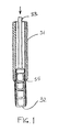
- Figure 1 shows a tubular sample cup cassette 31, in which single cup-like sample cups 32 have been placed one after another.
- the sample cup cassette 31 is placed in the cassette drum of the measuring device in an upright position so that the sample cups are in an upright position with the right side up.
- the sample cups 31 can be completely empty cups or the walls of the sample cups can be coated with marker substances required in the measuring.
- FIG. 1 shows a diagrammatic view of the thrust plunger 33, which in the measuring device is situated in conjunction with the sample cassette drum, as presented in more detail in the subsequent figures.
- FIG 2 shows diagrammatically the placing of the sample cup cassette 31 containing single sample cups 32 in the cassette drum 30 of the measuring device.
- Figure 2 only shows that part of the cassette drum 30 that forms the holder of the sample cup cassette 31.
- the sample cup cassette 31 is put into its place in such a way that the narrower part below the tapered point 35 is pushed into the opening between the limiters 36a and 36b.
- the opening is suitably wide, so that the sample cup cassette 31 can also be pushed into place in a slightly inclined position, whereby the cassette 31 remains with its tapered point 35 resting on the limiters 36a and 36b.
- the cassette 31 is pushed into an upright position, it is locked against the sill 37 of the holder, which sill is at the upper end of the cassette.
- the sample cup cassette 31 is provided with a bar code 34, which enables the sample cups 32 in the cassette to be identified.
- an opening 38 has been made in the holder of the cassette drum 30 for the bar code reader 39, which is at the centre of the drum.
- Identification of the sample cups is necessary when there are sample cups that have been provided with different coatings in the cassette drum 30. This being the case, one sample cup cassette 31 always only contains sample cups 32 that are coated in the same way. Therefore, the sample cup 32 that is to be used is always identified by the bar code 34 of the sample cup cassette 31.
- the sample cups 32 themselves do not bear any identifying marks. However, empty and uncoated sample cups can also be used in the measuring device, in which case it is naturally not necessary to identify them.
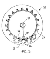
- Figure 3 shows the cassette drum 30 from above. It can be seen in the figure that the sample cup cassettes 31 have been placed on the circumference of the drum 30 in such a way that their bar codes 34 are facing the bar code reader 39 at the centre of the drum 30. In this way, the bar code reader 39 can read through the openings 38 the sample cup cassettes 31 that are on the drum 30.
- the computer controlling the measuring device is instructed to fetch for use a sample cup 32 corresponding to the measuring method. Then the cassette drum 30 is rotated so that the sample cup cassette 32 provided with the corresponding identification moves to the feeding station of the cassette drum 30. After that a sample cup suitable for the measuring method used is taken from this sample cassette 31.
- Figure 4 shows a diagrammatic view of the structure of the measuring device 20 and a diagrammatic view of the passage of a single sample cup 32 in the measuring device 20 by way of one example.
- the measuring device 20 has therefore been simplified, and neither do the sections of the various drums 30, 40 and 50 of the measuring device 20 represent a real sectional plane.
- the passage of a sample cup 32 in the measuring device 20 may, however, vary considerably, since the movements and operation of the drums 30, 40 and 50 can be changed. In this case the passage of the sample cup 32 in the measuring device 20 differs from that presented in figure 4.
- Figure 4 shows on the right the cassette drum 30 of the measuring device 20, in which cassette drum the sample cup cassettes 31 are placed.
- the cassette drum 30 is rotated so that the desired sample cup cassette 31 moves to the feeding point for the sample cups 32.
- the bar code reader 39 checks the bar code of the sample cup cassette 31 to ensure that the cassette that is at the feeding point contains sample cups 32 meant precisely for measuring this sample.
- a new sample cup 32a is taken for use from the sample cup cassette 31 in such a way that the plunger 33, which is in conjunction with the drum 30, presses the sample cups in the cassette 31 downwards.
- the sample cup 32a that is lowest in the cassette 31 is fed into the sample cup station of the first handling drum 40 of the measuring device 20.
- the first handling drum 40 is called an incubator drum, since only the sample dispensing and the incubation and shaking phases are carried out there.
- the tasks to be performed are distributed in a completely different way between the various handling drums 40 and 50 of the measuring device 20.
- the drum 40 rotates so that the sample cup 32a moves to the dispensing station, to the sample dispensing device 41.
- the sample cup that has moved to the dispensing device 41 is marked with reference number 32b.
- the dispenser probe 42 of the dispensing device 41 has dispensed the liquid sample solution into the sample cup 32b
- the reciprocating vibratory motion of the incubator drum 40 is started in order to incubate the sample.
- the incubator drum 40 is simultaneously a vibrator.
- the sample is shaken, for example, for 15 minutes at a temperature of 36°C.
- all the other preparatory phases required for measuring have been programmed to be carried out by the second handling drum 50.
- the tasks can also be divided in a different way between the handling drums 40 and 50. It is advantageous to divide the most time-consuming phases relating to measuring to different drums 40 and 50. Because different work phases can be carried out independently and simultaneously on both handling drums 40 and 50, the entire measuring process can be carried out in the shortest time possible. Incubation is the step that usually takes the most time, so the division of tasks presented in this example is advantageous. This is also the reason why the first handling drum 40 can take approximately three times as many sample cups 32 to be incubated as the second handling drum 50, where the work phases to be carried out take considerably less time.
- the second handling drum 50 rotates so that the sample cup moves to the washing station 51.
- the sample cup that is at the washing station 51 is marked with reference number 32d.
- the sample solution is discharged from the sample cup 32d, and the sample cup 32d is washed for example, for 30 seconds. After that the sample cup 32d is emptied and dried.
- the emptying of the sample cup 32d and the feeding and discharge of detergent is carried out by means of pipettes 52.
- the feeding and discharge pipettes are most advantageously separate, but for the sake of simplicity, figure 4 shows only one pipette 52 of the washing station 51.
- the sample cup drying station is also most advantageously a separate station, as is shown in the next figure, but it is not shown in figure 4. After the sample cup 32d has been washed and dried, measurement is carried out.
- the measuring is carried out on the coating layer on the inside of a dry sample cup.
- sample cups that contain fluid can also be measured in the measuring device shown in figure 4.
- the reagent solution is added to the sample cup before measuring.
- the reagent adding station can then be for example, at or next to the drying station marked with reference number 59 in figure 4.
- the handling drum 50 of the measuring device 20 rotates so that the sample cup moves to the measuring station 53.
- the sample cup at the measuring station 53 is marked with reference number 32e.
- the measuring head 54 of the measuring station 53 is above the sample cup 32e and the light shield 55 of the measuring head 54 is pressed down against the surface of the handling drum 50.
- Figure 4 also shows that to ensure impermeability to light, an annular groove 56 has been formed on the surface of the handling drum 50 at each sample cup.
- the handling drum 50 of the measuring device 20 rotates again. Now the measured sample cup comes to the discharge station.
- the sample cup to be discharged is marked in figure 4 with reference number 32f. It can be seen in figure 4 that there is an opening in the sample cup discharge station, in the bottom plate 57 under the handling drum 50, whereby the sample cup 32f is able to fall downwards. The downward movement of the plunger 58 ensures that the sample cup 32f has with certainty been discharged from the measuring device 20.
- FIG. 5 shows the equipment arrangement of the measuring device 20, seen from above.
- the sample receptacle containing the sample to be measured which sample receptacle is usually a test tube, is brought into the pipetting unit 21 and placed in the sample station 22, which in this example is called a test tube station.
- the pipetting unit 21 beside the test tube station 22, there is a sample diluting station 23, and at the opposite side of the test tube station 22, a pipette washing point 24.
- the pipette 42 of the dispensing device 41 of the pipetting unit 21 is used to perform dispensing of the sample into the sample cup, and possibly dilution.
- the identification code or number of the test tube that contains the sample to be measured is given to the measuring device 20.
- the identification can also be read from the bar code of the test tube.
- the measuring method is selected. If more than one test is to be carried out, the control device is instructed to fetch a corresponding number of sample cups for the measurements.
- the cassette drum 30 When the measurement is started, the cassette drum 30 is turned to a position where a sample cup cassette 31 containing sample cups 32 suited precisely for this measurement is at the sample cup feeding station. After that the sample cup 32 is fed to the first handling drum 40, i.e. to the incubator drum. Immediately after that the incubator drum 40 rotates and moves this sample cup to the dispensing station 25. If various sample cups have been taken onto the drum 40, they move one by one to the dispensing station 25.
- the various work phases of measurement proceed so that the dispensing pipette 42 of the dispensing device 41 takes sample solution from the test tube 22 and dispenses 10 ⁇ l of the solution and 20 ⁇ l of the buffer solution into the first sample cup in the dispensing station 25.
- the pipetting tip Before dispensing, the pipetting tip already contains the buffer, which is separated from the sample by a small air gap in the pipetting tip.
- sample solution and buffer solution are also dispensed into the other sample cups which are brought in their turn into the dispensing station 25.
- the reciprocating vibratory motion of the incubator drum 40 is started in order to incubate the samples.
- the samples are shaken for example, at a temperature of 36°C for 15 minutes.
- the incubation drum 40 rotates to a position where the first sample cup moves to the elevator station 26, where the sample cup is lifted to the handling drum 50.
- Other sample cups can also be lifted to the handling drum 50 in a similar manner already before washing, drying and measuring are started.
- the handling drum 50 After the sample cups have been lifted to the second handling drum 50, the handling drum 50 is rotated so that the first sample cup moves to the washing station 51. The sample cup is washed for 30 seconds, for example. After washing, the handling drum 50 rotates again so that the washed sample cup moves to the drying station 59 and the next sample cup to the washing station 51. The washing of the first sample cup and the drying of the second sample cup can then be carried out simultaneously, and they both take 30 seconds in this case.
- the second handling drum 50 rotates again so that the dried sample cup moves to the measuring head 54 of the measuring station 53.
- the second sample cup that has been in the wash moves into the drying station 59 and the third sample cup into the washing station.
- the handling drum 50 can be rotated so that the sample cups proceed at regular intervals from one handling phase to another. Then the measuring of the first sample cup, the drying of the second sample cup and the washing of the third sample cup occur simultaneously. In this way each sample cup is washed, dried and measured in turn and discharged from the discharge station 60 after measurement.
- the concentration and measuring results of each sample cup are shown on the display and also printed on paper.
- the measuring process can be carried out substantially faster when, besides the simultaneous work phases carried out at different handling drums 40 and 50, different work phases are also carried out simultaneously at the same handling drum 50.
- the division of tasks is such that in the measuring device 20 relating to the invention, all of the subsequent work phases are carried out simultaneously.
- sample cups 32 which are further on in the process, at different phases, are washed, dried, measured and discharged simultaneously at the second handling drum 50. It is clear that this procedure substantially accelerates the measuring process and the throughput of the sample cup 32 in the measuring device 20.
- the second handling drum 50 it is not always possible to use the second handling drum 50 in the way presented above. For example, there may be some reasons concerning the handling of the sample, which dictate that only one sample cup can be taken at a time from the incubator drum 40 to the handling drum 50, for example. Therefore the order of the various operations can be modified as necessary.
- the number of sample cups that can be taken to the second handling drum 50 at a time is also limited. For example, in figure 5, the handling drum 50 can clearly take fewer sample cups than the incubator drum 40.
- Figure 5 also shows a detail presented in the previous figure.
- annular grooves 56 On the surface of the handling drum 50, around the sample cups 32 annular grooves 56 have been formed, into which the light shield that is in conjunction with the measuring head 54 is pressed for the duration of the measurement thus ensuring that the space between the measuring head 54 and the sample cup 32 is impermeable to light.
- Figure 6 shows the second handling drum 50, seen from above.
- the sample cups are lifted to the handling drum 50 at the elevator station 26.
- Figure 6 also shows the location of the washing station 51, the drying station 59, the measuring head 54 and the discharge station 60 in relation to the handling drum 50.
- the handling drum 50 has eight places for sample cups, the places being grouped in a regular manner. This means that the angle of rotation a of the handling drum 50 is always 45° as the sample cup proceeds from one handling phase to another.
- handling stations 61, 62 and 63 which have been placed between the sample cup handling stations, can also be seen in figure 6.
- These handling stations are the washing head washing station 61, the reference well 62 and the opening 63 for the probe. They are meant to be used as necessary between the handling phases described above, as shown in the next figure.
- the handling drum 50 has been turned by an angle of ⁇ /2, i.e. by 22.5°, in which case the washing head washing station 61 is at the washing station 51, the reference well 62 is at the measuring head 54 of the measuring station 53 and the opening 63 is at the probe of the discharge station 60.
- This intermediate position of the handling drum 50 can be used at any time to wash the washing heads of the washing station 51 or to verify the reference standard.
- the opening 63 is included in the embodiment presented in this example because the downward movement of the probe of the discharge station 60 occurs simultaneously with the movement of the measuring head 54 towards the sample cup.
- the cassette drum 30 containing sample cups, the incubator drum 40 provided with a motion, and the sample handling drum 50 can each be rotated separately in either direction.
- each of these drums 30, 40 and 50 can operate independently and each perform their own task irrespective of one another. This enables the first samples to be measured and the next samples to be incubated simultaneously, for example.
- the sample cup 32 moves from one drum to another, the movement of these drums must naturally be co-ordinated and stopped for a while in a position where the sample cup can be moved.
- the members used to transfer and handle the sample cups 32 are drums 30, 40 and 50. These members can, however, be made so that they also move in any direction in the xy-coordinate system i.e. in the xy-plane. In this way, too, the movements of the sample cup handling members can be co-ordinated so that the sample cup can move from the cassette store to the incubator and from there further to the handling member and to the measuring station. In this case, too, it is essential that the handling members can operate independently and carry out different operations simultaneously.
- the measuring device 20 relating to the invention can be made to be completely computer-controlled and thus automatic.
- the user of the device only needs to place a sample receptacle containing a sample in the sample station 22.
- the sample is in a test tube that is brought to the test tube station 22, but the sample may also be in a different receptacle.
- the control devices of the measuring device 20 are not presented in the drawings.
- the measuring device 20 can also be made to be independent and continuously operating in such a way that a sample feeding device is connected to it, which device feeds test tubes containing samples or other sample receptacles to the sample station 22 of the measuring device.
Landscapes
- Physics & Mathematics (AREA)
- Health & Medical Sciences (AREA)
- Life Sciences & Earth Sciences (AREA)
- Chemical & Material Sciences (AREA)
- Analytical Chemistry (AREA)
- Biochemistry (AREA)
- General Health & Medical Sciences (AREA)
- General Physics & Mathematics (AREA)
- Immunology (AREA)
- Pathology (AREA)
- Automatic Analysis And Handling Materials Therefor (AREA)
Abstract
Description
- that the sample to be examined is transferred to the sample receptacle of the measuring device most advantageously by pipetting,
- that the information on the sample to be examined is transferred in the measuring device throughout the entire measuring process by transferring the said sample receptacle,
- and that the sample receptacle is handled in the measuring device in at least two independently operating handling members in such a way that at least two different handling phases are carried out simultaneously in the measuring device.
- the sample receptacle used for measuring in the measuring device is transferred from the sample receptacle store into the actual measuring device,
- within the measuring device, the sample receptacle is handled in at least two independently operating handling members,
- and all the various phases of the measuring process are divided to be performed by the said independently operating handling members.
- in the measuring device, the sample receptacle to be used for measuring is selected from the independently operating sample receptacle store for the first independent handling device of the actual measuring device, in which handling device at least the dispensing and incubation of the sample are carried out,
- and the sample receptacle is transferred from the first handling device to the second independently operating handling device in which the sample is at least measured and most advantageously the sample receptacle is also washed, dried and discharged.
- that the measuring device comprises members for transferring the sample receptacle within the measuring device,
- that the measuring device comprises at least two independently operating handling members and members for transferring the sample receptacle from one handling member to the second handling member,
- and that sample receptacle handling devices have been placed in conjunction with at least two independently operating handling members, with the aid of which handling devices at least two different handling phases can be carried out simultaneously on at least two sample receptacles.
- the measuring device comprises an independently operating sample receptacle store and at least two independently operating handling members,
- the sample receptacle store has members for transferring a measuring receptacle of the desired type to the handling member of the actual measuring device,
- that the measuring device comprises at least two of the following sample receptacle handling stations: a sample dispensing station, an incubation station, a sample receptacle washing station, a sample receptacle drying station, a sample measuring station and a sample receptacle discharge station,
- and the said handling stations have been divided so as to be in conjunction with at least two independently operating handling members so that at least two different handling stations can be made to operate simultaneously.
- the sample receptacles are sample cups and the sample receptacle store is a cassette drum on the circumference of which the sample cup cassettes containing sample cups have been placed,
- the independently operating handling members are rotating drums,
- and the cassette drum, the first sample cup handling drum and the second sample cup handling drum have been placed in conjunction with each other partly on top of each other so that the sample cup can be transferred directly from one drum to another.
- the first sample cup handling drum is an incubation station, in conjunction with which a sample cup feeding station and a sample dispensing station have been placed,
- a sample receptacle washing station, a sample receptacle drying station, a sample measuring station and a sample receptacle discharge station have been placed in conjunction with the second sample cup handling drum,
- and both handling drums operate independently, so that at least one handling station of the first handling drum can be made to operate simultaneously with at least one handling station of the second handling drum.
- the axles of the cassette drum and sample cup handling drums of the measuring device are parallel,
- and the measuring device comprises a sample cup feeding device and, between the first and the second handling drum, a sample cup transfer device, which devices have transfer plungers parallel to the axles of the said drums.
- Figure 1
- shows a section of a sample cup cassette, seen from the side.
- Figure 2
- shows the placing of a sample cup cassette in the cassette drum, seen from the side.
- Figure 3
- shows a cassette drum, seen from above.
- Figure 4
- shows a section of a diagrammatic view of the equipment arrangement, seen from the side.
- Figure 5
- shows a diagrammatic view of the equipment arrangement, seen from above.
- Figure 6
- shows a diagrammatic view of the sample cup handling drum, seen from above.
- Figure 7
- corresponds to figure 6 and shows the sample cup handling drum in another position.
Correspondingly, sample solution and buffer solution are also dispensed into the other sample cups which are brought in their turn into the dispensing
Claims (10)
- A sample handling method, in which method the sample is brought to the measuring device (20), steps relating to the measuring process are carried out on the sample and the sample is measured, characterized inthat the sample to be examined is transferred to the sample receptacle (32) of the measuring device (20) most advantageously by pipetting,that the information on the sample to be examined is transferred in the measuring device throughout the entire measuring process by transferring the said sample receptacle,and that the sample receptacle is handled in the measuring device in at least two independently operating handling members (40, 50) in such a way that at least two different handling phases are carried out simultaneously in the measuring device.
- A sample handling method as claimed in claim 1, characterized inthat the sample receptacle (32) used for measuring in the measuring device (20) is transferred from the sample receptacle store (30) into the actual measuring device,that within the measuring device the sample receptacle is handled in at least two independently operating handling members (40, 50),and that all the various phases of the measuring process are divided to be performed by the said independently operating handling members.
- A sample handling method as claimed in claim 1 or 2, characterized in that in the measuring device (20), at least two phases of the measuring process are carried out simultaneously in the same independently operating handling member (50).
- A sample handling method as claimed in claim 1, 2, or 3, characterized inthat in the measuring device (20), the sample receptacle (32) to be used for measuring is selected from the independently operating sample receptacle store (30) for the first independent handling device (40) of the actual measuring device, in which handling device at least the dispensing and incubation of the sample are carried out,and that the sample receptacle is transferred from the first handling device to the second independently operating handling device (50) in which the sample is at least measured and most advantageously the sample receptacle is also washed, dried and discharged.
- A diagnostic measuring device (20), characterized inthat the measuring device (20) comprises members for transferring the sample receptacle (32) within the measuring device,that the measuring device comprises at least two independently operating handling members (40, 50) and members (43) for transferring the sample receptacle from one handling member to the second handling member,and that sample receptacle handling devices (40, 51, 54, 59, 60) have been placed in conjunction with at least two independently operating handling members, with the aid of which handling devices at least two different handling phases can be carried out simultaneously on at least two sample receptacles (32a-f).
- A measuring device (20) as claimed in claim 5, characterized inthat the measuring device (20) comprises an independently operating sample receptacle store (30) and at least two independently operating handling members (40, 50),that the sample receptacle store has members (33) for transferring a measuring receptacle (32) of the desired type to the handling member (40) of the actual measuring device,that the measuring device comprises at least two of the following sample receptacle handling stations: a sample dispensing station (25), an incubation station (40), a sample receptacle washing station (51), a sample receptacle drying station (59), a sample measuring station (53) and a sample receptacle discharge station (60),and that the said handling stations have been divided so as to be in conjunction with at least two independently operating handling members so that at least two different handling stations can be made to operate simultaneously.
- A measuring device (20) as claimed in claim 5 or 6, characterized inthat the sample receptacles (32) are sample cups and the sample receptacle store (30) is a cassette drum on the circumference of which the sample cup cassettes (31) containing sample cups have been placed,that the independently operating handling members (40, 50) are rotating drums,and that the cassette drum (30), the first sample cup handling drum (40) and the second sample cup handling drum (50) have been placed in conjunction with each other partly on top of each other so that the sample cup (32) can be transferred directly from one drum to another.
- A measuring device (20) as claimed in claim 5, 6 or 7, characterized inthat the first sample cup (32) handling drum (40) is an incubation station, in conjunction with which a sample cup feeding station and a sample dispensing station (25) have been placed,that a sample receptacle washing station (51), a sample receptacle drying station (59), a sample measuring station (53) and a sample receptacle discharge station (60) have been placed in conjunction with the second sample cup handling drum (50),and that both handling drums (40, 50) operate independently, so that at least one handling station of the first handling drum can be made to operate simultaneously with at least one handling station of the second handling drum.
- A measuring device (20) as claimed in any of the claims 5-8, characterized in that at least two of the different handling stations (51, 59, 53, 60) that have been placed in conjunction with the second sample cup (32) handling drum (50) can be made to operate simultaneously.
- A measuring device (20) as claimed in any of the claims 5-9, characterized inthat the axles of the cassette drum (30) and sample cup (32) handling drums (40, 50) of the measuring device (20) are parallel,and that the measuring device comprises a sample cup feeding device and, between the first and the second handling drum, a sample cup transfer device (26), which devices have transfer plungers (33, 43) parallel to the axles of the said drums.
Applications Claiming Priority (2)
| Application Number | Priority Date | Filing Date | Title |
|---|---|---|---|
| FI990559A FI113703B (en) | 1999-03-12 | 1999-03-12 | Diagnostic measuring device |
| FI990559 | 1999-03-12 |
Publications (2)
| Publication Number | Publication Date |
|---|---|
| EP1037050A2 true EP1037050A2 (en) | 2000-09-20 |
| EP1037050A3 EP1037050A3 (en) | 2002-06-26 |
Family
ID=8554184
Family Applications (1)
| Application Number | Title | Priority Date | Filing Date |
|---|---|---|---|
| EP00660047A Withdrawn EP1037050A3 (en) | 1999-03-12 | 2000-03-09 | Method for handling samples and diagnostic measuring device |
Country Status (3)
| Country | Link |
|---|---|
| US (1) | US6551833B1 (en) |
| EP (1) | EP1037050A3 (en) |
| FI (1) | FI113703B (en) |
Cited By (5)
| Publication number | Priority date | Publication date | Assignee | Title |
|---|---|---|---|---|
| WO2003031988A3 (en) * | 2001-10-09 | 2003-12-18 | Eurolab Instr Gmbh | Photometric measuring device |
| EP1477813A1 (en) * | 2003-05-13 | 2004-11-17 | The Automation Partnership (Cambridge) Limited | Vial transfer apparatus |
| EP1491898A3 (en) * | 2003-06-24 | 2005-08-31 | RTS Thurnall PLC | Methods and apparatus for handling compound storage vessels |
| WO2005124365A3 (en) * | 2004-06-08 | 2006-02-16 | Biokit Sa | Tapered cuvette and method of collecting magnetic particles |
| US20130019697A1 (en) * | 2011-07-22 | 2013-01-24 | Constitution Medical, Inc. | Fluid sample preparation systems and methods |
Families Citing this family (24)
| Publication number | Priority date | Publication date | Assignee | Title |
|---|---|---|---|---|
| US20010036425A1 (en) * | 1995-10-12 | 2001-11-01 | Michel Gazeau | Device for transferring samples of micro-amounts of liquids |
| US6649128B1 (en) * | 1998-09-23 | 2003-11-18 | Randox Laboratories Ltd | Assay device processing instrument |
| WO2003079028A1 (en) * | 2002-03-11 | 2003-09-25 | Leco Corporation | Automatic crucible and sample loading system and method |
| US6890604B2 (en) * | 2002-05-13 | 2005-05-10 | Trio Industries Holdings, Llc | Method and system for powder coating passage doors |
| EP1516669A1 (en) * | 2003-09-19 | 2005-03-23 | The Automation Partnership (Cambridge) Limited | Apparatus for sealing tubes |
| US20050220670A1 (en) * | 2004-03-31 | 2005-10-06 | Thomas Palmieri | Multipath access system for use in an automated immunoassay analyzer |
| US10697987B2 (en) | 2006-01-23 | 2020-06-30 | Brooks Automation, Inc. | Automated system for storing, retrieving and managing samples |
| WO2007087546A2 (en) | 2006-01-23 | 2007-08-02 | Nexus Biosystems, Inc. | Automated system for storing, retreiving and managing samples |
| EP1970711A1 (en) * | 2007-03-16 | 2008-09-17 | Radiometer Medical ApS | Reagent cup device |
| US8323565B2 (en) | 2007-04-12 | 2012-12-04 | Leco Corporation | Crucible shuttle assembly and method of operation |
| US8657550B2 (en) * | 2007-04-12 | 2014-02-25 | Leco Corporation | Crucible shuttle assembly with linearly moving carriage |
| KR20100083030A (en) * | 2009-01-12 | 2010-07-21 | 삼성전자주식회사 | Loading apparatus loading cartridge containing reactant into chambers of reaction device |
| WO2014144627A1 (en) | 2013-03-15 | 2014-09-18 | Abbott Laboratories | Automated diagnostic analyzers having rear accessible track systems and related methods |
| ES2970108T3 (en) | 2013-03-15 | 2024-05-27 | Abbott Lab | Diagnostic analyzers with pretreatment carousels and related methods |
| JP6351703B2 (en) | 2013-03-15 | 2018-07-04 | アボット・ラボラトリーズAbbott Laboratories | Automatic diagnostic analyzer with vertically arranged carousel and related methods |
| GB2517750B (en) * | 2013-08-30 | 2018-04-25 | Thermo Electron Mfg Ltd | Laboratory container transfer device |
| WO2015160984A1 (en) * | 2014-04-18 | 2015-10-22 | Siemens Healthcare Diagnostics Inc. | Reaction vessel handling apparatus, testing apparatus, and methods using same |
| EP3314269A4 (en) * | 2015-06-26 | 2019-01-23 | Abbott Laboratories | Reaction vessel exchanger device for a diagnostic analyzer |
| AU2017220028B2 (en) | 2016-02-17 | 2022-04-28 | Becton, Dickinson And Company | Automated sample preparation system for diagnostic testing of same |
| CA3019789C (en) | 2016-04-22 | 2025-11-18 | Becton, Dickinson And Company | Automated diagnostic analyzer and method for its operation |
| CN109073664B (en) | 2016-04-22 | 2022-12-06 | 贝克顿·迪金森公司 | Automatic diagnostic analyzer and method of operation thereof |
| JP6741629B2 (en) * | 2017-08-10 | 2020-08-19 | 株式会社日立製作所 | Analysis device, analysis method |
| CN111551758A (en) * | 2017-10-19 | 2020-08-18 | 深圳迎凯生物科技有限公司 | Automatic analyzer |
| CN114923974B (en) * | 2022-07-14 | 2022-10-04 | 深圳中食匠心食品有限公司 | Portable bread heavy metal detection device and detection method thereof |
Family Cites Families (23)
| Publication number | Priority date | Publication date | Assignee | Title |
|---|---|---|---|---|
| DE3130245A1 (en) * | 1981-07-31 | 1983-02-17 | Bodenseewerk Perkin-Elmer & Co GmbH, 7770 Überlingen | SAMPLER FOR GAS SAMPLING IN GAS CHROMATOGRAPHY |
| JPH0754326B2 (en) * | 1986-06-24 | 1995-06-07 | 株式会社東芝 | Automatic chemical analyzer |
| DE3783593T2 (en) * | 1986-07-11 | 1993-05-19 | Beckman Instruments Inc | METHOD FOR OPERATING AN ANALYZER. |
| US4857471A (en) * | 1987-07-20 | 1989-08-15 | Eastman Kodak Company | Analyzer with wash station separate from incubator |
| US5087423A (en) | 1988-10-20 | 1992-02-11 | Olympus Optical Co., Ltd. | Automatic analyzing apparatus comprising a plurality of analyzing modules |
| US5585068A (en) * | 1990-02-20 | 1996-12-17 | Biochemical Diagnostics, Inc. | Apparatus for automatically separating a compound from a plurality of discrete liquid specimens |
| EP0596883A4 (en) * | 1991-07-26 | 1994-12-07 | Cirrus Diagnostics Inc | AUTOMATED ANALYZER FOR IMMUNOLOGICAL ASSAYS. |
| US5380487A (en) | 1992-05-05 | 1995-01-10 | Pasteur Sanofi Diagnostics | Device for automatic chemical analysis |
| US5244633A (en) * | 1992-05-22 | 1993-09-14 | Eastman Kodak Company | Analyzer incubator with plural independently driven rings supporting cuvettes |
| JP2616360B2 (en) | 1992-09-30 | 1997-06-04 | 株式会社島津製作所 | Blood coagulation analyzer |
| US5271896A (en) | 1993-04-16 | 1993-12-21 | Eastman Kodak Company | Plunger and driver mechanism for an analyzer |
| US5681530A (en) * | 1993-06-11 | 1997-10-28 | Ortho Diagnostic Systems Inc. | Transport system for fluid analysis instrument |
| US5350564A (en) * | 1993-06-28 | 1994-09-27 | Baxter Diagnostics Inc. | Automated chemical analyzer with apparatus and method for conveying and temporary storage of sample tubes |
| US5374395A (en) * | 1993-10-14 | 1994-12-20 | Amoco Corporation | Diagnostics instrument |
| US5441895A (en) * | 1993-12-07 | 1995-08-15 | Jakubowicz; Raymond F. | Reagent cup shape allowing stacking without dislodging reagent |
| US5441891A (en) * | 1994-05-26 | 1995-08-15 | Burkovich; Robert A. | Transfer mechanism within an incubator |
| US5456883A (en) * | 1994-06-27 | 1995-10-10 | Johnson & Johnson Clinical Diagnostics, Inc. | Mechanism for reading and removing reaction cuvettes in an incubator |
| HU223869B1 (en) | 1995-02-16 | 2005-02-28 | Quest Diagnostics Incorporated | Automated apparatus for submitting samples to one or more selected test procedures at test stations |
| WO1997041445A1 (en) * | 1996-04-26 | 1997-11-06 | Dade International Inc. | Method and apparatus for pre-treating samples in an automatic chemical analyzer |
| US5885529A (en) * | 1996-06-28 | 1999-03-23 | Dpc Cirrus, Inc. | Automated immunoassay analyzer |
| US5853666A (en) * | 1997-02-12 | 1998-12-29 | Biomerieux Vitek, Inc. | Optical reader and sample card transport stations for biological sample testing machine |
| JPH10332706A (en) * | 1997-05-28 | 1998-12-18 | Kyowa Medex Co Ltd | Dilution device of automatic analyzer |
| US6117391A (en) * | 1998-06-18 | 2000-09-12 | Bayer Corporation | Cup handling subsystem for an automated clinical chemistry analyzer system |
-
1999
- 1999-03-12 FI FI990559A patent/FI113703B/en not_active IP Right Cessation
-
2000
- 2000-03-09 EP EP00660047A patent/EP1037050A3/en not_active Withdrawn
- 2000-03-10 US US09/523,517 patent/US6551833B1/en not_active Expired - Lifetime
Cited By (11)
| Publication number | Priority date | Publication date | Assignee | Title |
|---|---|---|---|---|
| WO2003031988A3 (en) * | 2001-10-09 | 2003-12-18 | Eurolab Instr Gmbh | Photometric measuring device |
| EP1477813A1 (en) * | 2003-05-13 | 2004-11-17 | The Automation Partnership (Cambridge) Limited | Vial transfer apparatus |
| EP1491898A3 (en) * | 2003-06-24 | 2005-08-31 | RTS Thurnall PLC | Methods and apparatus for handling compound storage vessels |
| WO2005124365A3 (en) * | 2004-06-08 | 2006-02-16 | Biokit Sa | Tapered cuvette and method of collecting magnetic particles |
| AU2005255403B2 (en) * | 2004-06-08 | 2010-07-15 | Biokit, S.A. | Tapered cuvette and method of collecting magnetic particles |
| US8211386B2 (en) | 2004-06-08 | 2012-07-03 | Biokit, S.A. | Tapered cuvette and method of collecting magnetic particles |
| US8476080B2 (en) | 2004-06-08 | 2013-07-02 | Biokit, S.A. | Tapered cuvette and method of collecting magnetic particles |
| US20130019697A1 (en) * | 2011-07-22 | 2013-01-24 | Constitution Medical, Inc. | Fluid sample preparation systems and methods |
| US9057672B2 (en) * | 2011-07-22 | 2015-06-16 | Roche Diagnostics Hematology, Inc. | Fluid sample preparation systems and methods |
| US9588026B2 (en) | 2011-07-22 | 2017-03-07 | Roche Diagnostics Hematology, Inc. | Fluid sample preparation systems and methods |
| US10345205B2 (en) | 2011-07-22 | 2019-07-09 | Roche Diagnostics Hematology, Inc. | Fluid sample preparation systems and methods |
Also Published As
| Publication number | Publication date |
|---|---|
| FI113703B (en) | 2004-05-31 |
| US6551833B1 (en) | 2003-04-22 |
| FI990559A0 (en) | 1999-03-12 |
| FI990559A7 (en) | 2000-09-13 |
| EP1037050A3 (en) | 2002-06-26 |
Similar Documents
| Publication | Publication Date | Title |
|---|---|---|
| US6551833B1 (en) | Method for handling samples and diagnostic measuring device | |
| EP0583078B1 (en) | Method and apparatus for handling samples | |
| US7341691B2 (en) | Automatic analyzing apparatus | |
| JP4890699B2 (en) | Analytical apparatus and method for measuring sample quality | |
| US6752960B1 (en) | Automatic analysis apparatus | |
| US4287155A (en) | Sample tray and carrier for chemical analyzer | |
| JP3428426B2 (en) | Sample analysis system | |
| US5213761A (en) | Automatic chemical analyzer having an improved delivery mechanism | |
| JP3229498B2 (en) | Automatic sample analysis method and apparatus | |
| EP1577675B1 (en) | Apparatus and method for handling fluids for analysis | |
| EP1102994B1 (en) | Automated immunoassay apparatus with flexible pick-up arm | |
| JP2927082B2 (en) | Analysis method and analyzer for liquid sample | |
| US5264182A (en) | Sample and reagent delivery device with a probe and probe supporting member for preventing contamination | |
| EP2073934A1 (en) | Micro-sample cup rack adapter | |
| CN109975567B (en) | Control method and system of chemiluminescence detector and chemiluminescence detector | |
| JP2611609B2 (en) | Clinical compound analyzer | |
| JPH04106472A (en) | Automatic chemical analyzer | |
| JP2025134797A (en) | Automated diagnostic analyzer for liquid samples | |
| JPS6049258B2 (en) | Sample sorter in automatic analyzer | |
| JPH0694728A (en) | Clinical testing equipment sample pallet | |
| JP7114794B1 (en) | Automatic analysis device and automatic analysis method | |
| EP1293782B1 (en) | Automatic analyzing apparatus | |
| JP2774052B2 (en) | Liquid sample automatic analyzer | |
| CN114076734A (en) | Method of Operation for Chemiluminescence Analyzers | |
| JP7798534B2 (en) | automatic analyzer |
Legal Events
| Date | Code | Title | Description |
|---|---|---|---|
| PUAI | Public reference made under article 153(3) epc to a published international application that has entered the european phase |
Free format text: ORIGINAL CODE: 0009012 |
|
| AK | Designated contracting states |
Kind code of ref document: A2 Designated state(s): AT BE CH CY DE DK ES FI FR GB GR IE IT LI LU MC NL PT SE |
|
| AX | Request for extension of the european patent |
Free format text: AL;LT;LV;MK;RO;SI |
|
| RAP1 | Party data changed (applicant data changed or rights of an application transferred) |
Owner name: INNOTRAC DIAGNOSTICS OY |
|
| PUAL | Search report despatched |
Free format text: ORIGINAL CODE: 0009013 |
|
| AK | Designated contracting states |
Kind code of ref document: A3 Designated state(s): AT BE CH CY DE DK ES FI FR GB GR IE IT LI LU MC NL PT SE |
|
| AX | Request for extension of the european patent |
Free format text: AL;LT;LV;MK;RO;SI |
|
| AKX | Designation fees paid | ||
| REG | Reference to a national code |
Ref country code: DE Ref legal event code: 8566 |
|
| STAA | Information on the status of an ep patent application or granted ep patent |
Free format text: STATUS: THE APPLICATION IS DEEMED TO BE WITHDRAWN |
|
| 18D | Application deemed to be withdrawn |
Effective date: 20021230 |