EP1045275A1 - Electrochromic mirror - Google Patents
Electrochromic mirror Download PDFInfo
- Publication number
- EP1045275A1 EP1045275A1 EP98951693A EP98951693A EP1045275A1 EP 1045275 A1 EP1045275 A1 EP 1045275A1 EP 98951693 A EP98951693 A EP 98951693A EP 98951693 A EP98951693 A EP 98951693A EP 1045275 A1 EP1045275 A1 EP 1045275A1
- Authority
- EP
- European Patent Office
- Prior art keywords
- electrochromic
- formula
- compound
- layer
- substrate
- Prior art date
- Legal status (The legal status is an assumption and is not a legal conclusion. Google has not performed a legal analysis and makes no representation as to the accuracy of the status listed.)
- Withdrawn
Links
Images

Classifications
-
- C—CHEMISTRY; METALLURGY
- C09—DYES; PAINTS; POLISHES; NATURAL RESINS; ADHESIVES; COMPOSITIONS NOT OTHERWISE PROVIDED FOR; APPLICATIONS OF MATERIALS NOT OTHERWISE PROVIDED FOR
- C09K—MATERIALS FOR MISCELLANEOUS APPLICATIONS, NOT PROVIDED FOR ELSEWHERE
- C09K9/00—Tenebrescent materials, i.e. materials for which the range of wavelengths for energy absorption is changed as a result of excitation by some form of energy
- C09K9/02—Organic tenebrescent materials
-
- G—PHYSICS
- G02—OPTICS
- G02F—OPTICAL DEVICES OR ARRANGEMENTS FOR THE CONTROL OF LIGHT BY MODIFICATION OF THE OPTICAL PROPERTIES OF THE MEDIA OF THE ELEMENTS INVOLVED THEREIN; NON-LINEAR OPTICS; FREQUENCY-CHANGING OF LIGHT; OPTICAL LOGIC ELEMENTS; OPTICAL ANALOGUE/DIGITAL CONVERTERS
- G02F1/00—Devices or arrangements for the control of the intensity, colour, phase, polarisation or direction of light arriving from an independent light source, e.g. switching, gating or modulating; Non-linear optics
- G02F1/01—Devices or arrangements for the control of the intensity, colour, phase, polarisation or direction of light arriving from an independent light source, e.g. switching, gating or modulating; Non-linear optics for the control of the intensity, phase, polarisation or colour
- G02F1/15—Devices or arrangements for the control of the intensity, colour, phase, polarisation or direction of light arriving from an independent light source, e.g. switching, gating or modulating; Non-linear optics for the control of the intensity, phase, polarisation or colour based on an electrochromic effect
- G02F1/1503—Devices or arrangements for the control of the intensity, colour, phase, polarisation or direction of light arriving from an independent light source, e.g. switching, gating or modulating; Non-linear optics for the control of the intensity, phase, polarisation or colour based on an electrochromic effect caused by oxidation-reduction reactions in organic liquid solutions, e.g. viologen solutions
-
- C—CHEMISTRY; METALLURGY
- C09—DYES; PAINTS; POLISHES; NATURAL RESINS; ADHESIVES; COMPOSITIONS NOT OTHERWISE PROVIDED FOR; APPLICATIONS OF MATERIALS NOT OTHERWISE PROVIDED FOR
- C09K—MATERIALS FOR MISCELLANEOUS APPLICATIONS, NOT PROVIDED FOR ELSEWHERE
- C09K2211/00—Chemical nature of organic luminescent or tenebrescent compounds
- C09K2211/14—Macromolecular compounds
- C09K2211/1441—Heterocyclic
- C09K2211/1466—Heterocyclic containing nitrogen as the only heteroatom
-
- G—PHYSICS
- G02—OPTICS
- G02F—OPTICAL DEVICES OR ARRANGEMENTS FOR THE CONTROL OF LIGHT BY MODIFICATION OF THE OPTICAL PROPERTIES OF THE MEDIA OF THE ELEMENTS INVOLVED THEREIN; NON-LINEAR OPTICS; FREQUENCY-CHANGING OF LIGHT; OPTICAL LOGIC ELEMENTS; OPTICAL ANALOGUE/DIGITAL CONVERTERS
- G02F1/00—Devices or arrangements for the control of the intensity, colour, phase, polarisation or direction of light arriving from an independent light source, e.g. switching, gating or modulating; Non-linear optics
- G02F1/01—Devices or arrangements for the control of the intensity, colour, phase, polarisation or direction of light arriving from an independent light source, e.g. switching, gating or modulating; Non-linear optics for the control of the intensity, phase, polarisation or colour
- G02F1/15—Devices or arrangements for the control of the intensity, colour, phase, polarisation or direction of light arriving from an independent light source, e.g. switching, gating or modulating; Non-linear optics for the control of the intensity, phase, polarisation or colour based on an electrochromic effect
- G02F1/153—Constructional details
- G02F1/157—Structural association of cells with optical devices, e.g. reflectors or illuminating devices
Definitions
- This invention relates to electrochromic devices and more particularly electrochromic mirrors which are useful as light controllable elements such as light controllable windows (smart windows) for buildings, automobiles and passenger vehicles and various types of light controllable glasses for indoor decoration or partitions; display devices; antidazzle mirrors for automobiles; and decoration mirrors for indoor use.
- light controllable elements such as light controllable windows (smart windows) for buildings, automobiles and passenger vehicles and various types of light controllable glasses for indoor decoration or partitions; display devices; antidazzle mirrors for automobiles; and decoration mirrors for indoor use.
- a conventional electrochromic device such as a conventional type of antidazzle mirror as disclosed in Japanese Patent Laid-Open Publication No. 63-18336 is known which mirror comprises a chromogenic material in the form of a film obtained by sputtering or vacuum-depositing an inorganic oxide such as tungsten oxide (WO 3 ) over a transparent electrically conductive film.
- a chromogenic material in the form of a film obtained by sputtering or vacuum-depositing an inorganic oxide such as tungsten oxide (WO 3 ) over a transparent electrically conductive film.
- Such an electrochromic antidazzle mirror is manufacture by a film forming operation carried out under vacuum conditions, resulting in increased production cost.
- a demand has therefore been placed on an electrochromic mirror which can be manufactured with inexpensive materials and by a simple and easy method.
- a method has also been proposed in which to use a viologen compound as a component constituting an electrochromic device.
- viologen compound as a component constituting an electrochromic device.
- further improvements on this method are demanded because the purification of viologen requires time and effort and the life or duration of coloration or decoloration functions of the device may be shortened, resulting from impurities such as an acid even in small amounts mixed into the system of the device.
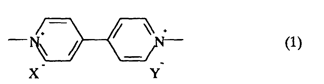
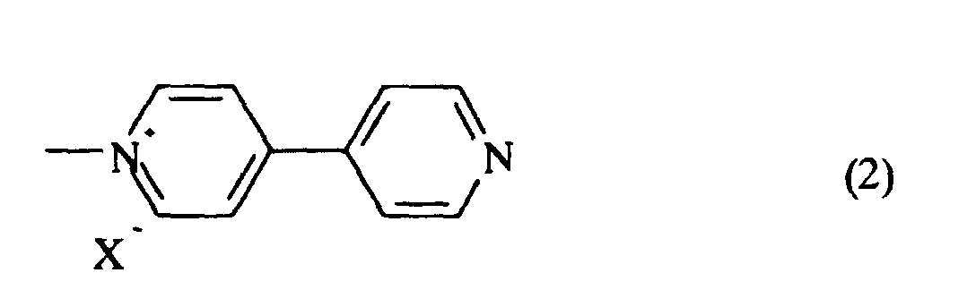
- an electrochromic device comprising two conductive substrates, at least one of which is transparent, an ion conductive layer disposed therebetween and an electrochromic color developing layer disposed between the ion conductive layer and at least either one of the two conductive substrates and containing (A) a compound having a viologen structure represented by the formula wherein X - and Y - may be the same or different and each are a counter anion selected from the group consisting of a halogen anion, ClO 4 - , BF 4 - , PF 6 - , CH 3 COO - and CH 3 (C 6 H 4 )SO 3 - and (B) 4,4'-dipyridyl and/or a mono-substituted 4,4'-dipyridinium salt represented by the formula wherein X - is a counter anion selected from the group consisting of a halogen anion, ClO 4 - , BF 4 - , PF 6
- an electrochromic device all of which components are solid.
- an electrochromic mirror which comprises a reflective conductive substrate, a transparent substrate, an ion conductive layer disposed therebetween and an electrochromic color developing layer disposed between the ion conductive and the reflective conductive substrate or transparent substrate.
- the two conductive substrates are used in the present invention. These substrates may be any type of substrates as long as they function as an electrode. More specifically, each of the conductive substrate may be those entirely formed from an electrically conductive material or those comprised of a non-electrically conductive substrate and an electrode layer disposed thereon.
- An electrochromic mirror according to the present invention includes a pair of such electrically conductive substrates, at least one of which is transparent and the other of which is reflective of light or non-reflective opaque. These transparent, reflective and opaque substrates may have a flat or curved surface and may be deformable under stress.
- the transparent conductive substrate may generally exemplified by a laminate comprising a transparent substrate and a transparent electrode layer formed thereon.
- the reflective electrically conductive substrate may be exemplified by (1) a laminate comprising a transparent or opaque substrate and a reflective electrode layer formed thereon, (2) a laminate comprising a substrate having a transparent electrode layer on one of its surfaces and a reflective electrode layer on the other surface, (3) a laminate comprising a transparent substrate having a reflective layer formed thereon and further a transparent electrode layer formed thereon and (4) a plate-like substrate which itself functions as a reflective layer and an electrode.
- the non-reflective opaque conductive substrate is exemplified by a substrate selected from various metal plates or a laminate comprising a non-conductive opaque substrate such as various opaque plastics, ceramics, glasses and woods and an electrode formed on its surface.
- the transparent substrate may thus be a color or colorless glass, a reinforced glass and a resin of color or colorless transparency.
- a resin include polyethylene terephthalate, polyamide, polysulfone, polyether sulfone, polyether etherketone, polyphenylene sulfide, polycarbonate, polyimide, polymethyl methacrylate and polystyrene.
- transparency designates an optical transmission which is in the range from 10 to 100 percent.
- the substrates used for the invention have a smooth surface at normal temperature.
- the transparent electrode layer there is no particular restriction to the transparent electrode layer as long as it meets the requirements for achieving the purpose of the present invention.
- the electrode layer include electrically conductive films such as thin films of various types of metals such as gold, silver, chrome, copper and tungsten or of metal oxides such as ITO (In 2 O 3 -SnO 2 ), tin oxide, silver oxide, zinc oxide and vanadium oxide.
- the electrode has a film thickness in the range of usually 100 to 5,000 and preferably 500 to 3,000 angstrom.
- the surface resistance of the electrode is usually in the range of 0.5-500 and preferably 1 -50 ⁇ /sq.
- Electrode layer No particular limitation is imposed on a method of forming the electrode layer. Any suitable conventional methods may be employed, depending upon the kind of metal and metal oxide constituting the electrode. In general, the formation of the electrode layer is carried out by vacuum evaporation, ion plating, sputtering and a sol-gel method. The thickness of the electrode layer is selected within the range such that the transparency thereof is not affected.
- the electrode layer may be partially provided with an opaque electrode-activator for the purpose of imparting oxidation-reduction capability, electric conductivity and electric double layer capacitance, the electrode-activator being provided in an amount such that the transparency of the entire electrode layer is not harmed.
- Electrode activators eligible for the purpose of the invention are metals such as copper, silver, gold, platinum, iron, tungsten, titanium and lithium, organic materials having oxidation-reduction capability such as polyaniline, polythiophen, polypyrrole and phthalocyanine, carbon materials such as active carbon and graphite and metal oxides such as V 2 O 5 , WO 3 , MnO 2 , NiO and Ir 2 O 3 and mixtures thereof.
- a variety of resins may be used for integrating the electrode activator in the electrode.
- the opaque electrode activator may applied onto an electrode by forming on an ITO transparent electrode a composition comprising an active carbon fiber, graphite and an acrylic resin into a micro pattern in the shape of stripes or by forming on a thin-film of gold a composition comprising V 2 O 5 , acetylene black and butyl rubber in the shape of a mesh.
- Eligible reflective electrode layers include metal films such as of gold, platinum, tungsten, tantalum, rhenium, osmium, iridium, silver, nickel and palladium and alloy films such as of platinum-palladium, platinum-rhodium and stainless steel.
- the reflective electrode layer is necessarily disposed onto a substrate or a transparent substrate with the reflectiveness and specularity of the layer maintained.
- the reflective electrode layer is formed onto a substrate by any suitable conventional method such as vacuum deposition, ion-plating and sputtering.
- the substrate may be transparent or opaque.
- Specific examples of the substrate include those as exemplified with respect to the transparent substrate described above, a variety of plastics, resins, glasses, woods and stones.
- the plate-like substrate having a reflective layer and functioning as an electrode may be exemplified by the substrates exemplified with respect to the reflective electrode among which are self-supportive.
- An ion conductive material used for the inventive electrochromic mirror is disposed so as to be sandwiched between a reflective electrically conductive substrate or non-reflective opaque substrate and a transparent electrically conductive substrate (these substrates are hereinafter referred to as counter-conductive substrates).
- a reflective electrically conductive substrate or non-reflective opaque substrate and a transparent electrically conductive substrate (these substrates are hereinafter referred to as counter-conductive substrates).
- counter-conductive substrates No particular limitation is imposed on a method of disposing the ion conductive material between the counter-conductive substrates.
- a method may be employed in which the ion conductive material is injected into the space provided between the substrates which are placed, facing each other and then sealed at the edges of the opposed surfaces, by vacuum injection, atmospheric injection or a meniscus method.
- a method may be employed in which the layer of the ion conductive material is formed on the electrode layer of one of the electrically conductive substrates and then put together with the other electrically conductive substrate. Further alternatively, a method may be employed in which a film-like ion conductive material is inserted between a pair of glasses to form a laminated glass.
- the term "ion conductive material” designates materials which can color, decolor and discolor an electrochromic material hereinafter described.
- the ion conductive material has preferably an ion conductivity of 1 x 10 -7 S/cm or more at room temperature. No particular limitation is imposed on the ion conductive material, which may thus be liquid, gel or solid. Solid ion conductive materials are particularly preferred for the purpose of the invention so as to obtain an electrochromic mirror which is overall solid and excelled in various performances for practical usage.
- Eligible liquid ion conductive materials are those dissolving a supporting electrolyte such as salts, acids and alkalis in a solvent.
- any suitable solvents may be used as long as they can dissolve a supporting electrolyte, preferred are those having polarity.
- organic polar solvent such as methanol, ethanol, propylene carbonate, ethylene carbonate, dimethylsulfoxide, dimethoxyethane, acetonitrile, r-butyrolactone, r-valerolactone, sulforan, dimethylformamide, dimethoxyethane, tetrahydrofuran, propionnitrile, glutaronitrile, adiponitrile, methoxyacetonitrile, dimethylacetoamide, methylpyrrolidinone, dimethylsulfoxide, dioxolane, trimethylphosphate and polyethylene glycol.
- an organic polar solvent such as methanol, ethanol, propylene carbonate, ethylene carbonate, dimethylsulfoxide, dimethoxyethane, acetonitrile, r-butyrolactone, r-valerolactone
- salts used as a supporting electrolyte may be alkali metal salts, inorganic ion salts such as alkaline earth metal salts, quaternary ammonium salts and cyclic quaternary ammonium salts.
- alkali metal salts of lithium, sodium or potassium such as LiClO 4 , LiSCN, LiBF 4 .
- Acids used as a supporting electrolyte may be exemplified by inorganic acids and organic acids, specific examples of which include sulfuric acid, hydrochloric acid, phosphoric acid, sulfonic acid carboxylic acid.
- Alkalis used as a supporting electrolyte include sodium hydroxide, potassium hydroxide and lithium hydroxide.
- the gelatinized-liquid ion conductive material may be those which are gelatinized or made to be viscous by adding a polymer or a gelatinizer to the above-mentioned liquid ion conductive material.
- polymers which thus may be polyacrylonitrile, carboxymethylcellulose, polyvinyl chloride, polyethylene oxide, polyurethane, polyacrylate, polyamide, polyacrylamide, cellulose, polyester, polypropyleneoxide and nafion.
- gelatinizers are oxyethylenemethacrylate, oxyethyleneacrylate, urethaneacrylate, acrylamide and agar-agar.
- solid ion conductive material No particular limitation is imposed on the solid ion conductive material as long as it is solid at room temperature and ion conductive.
- Preferred examples of such solid ion conductive materials are polyethyleneoxide, the polymer of oxyethylenemethacrylate, nafion, polystylene sulfonate, Li 3 N, Na- ⁇ -Al 2 O 3 and Sn(HPO 4 ) 2 H 2 O.
- Particularly preferred are polymer solid electrolytes obtained by polymerizing a polyethyleneoxide-based compound, an oxyalkyleneacrylate-based compound or a urethaneacrylate-based compound.
- a first examples of such polymer solid electrolytes are those obtained by solidifying a composition (hereinafter referred to as Composition A) containing the above-described organic polar solvent and supporting electrolyte and a urethaneacrylate of the formula wherein R 1 and R 2 may be the same or different and are each a group of formula (4), (5) or (6) below, R 3 and R 4 may be the same or different and are each a C 1 -C 20 , preferably C 2 -C 12 divalent hydrocarbon residue, Y is selected from a polyether unit, a polyester unit , a polycarbonate unit and the mixed unit thereof and n is an integer of 1-100, preferably 1-50 and more preferably 1-20.
- Composition A containing the above-described organic polar solvent and supporting electrolyte and a urethaneacrylate of the formula wherein R 1 and R 2 may be the same or different and are each a group of formula (4), (5) or (6) below, R 3 and R 4 may be the same or
- Formulae (4), (5) and (6) are represented by wherein R 5 , R 6 and R 7 may be the same or different and are each a hydrogen atom or a C 1 -C 3 alkyl group and R 8 is a C 1 -C 20 , preferably C 2 -C 8 organic residue of divalent through quatervalent.
- organic residues are a hydrocarbon residue such as alkyltolyl, alkyltetratolyl and alkylene of the formula wherein R 9 is a C 1 -C 3 alkyl group or hydrogen, p is an integer of 0-6 and if p is greater than 2 the groups of R 9 may be the same or different.
- the hydrocarbon residue may be a group part of which hydrogen atoms are substituted by an oxygen-containing hydrocarbon group such as a C 1 -C 6 , preferably C 1 -C 3 alkoxy group and a C 6 -C 12 aryloxy group.
- an oxygen-containing hydrocarbon group such as a C 1 -C 6 , preferably C 1 -C 3 alkoxy group and a C 6 -C 12 aryloxy group.
- Each of the divalent hydrocarbon residues represented by R 3 and R 4 in formula (3) is exemplified by a divalent chain-like hydrocarbon group, an aromatic hydrocarbon group and an alicyclic-containing hydrocarbon group.
- Specific examples of the chain-like divalent hydrocarbon group are those represented by formula (7) above.
- aromatic hydrocarbon group and alicyclic-containing hydrocarbon group are those represented by the following formulae : wherein R 10 and R 11 may be the same or different and each are a phenylene group, a phenylene group having an alkyl subsutituent, a cycloalkylene group and a cycloalkylene group having an alkyl substituent, R 12 , R 13 , R 14 and R 15 may be the same or different and each are a hydrogen atom or a C 1 -C 3 alkyl group and q is an integer from 1 to 5.
- Y indicates a polyether unit, a polyester unit, a polycarbonate unit and a mixed unit thereof .
- Each of these units is represented by the following formulae :
- R 16 through R 21 may be the same or different and are each a C 1 -C 20 , preferably C 2 -C 12 divalent hydrocarbon residue.
- R 21 is particularly preferably a C 2 -C 6 divalent hydrocarbon residue.
- R 16 through R 21 are preferably straight or branched alkylene groups among which methylene, ethylene, trimethylene, tetramethylene, pentamethylene, hexamethylene and propylene groups are preferred for R 18 , and ethylene and propylene groups are preferred for R 16 , R 17 and R 19 through R 21 .
- the letter “m” in formula (a) is an integer of 2-300, preferably 10-200, the letter “r” is an integer of 1-300, preferably 2-200, the letter “s” is an integer of 1-200, preferably 2-100, the letter “t” is an integer of 1-200, preferably 2-100 and the letter “u” is an integer of 1-300, preferably 10-200.
- Each unit represented by formulae (a) through (d) may be a copolymer of the same or different units. Namely, if there exist a plurality of groups of each R 16 through R 21 , groups of each R 16 , R 17 , R 18 ,R 19 , R 20 and R 21 may be the same or different. Preferred examples of such copolymers include copolymers of ethylene oxide and copolymers of propylene oxide.
- An urethaneacrylate of formula (II) has a molecular weight in the range of 2,500-30,000, preferably 3,000-20,000.
- the urethaneacrylate has preferably 2-6, more preferably 2-4 polymerization functional groups per molecule.
- the urethaneacrylate may be prepared by any suitable conventional method.
- organic polar solvent organic nonaqueous solvent
- An organic polar solvent is added in an amount of 100-200, preferably 200-900 weight parts per 100 parts of the urethaneacrylate. Too less amount of the addition of the organic polar solvent would result in insufficient ion conductivity, while too much amount of the addition would cause reduced mechanical strength.
- a supporting electrolyte As long as it is not obstructive in achievement of the purpose of the invention. Preferred are those already exemplified above.
- the supporting electrolyte should be added in an amount of 0.1-30, preferably 1-20 weight percent of the organic polar solvent.
- Composition (A) is obtained by solidifying the above-described essential components, namely, the above-described urethaneacrylate, organic nonaqueous solvent and supporting electrolyte. If necessary, any suitable optional components may be added to Composition (A) as long as they are not obstructive to the achievement of the purpose of the invention. Such components may be crosslinkers and photo- or thermal polymerization initiators.
- the solid polymeric electrolyte of the first example may be inserted between a pair of electrically conductive substrates disposed, facing each other by injecting Composition (A) into a selected space between the substrates in a conventional manner and curing the same.
- Composition A
- the term "curing” used herein designates a state where polymerizing or crosslinking component is brought to be cured with the progress of polymerization (polycondensation) or crosslinking and thus the composition does not flow at room temperature.
- the composition thus cured has the basic structure in the form of network.
- composition (B) A second example of the polymeric solid electrolyte is obtained by solidifying a composition (hereinafter referred to as Composition (B)) comprising an organic polar solvent, a supporting electrolyte, a monofunctional acryloyle-modified polyalkylene oxide of formula (18) below and a polyfunctional acryloyle-modified polyalkylene oxide of formula (19) or (20) below.
- Composition (B) a composition comprising an organic polar solvent, a supporting electrolyte, a monofunctional acryloyle-modified polyalkylene oxide of formula (18) below and a polyfunctional acryloyle-modified polyalkylene oxide of formula (19) or (20) below.
- Formula (18) is represented by wherein R 22 , R 23 , R 24 and R 25 may be the same or different and are each hydrogen and an alkyl group having 1-5 carbon atoms and n is an integer of greater than 1.
- alkyl group examples include methyl, ethyl, i-propyl, n-propyl, n-butyl, t-butyl and n-pentyl.
- Preferred for R 22 , R 23 and R 24 are hydrogen and a methyl group.
- Preferred for R 25 are hydrogen, methyl and ethyl groups.
- n' in formula (18) is an integer of greater than 1, usually from 1 to 100, preferably from 2 to 50 and more preferably from 2 to 30.
- Specific examples of the compound represented by formula (18) are those having 1-100, preferably 2-50 and more preferably 1-20 oxyalkylene units, such as methoxypolyethylene glycol methacrylate, methoxypolypropylene glycol methacrylate, ethoxypolyethylene glycol methacrylate, ethoxypolypropylene glycol methacrylate, methoxypolyethylene glycol acrylate, methoxypolypropylene glycol acrylate, ethoxypolyethylene glycol acrylate, ethoxypolypropylene glycol acrylate and mixtures thereof.
- the compound may be those having different oxyalkylene units, that is, copolymerized oxyalkylene units which for instance have 1-50, preferably 1-20 oxyethylene units and 1-50, preferably 1-20 oxypropylene units.
- specific examples of such compounds are (ethylene ⁇ propylene) glycol methacrylate, ethoxypoly ( ethylene ⁇ propylene) glycol methacrylate, methoxypoly (ethylene ⁇ propylene) glycol methacrylate, methoxypoly (ethylene ⁇ propylene) glycol acrylate, ethoxypoly methoxypoly (ethylene ⁇ propylene) glycol acrylate and mixtures thereof.
- the polyfunctional acryloyl-modified polyalkylene oxide may be a bifunctional acryloyl-modified polyalkylene oxide represented by the formula wherein R 26 , R 27 , R 28 and R 29 are each hydrogen and a C 1 -C 5 alkyl group and m' is an integer of greater than 1; or a polyfunctional acryloyl-modified polyalkylene oxide having more than three functional groups represented by the formula wherein R 30 , R 31 and R 32 are each hydrogen and a C 1 -C 5 alkyl group, p' is an integer of greater than 1, q' is an integer from 2 to 4 and L is a connecting group of valence indicated by q'.
- R 26 , R 27 , R 28 and R 29 are each hydrogen or a C 1 -C 5 alkyl group, such as methyl, ethyl, i-propyl, n-propyl, n-butyl, t-butyl, t-butyl and n-pentyl groups among which preferred are hydrogen and methyl.
- the letter "m'" in formula (19) is an integer of greater than 1, usually from 1 to 100, preferably from 2 to 50, and more preferably from 2 to 30.
- Preferred examples of compounds of formula (19) are those having 1-100, preferably 2-50, more preferably 1-20 oxyalkylene units such as polyethylene glycol diacrylate, polypropylene glycol dimethacrylate, polyethylene glycol diacrylate, polypropylene glycol dimethacrylate and mixtures thereof.
- the compound of formula (19) may be those having different oxyalkylene units, that is, polymerized oxyalkylene unit having 1 - 50, preferably 1-20 oxyethylene units and 1-50, preferably 1-20 oxypropylene units, such as poly(ethylene ⁇ propylene)glycol dimethacrylate, poly(ethylene ⁇ propylene)glycol diacrylate and mixtures thereof.
- R 30 , R 31 and R 32 are each hydrogen or a C 1 -C 5 alkyl group, such as methyl, ethyl, i-propyl, n-propyl, n-butyl, t-butyl and n-pentyl. Particularly preferred for R 30 , R 31 and R 32 are hydrogen and a methyl group.
- the letter "p” is an integer of greater than 1, usually from 1 to 100, preferably from 2 to 50 and more preferably from 2 to 30.
- the letter “q” indicates the number of connecting group “L” and is an integer from 2 to 4.
- Connecting group “L” is a divalent, trivalent or quatravalent hydrocarbon group having 1-30, preferably 1-20 carbon atoms.
- Such divalent hydrocarbon groups may be alkylene, arylene, arylalkylene, alkylarylene and hydrocarbon groups having those groups as the base skeleton. Specific examples of such hydrocarbon groups are those represented by the following formulae
- Such trivalent hydrocarbon groups may be alkyltryl, aryltryl, arylalkyltryl, alkylaryltryl and hydrocarbon groups having those groups as a base skeleton. Specific examples of such hydrocarbon groups are those represented by the following formulae : Such quatravalent hydrocarbon groups may be alkyltetraryl, aryltetraryl, arylalkyltetraryl, alkylaryltetraryl and hydrocarbon groups having those groups as the base skelton. Specific examples of such hydrocarbon groups are those represented by the following formulae :
- the compounds of formula (20) are those having 1-100, preferably 1-50, more preferably 1-20 of an oxyalkylene units such as trimethylolpropanetri(polyethylene glycol acrylate), trimethylolpropanetri (polyethylene glycol methaacrylate), trimethylolpropanetri (polypropylene glycol acrylate), trimethylolpropanetri (polypropylene glycol methaacrylate), tetramethylolmethanetetra(polyethylene glycol acrylate), tetramethylolmethanetetra (polyethylene glycol methaacrylate), tetramethylolmethanetetra(polypropylene glycol acrylate), tetramethylolmethanetetra(polypropylene glycol acrylate), tetramethylolmethanetetra(polypropylene glycol methaacrylate), 2,2-bis[4-(acr yloxypolye
- the compounds of formula (20) may be those having different oxyalkylene units, that is, polymerized oxyalkylene units having 1-50, preferably 1-20 of oxyethylene units and 1-50, preferably 1-20 oxypropylene units.
- Specific examples of such compounds include trimethylolpropanetri(poly(ethylene ⁇ propylene)glycol acrylate), trimethylolpropanetri(poly(ethylene ⁇ propylene)glycol methaacrylate), tetramethylolmethanetetra(poly(ethylene ⁇ propylene)glycol acrylate), tetramethylolmethanetetra(poly(ethylene ⁇ propylene)glycol acrylate) and mixtures thereof.
- the weight ratio of a compound of formula (19) to that of formula (20) is in the range from 0.01/99.9 to 99.9/0.01, preferably from 1/99 to 99/1 and more preferably from 20/80 to 80/20.
- the weight ratio of a compound of formula (18) to a polyfunctional acryloyl-modified polyalkyleneoxide is in the range of usually from 1/0.001 to 1/1, preferably from 1/0.05 to 1/0.5.
- organic polar solvent should be added in an amount of 50-800, preferably 100-500 weight percent based on the total weight of the compound of formula (18) and the polyfunctional acryloyl-modified polyalkyleneoxide.
- the above-described supporting electrolyte should be added in an amount of 1-30, preferably 3-20 weight percent based on the total weight of the compound of formula (18), the polyfunctional acryloyl-modified polyalkyleneoxide and the organic polar solvent.
- Composition (B) may be added to Composition (B) as long as they do not give adverse effect on the inventive electrochromic mirror.
- components may be photopolymerization initiators or thermal polymerization initiators. These initiators should be added in an amount of 0.005-5, preferably 0.01-3 weight percent based on the total weight of the compound of formula (18) and the polyfunctional acryloyl-modified polyalkylene oxide.
- the polymeric solid electrolyte described above as a second example may be inserted between a pair of electrically conductive substrates facing each other by injecting Composition (B) into a selected site therebetween by any suitable method.
- Composition (B) used herein designates a state where a polymerizable or crosslinkable component such as monofunctional or polyfunctional acryloyl-modified polyalkyleneoxide is brought to be cured with the progress of polymerization or crosslinking and hence the composition entirely stays unfluidized.
- the monofunctional or polyfunctional acryloyl-modified polyalkyleneoxide has the basic structure in the form of networks.
- the electrochromic color developing layer used in the present invention is characterized in that it contains (A) a compound having a viologen structure represented by the formula (hereinafter referred to as Compound A) and (B) 4,4'-dipyridyl (hereinafter referred to as Compound B1) or a 1-substituted 4,4'-dipyridinium salt (hereinafter referred to as Compound B2) represented by the formula Compounds B1 and B2 are hereunder generically referred to as Compound B.
- Compound A a compound having a viologen structure represented by the formula
- Compound B1 or a 1-substituted 4,4'-dipyridinium salt hereunder generically referred to as Compound B.
- Compound (A) has a viologen structure represented by formula (1) above.
- X - and Y - are each a counter anion and may be the same or different and an anion selected from the group consisting of a halogen anion, ClO 4 - , BF 4 - , PF 6 - , CH 3 COO - and CH 3 (C 6 H 4 )SO 3 - .
- the halogen anion may be F - , Cl - , Br - and I - .
- the compound having a viologen structure is exemplified by high molecular weight compounds and low molecular weight compounds.
- Such high molecular weight compounds may be those having a viologen structural unit or a unit containing a viologen structure as a repeating unit or those having at their terminal ends a viologen structural unit as well as those having molecular chains part of which is substituted with a group having a viologen structure.
- Such low molecular weight compounds may be those having a viologen structure.
- the high molecular weight compounds having repeating units may be those of which side or main chain is formed by viologen structural units.
- repeating units forming the main chains of high molecular weight compounds if the side chains are formed by viologen structural units.
- Such repeating units forming the main chain may be hydrocarbon units, oxygen-containing units, nitrogen-containing units, polysiloxane units and copolymerized units thereof.
- the compound having a viologen structure may be a polymer or copolymer represented by the formula
- R 33 is a C 1 -C 20 , preferably C 1 -C 12 divalent hydrocarbon residue or merely indicates the bond of the viologen group directly to a polymer chain not through the hydrocarbon residue, namely covalently bond.
- hydrocarbon groups include aliphatic hydrocarbon groups such as methylene, ethylene, propylene, tetramethylene, pentamethylene and hexamethylene and aromatic hydrocarbon groups such as phenylene, biphenylene and benzylidene.
- oxygen-containing hydrocarbon groups include aliphatic alkoxylene groups such as -OCH 2 -, -OCH 2 CH 2 - and -OCH 2 CH 2 CH 2 -, aliphatic dialkoxylene groups such as -OCH 2 CH 2 O- and -OCH 2 CH 2 CH 2 O-, aromatic aryloxy groups such as -O(C 6 H 4 )- and -OCH 2 (C 6 H 4 )- and aromatic diaryloxy groups such as -O(C 6 H 4 )O and -OCH 2 (C 6 H 4 )O-.
- X - and Y - each indicate a counter anion which is a monovalent anion, with respect to viologen and may be the same or different.
- X - and Y - may be a halogen anion such as F - , Cl - , Br - and I - , ClO 4 - , BF 4 - , PF 6 - , CH 3 COO - and CH 3 (C 6 H 4 )SO 3 - .
- R 34 , R 35 and R 36 are each a C 1 -C 20 , preferably C 1 -C 12 hydrocarbon group and a hetero atom-containing substituent and a halogen atom.
- Preferred hydrocarbon groups for R 34 , R 35 and R 36 are alkyl groups such as methyl, ethyl, propyl and hexyl and an aryl group such as phenyl, tolyl, benzyl and naphzyl.
- Preferred hetero atom-containing substituents are a C 1 -C 20 , preferably C 1 -C 12 oxygen-containing hydrocarbon group, amide, amino and cyano groups.
- Such oxygen-containing hydrocarbon groups include an alkoxyl group such as methoxy and ethoxy an aryloxy group such as phenoxy and triloxy, a carboxyl group and a residual carboxylic acid ester.
- the copolymerization pattern of the repeating units may be that of block-, random- or alternate copolymerization.
- the compound having a viologen structure may also be a polymer or copolymer represented by the formula
- n is preferably 0.
- R 37 and R 39 may be the same or different and are each the same as those as defined with respect to R 33 in formula (21) and R 38 and R 40 may the same or different and each are the same as those as defined with respect to R 34 in formula (21).
- the copolymerization pattern of the repeating units may be that of block, random or alternate polymerization.
- the compound having a viologen structure may also be a polymer or copolymer represented by the formula
- n and X - and Y - are the same as those as defined in formula (21) and n is preferably 0.
- R 41 is the same as those as defined with respect to R 33 in formula (21) and R 42 , R 43 and R 44 may be the same or different and each are the same as those as defined with respect to R 34 in formula (21).
- the copolymerization pattern of the repeating units may be that of block, random or alternate of polymerization.
- the compound having a viologen structure may be a copolymer represented by the formula
- p is an integer of more than 0, preferably from 0 to 20
- q is an integer of 0-1,000
- R 45 is the same as those as defined with respect to R 33 in formula (21).
- the compound having a viologen structure may also be a polymer or copolymer of the formula
- R is a C 1 -C 10 alkyl group
- r is an integer of more than 1, preferably from 1 to 1,000
- R 46 is the same as those as defined with respect to R 33 in formula (21)
- R 47 is the same as those as defined with respect to R 33 in formula (21).
- Typical examples of the compound having a viologen structure used for the present invention have been exemplified by compounds of formulae (21) through (25). Specific examples of compounds which are included within the range of these formulae and which are not included within the range of these formulae but eligible for the invention are given below. Pr in the following formulae indicates a propyl group.
- Compound B is encompassed by 4,4'-dipyridyl (Compound B1)and a 1-substituted 4,4'-dipyridinium salt(Compound B2) represented by formula (2).
- substitution structure of 1-substituted 4,4'-dipyridinium salt may be in the form of mixtures.
- Compound B2 may thus be high molecular weight or low molecular weight compounds.
- Such high molecular weight compounds may be those having repeating units containing a 1-substituted-4,4'-dipyridinium salt or those having at their terminal ends a 1-substituted-4,4'-dipyridinium salt.
- Such low weight molecular weight compounds may be those having hydrogen or lower molecular weight substituent at the terminal end of a 1-substituted-4,4'-dipyridinium salt.
- the high molecular weight compounds having repeating units may be those of which side or main chains are formed of 1-substituted-4,4'-dipyridinium salts. There is no restriction to the repeating units forming the main chains of high molecular weight compounds if 1-substituted-4,4'-dipyridinium salts forms the side chains.
- Such repeating units may be hydrocarbon units, oxygen-containing units, nitrogen-containing units, polysiloxane units and copolymerized units thereof.
- Compound B2 may be a polymer or copolymer represented by the formula
- R 48 is a C 1 -C 20 , preferably C 1 -C 12 divalent hydrocarbon residue or merely indicates the bond of the viologen group directly to a polymer chain not through the hydrocarbon residue, namely covalently bond.
- hydrocarbon groups include aliphatic hydrocarbon groups such as methylene, ethylene, propylene, tetramethylene, pentamethylene and hexamethylene and aromatic hydrocarbon groups such as phenylene, biphenylene and benzylidene.
- oxygen-containing hydrocarbon groups include aliphatic alkoxylene groups such as -OCH 2 -, -OCH 2 CH 2 - and -OCH 2 CH 2 CH 2 -, aliphatic dialkoxylene groups such as -OCH 2 CH 2 O- and -OCH 2 CH 2 CH 2 O-, aromatic aryloxy groups such as -O(C 6 H 4 )- and -OCH 2 (C 6 H 4 )- and aromatic diaryloxy groups such as -O(C 6 H 4 )O and -OCH 2 (C 6 H 4 )O-.
- X - indicates a counter anion which is a monovalent anion, with respect to viologen and may be same or different.
- X - may be a halogen anion such as F - , Cl - , Br - and I - , ClO 4 - , BF 4 - , PF 6 - , CH 3 COO - and CH 3 (C 6 H 4 )SO 3 - .
- R 49 and R 50 are each a C 1 -C 20 , preferably C 1 -C 12 hydrocarbon group and a hetero atom-containing substituent and a halogen atom.
- Preferred hydrocarbon groups for R 49 and R 50 are alkyl groups such as methyl, ethyl, propyl and hexyl and an aryl group such as phenyl, tolyl, benzyl and naphtyl.
- Preferred hetero atom-containing substituents are a C 1 -C 20 , preferably C 1 -C 12 oxygen-containing hydrocarbon group, amide, amino and cyano groups.
- Such oxygen-containing hydrocarbon groups include an alkoxyl group such as methoxy and ethoxy an aryloxy group such as phenoxy and triloxy, a carboxyl group and a residual carboxylic acid ester.
- the copolymerization pattern of the repeating units may be that of block-, random- or alternate copolymerization.
- Compound B2 may be a polymer or copolymer represented by the formula
- n is preferably 0.
- R 51 is the same as defined with respect to R 48 in formula (48).
- R 52 and R 53 may be the same or different and are each the same as those as defined with respect to R 49 in formula (26).
- R 51 is allowed to be bonded to any position of the pyridine ring to which R 53 bonds but may be bonded to the pyridine ring free of substituents.
- the copolymerization pattern of the repeating units may be that of block-, random- or alternate copolymerization.
- Compound B2 may be a polymer or copolymer represented by the formula
- R is a C1-C10 alkyl group, r is an integer of greater than 1, preferably from 1 to 1,000.
- R 54 is the same as those defined with respect to R 48 in formula (26).
- Compounds A, B1 and B2 can be produced by any suitable known method.
- the electrochromic layer of the present invention contains Compound A and Compound B and is typically formed from a composition comprising Compound A and Compound B.
- a composition may be produced by a method in which Compounds A and B are produced separately from each other and then mixed together.
- the composition may be produced by reacting precursors or materials inducing Compounds A and B, respectively under desired conditions. From an industrial point of view, the latter method is preferred.
- Compound B1 is a commercial product and thus easily available.
- Compound B1 used as a starting material is reacted with a polymerizing or non-polymerizing halogenated compound of more than equimolecular amounts, usually 1-3 times greater mole of Compound B1 (4,4'-dipyridyl) in an inactive solvent i.e.
- an organic solvent which is not reactive with 4,4'-dipyridyl and free of halogen such as alcohols, pentane, hexane, cyclohexane, diethylether, acetone, benzene, toluene, ethyl acetate, acetonitrile, dimethyl formamide and dimethyl sulfoxide, and then heated with stirring for a certain period of time, followed by vacuum-distillation of the solvent and the unreacted halogenated compound so as to obtain a mixture of Compound A, Compound B2 and Compound B1 remaining unreacted.
- halogen such as alcohols, pentane, hexane, cyclohexane, diethylether, acetone, benzene, toluene, ethyl acetate, acetonitrile, dimethyl formamide and dimethyl sulfoxide
- the molar composition ratio of Compound A to Compound B is within the range of 1 : 99-99.9 : 0.1, preferably 80 : 20-99.9 : 0.1, and more preferably 95 : 5-99 : 1.
- the electrochromic layer of the present invention contains essentially Compound A and Compound B but is almost entirely composed of only Compound A and Compound B.
- the electrochromic layer is obtained by forming these compounds into a film or layer, over the above-mentioned conductive substrate. No particular limitation is imposed on a method of forming the film or layer. A method is employed in which to apply and dry a solution obtained by dissolving Compounds A and B in a solvent. Alternatively, a method is employed in which Compounds A and B are cast over the above-mentioned conductive substrate and then cooled after being melted by heating. The former method is particularly preferred.
- a solvent used in the former method is volatile.
- solvents are dimethyl sulfoxide, dimethyl acetamide, dimethyl formamide, N-methyl pyrrolidone, ⁇ -valerolactone, dimethoxyethane, acetnitrile, propionenitrile, tetrahydrofuran, dioxane, methanol, ethanol, propanol, chloroform, toluene, benzene, nitrobenzene and dioxolan.
- the applying method may be cast coating, spin coating, dip coating, spray coating, blade coating and flow coating. Drying may also be conducted by any conventional method.
- the electrochromic color developing layer is easily oxidized or reduced by being applied with a voltage and thus colored or discolored.
- the electrochromic color developing layer is generally 0.01 to 50 ⁇ m, preferably 0.1-20 ⁇ m.
- an electrochromic mirror according to the present invention comprises a reflective conductive substrate, a transparent conductive substrate, an ion conductive layer inserted therebetween and an electrochromic color developing layer disposed between the ion conductive layer and at least either one of the two conductive substrates, wherein the electrochromic color developing layer contains Compounds A and B.
- Figs. 1 through 4 exemplarily show the structures of the inventive electrochromic mirror.
- the electrochromic mirror shown in Fig. 1 is constituted by a first laminate formed by a transparent conductive substrate including a transparent substrate (1), a transparent electrode layer (2) formed on one surface of the substrate and an electrochromic color developing layer (3) formed on the electrode layer (2); a second laminate formed by a reflective conductive substrate including a transparent or opaque substrate (7) and a reflective electrode layer (6) formed thereon, and an ion conductive layer disposed in sandwich relation in the space properly provided between the first and second laminates which are placed so that the electrochromic color developing layer (3) and the reflective substrate (6) face each other.
- the another example of the electrochromic mirror shown in Fig. 2 is constituted by a first laminate formed by a transparent conductive substrate including a transparent substrate (1) and a transparent electrode layer (2) formed on one surface of the substrate and an electrochromic color developing layer (3) formed on the electrode layer (2); a second laminate formed by a transparent substrate (1) having a transparent electrode layer (2) formed on one surface of the substrate and a reflective layer (8) formed on the other surface; and an ion conductive material (4) disposed in sandwich relation in the space properly provided between the first and second laminates which are placed so that the electrochromic color developing layer (3) and the transparent electrode layer of the second laminate (2) face each other.
- the electrochromic mirror shown in Fig. 3 is constituted by a first laminate formed by a transparent conductive substrate including a transparent substrate (1) and a transparent electrode layer (2) formed on one surface of the substrate; a second laminate formed by a transparent or opaque substrate (7) having a reflective electrode layer (6) formed thereon and an electrochromic color developing layer (3) formed on the reflective electrode layer (6); and an ion conductive material (4) disposed in sandwich relation in the space properly provided between the first and second laminates which are placed so that the transparent electrode layer and the electrochromic color developing layer (3) face each other.
- Fig. 4 shows another example of the inventive electrochromic mirror which is constituted by a first laminate formed by a transparent conductive substrate including a transparent substrate (1) and a transparent electrode layer (2) formed thereon; a second laminate formed by a reflective conductive substrate including a transparent substrate (1), a transparent electrode layer (2) formed on one surface thereof and an electrochromic color developing layer (3) formed thereon and a reflective layer (8) formed on the other surface of the substrate (1); and an ion conductive material (14) disposed in sandwich relation in the space properly provided between the first and second laminates which are placed so that the transparent electrode layer (2) of the first laminate and the electrochromic chromogenic layer (3) of the second laminate face each other.
- each of the electrochromic mirrors shown in Fig. 1 thorough 4 can be colored or bleached by electrochromic phenomenon brought by an electric voltage applied over each electrode.
- An electric voltage can be applied by any conventional method.
- each of the layers or films of the inventive electrochromic mirror can be formed in accordance with the methods described above.
- the transparent electrode layer (2) is formed on the transparent substrate (1) in the above-described manner and then the electrochromic color developing layer (3) is formed on the electrode layer (2) thus formed thereby obtaining a laminate (referred to as Laminate A).
- Laminate B a laminate (referred to as Laminate B) is obtained by forming a reflective electrode layer (6) on a substrate (7) in accordance with the procedure described above.
- Laminates A and B are placed, facing each other and spaced 1-1,000 ⁇ m apart and sealed at their edges with a sealant (5), leaving a portion used for an inlet, thereby forming a empty cell.
- An ion conductive material or the precursor thereof is injected from the inlet into the cell in a manner described above so as to form the layer of the ion conductive material thereby producing an electrochromic mirror.
- a spacer When Laminates A and B are placed, facing each other, a spacer may be inserted therebetween so as to provide the space retained constantly. No particular limitation is imposed on such a spacer. There may be used a spacer in the form of beads or a sheet. The spacer may be inserted between the conductive substrates facing each other or provided by forming the protrusions of an insulate material of the electrode on an electric conductive substrate.
- the ion conductive material layer (4) may be formed by curing the precursor thereof after being injected into the space between the conductive substrates facing each other and the same. No particular limitation is imposed on a method for curing the precursor. Therefore, the precursor may be cured by using light or heating or by mixing a reactive liquid which cures with the progress of time with the precursor before injection thereof. The inlet of the cell may be sealed in a suitable manner after completion of the injection of the precursor of the ion conductive material.
- Laminate A' a laminate (referred to as Laminate A').
- Laminate B' a laminate (referred to as Laminate B') is obtained by forming a reflective electrically conductive layer (6) on a substrate (7). Laminates A' and B' are placed, facing each other with a space of 1-1000 ⁇ m so that the ion conductive material layer of Laminate A' contacts the reflective electrically conductive of Laminate B' and then sealed at their edges with a sealant (5).
- the electrochromic mirror shown in Fig. 2 may be obtained by forming a transparent electrode layer (2) on one surface of a transparent substrate (1) and a reflective layer on the other surface and then following the same procedure as described with respect to the electrochromic mirror shown in Fig. 1.
- the electrochromic mirrors shown in Figs. 3 and 4 can be produced by taking the same procedure as described with respect to those shown in Figs. 1 and 2.
- Figs. 1 through 4 illustrate the typical examples of the structure of the inventive electrochromic mirror, it is not limited to these structures and thus may contain additional components.
- additional components may be an ultraviolet blocking layer such as an ultraviolet reflective layer and an ultraviolet absorbing layer and an overcoat layer provided to protect the mirror entirely or the surface of each of the films or layers.
- the ultraviolet blocking layer is preferably disposed on the outer side of a transparent substrate (1) or on a transparent electrode layer formed on the transparent substrate.
- the overcoat layer is preferably disposed on the outer side of a transparent substrate (1) or the outer side of a reflective layer (8).
- the electrochromic device has been described above in reference to an electrochromic mirror. Needless to mention, light controlling element and display element can be obtained by replacing a reflective conductive substrate with a transparent or non-reflective conductive substrate.
- the electrochromic device according to the present invention has an electrochromic layer containing specific compounds, it can be easily manufactured at low cost and has an excellent feature that coloration density can be adjusted easily by changing the specifications of the compounds. It is also possible to produce a large-sized mirror enhanced in safety because of availability of a solid electrolyte as an ion conductive material layer which is free from scattering.
- the present invention is contributive to the industry because a viologen compound can be used even if the viologen is not sufficiently purified.
- the present invention can provide an electrochromic device of which viologen compound and electrolyte are hard to be deteriorated even if an acid present in a slight amount in a device (mirror) is mixed with the viologen compound or the electrolyte.
- the electrochromic device is prevented from being shortened in the lifetime of the coloration and bleach functions and thus can perform its characteristics in a stable manner over an extended period of time.
- the electrochromic device according to the present invention can be applied particularly suitably to antidazzle mirrors for vehicles such as automobiles and decorative mirrors.
- the inventive electrochromic device is applicable to various types of display and light controlling device as well.
- Solid A a solid substance containing a polymer with a structure below as the main component (average molecular weight : about 4,000, n : about 10).
- the polymer thus obtained was subjected to Soxlet extraction using methanol.
- the eluted product obtained by removing the methanol was evaluated with liquid chromatography and 1 H-NMR and found to be 4,4'-dipyridyl the amount of which was about 0.1% of the 4,4'-dipyridyl which was subjected to the initial reaction.
- the remaining polymer was then subjected to neutralization titration reaction using an HBr aqueous solution in water and HBr in an amount of 3 % by molar ratio of the initial 4,4'-dipyridyl was consumed. Namely, it was confirmed that about 3 % by mole of 1-substituted dipyridinium salt was present in the polymer.
- Solid A produced in (1) above was dissolved in nitrobenzene to make it a solution containing 10 % by weight of Solid A.
- the solution was applied onto the surface on which a platinum film (reflective electrode) was formed, of a substrate and then heated on a hot plate to remove nitrobenzene so as to form the thin film of the electrochromic compound with a thickness of 5 ⁇ m thereby obtaining a reflective conductive substrate with an electrochromic layer (designated hereinafter as Laminate A).
- Laminate B A glass substrate with an electrically conductive layer of palladium was used as a transparent conductive substrate (designated hereinafter as Laminate B).
- An epoxy-based resin was applied in the form of lines on the edges other than a portion forming an inlet of an electrolyte precursor solution, of Laminate B.
- Laminate A was superposed on Laminate B such that the electrochromic layer faced the transparent electrode layer while being pressed so as to cure the adhesive thereby to provide an empty cell with an inlet.
- a homogenous solution was obtained by adding 0.4 g of lithium perchlorate to a mixed solution of 1.0 g of methoxypolyethylene glycol monomethacrylate (oxyethylene unit number : 4) manufactured by SHIN NAKAMURA CHEMICAL CO., LTD. under the trade name of ME04, 0.02 g of polyethylene glycol dimethacrylate (oxyethylene unit number: 9) manufactured by SHIN NAKAMURA CHEMICAL CO., LTD. under the trade name of 9G and 4.0 g of ⁇ -butylolactone. To the homogenous solution was added 0.02 g of 1-(4-isopropylphenyl)-2-hydroxy-2-methylpropane-1-on manufactured by Merk Co,.
- the electrolyte precursor in the cell was cured by exposing the side of the transparent substrate of the cell to fluorescent light so as to form a solid electrolyte thereby obtaining an all solid type electrochromic mirror of the structure as shown in Fig. 3.
- the mirror when assembled was not colored and had a reflectance of about 85 %.
- the mirror was quick in response to an electric voltage and exhibited excellent electrochromic properties. Namely, the mirror was colored upon application of a voltage of 1.5 V and had a reflectance of about 15 %. The mirror was still in the coloring state even after stopping the application of voltage and had a reflectance of about 10 % after 100 hours later.
- the mirror was evaluated by repeating coloration and decoloration operation and exhibited a constant level of coloration about more than 150,000 times.
- Solid B having a polymer of the following structure (average molecular weight was about 3,500 and both m and n were about 7.5) shown below, as the main component.
- Solid B thus obtained was subjected to Soxlet extraction using methanol.
- the eluted product obtained by removing the methanol was evaluated with liquid chromatography and 1 H-NMR and found to be 4,4'-dipyridyl in an amount of about 0.1% of the 4,4'-dipyridyl which was added for the initial reaction.
- the remaining polymer was then subjected to neutralization titration reaction using an HBr aqueous solution in water and HBr in an amount of 3 % by molar ratio of the initial 4,4'-dipyridyl was consumed. Namely, it was confirmed that about 2 % by mole of 1-substituted dipyridinium salt is present in the polymer.
- Solid B produced in (1) above was dissolved in nitrobenzene to make it a solution containing 10 % by weight of Solid A.
- the solution was applied onto the surface, on which a platinum film (reflective electrode) was formed, of a substrate and then heated on a hot plate to remove nitrobenzene so as to form the thin film of the electrochromic compound with a thickness of 5 ⁇ m thereby obtaining a reflective conductive substrate with an electrochromic layer (referred to as Laminate C).
- Laminate B was used as a transparent conductive substrate.
- An epoxy-based resin was applied in the form of lines on the edges other than a portion forming an inlet of an electrolyte precursor solution, of Laminate B.
- Laminate C was superposed on Laminate B such that the electrochromic layer faced the transparent electrode layer while being pressed so as to cure the adhesive thereby to provide an empty cell with an inlet.
- a homogenous solution was obtained by adding 0.4 g of lithium perchlorate to a mixed solution of 1.0 g of methoxypolyethylene glycol monomethacrylate (oxyethylene unit number: 4) manufactured by SHIN NAKAMURA CHEMICAL CO., LTD. under the trade name of ME04, 0.02 g of polyethylene glycol dimethacrylate (oxyethylene unit number : 9) manufactured by SHIN NAKAMURA CHEMICAL CO., LTD. under the trade name of 9G and 4.0 g of ⁇ -butylolactone. To the homogenous solution was added 0.02 g of 1-(4-isopropylphenyl)-2-hydroxy-2-methylpropane-1-on manufactured by Merk Co,.
- the electrolyte precursor in the cell was cured by exposing the side of the transparent substrate of the cell to fluorescent light so as to form a solid electrolyte thereby obtaining an all solid type electrochromic mirror of the structure as shown in Fig. 3.
- the mirror when assembled was not colored and had a reflectance of about 85 %.
- the mirror was quick in response to an electric voltage and exhibited excellent electrochromic properties. Namely, the mirror was colored upon application of a voltage of 1.5 V and had a reflectance of about 15 %. The mirror was still in the coloring state even after stopping the application of voltage and had a reflectance of about 10 % after 100 hours later.
- the mirror was evaluated by repeating coloration and decoloration operation and exhibited a constant level of coloration about more than 150,000 times.
Landscapes
- Chemical & Material Sciences (AREA)
- Physics & Mathematics (AREA)
- Nonlinear Science (AREA)
- Chemical Kinetics & Catalysis (AREA)
- General Physics & Mathematics (AREA)
- Optics & Photonics (AREA)
- Engineering & Computer Science (AREA)
- Materials Engineering (AREA)
- Organic Chemistry (AREA)
- Electrochromic Elements, Electrophoresis, Or Variable Reflection Or Absorption Elements (AREA)
Abstract
An electrochromic mirror comprising two conductive substrates, at least one of which is transparent, and both of an ion conductor layer and an electrochromic color-developing layer sandwiched between the substrates, wherein the color-developing layer contains a high-molecular compound having a biologen structure. <IMAGE>
Description
This invention relates to electrochromic devices and more
particularly electrochromic mirrors which are useful as light controllable
elements such as light controllable windows (smart windows) for buildings,
automobiles and passenger vehicles and various types of light controllable
glasses for indoor decoration or partitions; display devices; antidazzle
mirrors for automobiles; and decoration mirrors for indoor use.
A conventional electrochromic device such as a conventional type
of antidazzle mirror as disclosed in Japanese Patent Laid-Open Publication
No. 63-18336 is known which mirror comprises a chromogenic material in
the form of a film obtained by sputtering or vacuum-depositing an inorganic
oxide such as tungsten oxide (WO3) over a transparent electrically
conductive film.
Such an electrochromic antidazzle mirror is manufacture by a film
forming operation carried out under vacuum conditions, resulting in
increased production cost. A demand has therefore been placed on an
electrochromic mirror which can be manufactured with inexpensive
materials and by a simple and easy method.
A method has also been proposed in which to use a viologen
compound as a component constituting an electrochromic device.
However, further improvements on this method are demanded because the
purification of viologen requires time and effort and the life or duration of
coloration or decoloration functions of the device may be shortened,
resulting from impurities such as an acid even in small amounts mixed into
the system of the device.
It is an object of the present invention to solve the aforementioned
problems by using specific electrically conductive high molecular
compounds as a color developing film or layer.
According to the present invention, there is provided an
electrochromic device comprising two conductive substrates, at least one of
which is transparent, an ion conductive layer disposed therebetween and an
electrochromic color developing layer disposed between the ion conductive
layer and at least either one of the two conductive substrates and containing
(A) a compound having a viologen structure represented by the formula
 wherein X- and Y- may be the same or different and each are a counter
anion selected from the group consisting of a halogen anion, ClO4 -, BF4 -,
PF6 -, CH3COO- and CH3(C6H4)SO3 - and (B) 4,4'-dipyridyl and/or
a mono-substituted 4,4'-dipyridinium salt represented by the formula
wherein X- and Y- may be the same or different and each are a counter
anion selected from the group consisting of a halogen anion, ClO4 -, BF4 -,
PF6 -, CH3COO- and CH3(C6H4)SO3 - and (B) 4,4'-dipyridyl and/or
a mono-substituted 4,4'-dipyridinium salt represented by the formula
 wherein X- is a counter anion selected from the group consisting of a
halogen anion, ClO4 -, BF4 -, PF6 -, CH3COO- and CH3(C6H4)SO3 -.
wherein X- is a counter anion selected from the group consisting of a
halogen anion, ClO4 -, BF4 -, PF6 -, CH3COO- and CH3(C6H4)SO3 -.
According to another aspect of the present invention, there is
provided an electrochromic device all of which components are solid.
According to further another embodiment of the present invention,
there is provided an electrochromic mirror which comprises a reflective
conductive substrate, a transparent substrate, an ion conductive layer
disposed therebetween and an electrochromic color developing layer
disposed between the ion conductive and the reflective conductive substrate
or transparent substrate.
The two conductive substrates, at least one of which is transparent,
are used in the present invention. These substrates may be any type of
substrates as long as they function as an electrode. More specifically, each
of the conductive substrate may be those entirely formed from an
electrically conductive material or those comprised of a non-electrically
conductive substrate and an electrode layer disposed thereon. An
electrochromic mirror according to the present invention includes a pair of
such electrically conductive substrates, at least one of which is transparent
and the other of which is reflective of light or non-reflective opaque.
These transparent, reflective and opaque substrates may have a flat or
curved surface and may be deformable under stress.
The transparent conductive substrate may generally exemplified by
a laminate comprising a transparent substrate and a transparent electrode
layer formed thereon. The reflective electrically conductive substrate may
be exemplified by (1) a laminate comprising a transparent or opaque
substrate and a reflective electrode layer formed thereon, (2) a laminate
comprising a substrate having a transparent electrode layer on one of its
surfaces and a reflective electrode layer on the other surface, (3) a laminate
comprising a transparent substrate having a reflective layer formed thereon
and further a transparent electrode layer formed thereon and (4) a plate-like
substrate which itself functions as a reflective layer and an electrode. The
non-reflective opaque conductive substrate is exemplified by a substrate
selected from various metal plates or a laminate comprising a non-conductive
opaque substrate such as various opaque plastics, ceramics,
glasses and woods and an electrode formed on its surface.
No particular limitations is imposed on the transparent substrate.
It may thus be a color or colorless glass, a reinforced glass and a resin of
color or colorless transparency. Specific examples of such a resin include
polyethylene terephthalate, polyamide, polysulfone, polyether sulfone,
polyether etherketone, polyphenylene sulfide, polycarbonate, polyimide,
polymethyl methacrylate and polystyrene.
The term "transparency" used herein designates an optical
transmission which is in the range from 10 to 100 percent. The substrates
used for the invention have a smooth surface at normal temperature.
There is no particular restriction to the transparent electrode layer
as long as it meets the requirements for achieving the purpose of the present
invention. Specific examples of the electrode layer include electrically
conductive films such as thin films of various types of metals such as gold,
silver, chrome, copper and tungsten or of metal oxides such as ITO (In2O3-SnO2),
tin oxide, silver oxide, zinc oxide and vanadium oxide.
The electrode has a film thickness in the range of usually 100 to
5,000 and preferably 500 to 3,000 angstrom. The surface resistance of the
electrode is usually in the range of 0.5-500 and preferably 1 -50 Ω/sq.
No particular limitation is imposed on a method of forming the
electrode layer. Any suitable conventional methods may be employed,
depending upon the kind of metal and metal oxide constituting the electrode.
In general, the formation of the electrode layer is carried out by vacuum
evaporation, ion plating, sputtering and a sol-gel method. The thickness of
the electrode layer is selected within the range such that the transparency
thereof is not affected. The electrode layer may be partially provided with
an opaque electrode-activator for the purpose of imparting oxidation-reduction
capability, electric conductivity and electric double layer
capacitance, the electrode-activator being provided in an amount such that
the transparency of the entire electrode layer is not harmed. Electrode
activators eligible for the purpose of the invention are metals such as
copper, silver, gold, platinum, iron, tungsten, titanium and lithium, organic
materials having oxidation-reduction capability such as polyaniline,
polythiophen, polypyrrole and phthalocyanine, carbon materials such as
active carbon and graphite and metal oxides such as V2O5, WO3, MnO2, NiO
and Ir2O3 and mixtures thereof. A variety of resins may be used for
integrating the electrode activator in the electrode. The opaque electrode
activator may applied onto an electrode by forming on an ITO transparent
electrode a composition comprising an active carbon fiber, graphite and an
acrylic resin into a micro pattern in the shape of stripes or by forming on a
thin-film of gold a composition comprising V2O5, acetylene black and butyl
rubber in the shape of a mesh.
No particular limitation is imposed on the reflective electrode layer
as long as it is electrochemically stable and has a specular surface.
Eligible reflective electrode layers include metal films such as of gold,
platinum, tungsten, tantalum, rhenium, osmium, iridium, silver, nickel and
palladium and alloy films such as of platinum-palladium, platinum-rhodium
and stainless steel. The reflective electrode layer is necessarily disposed
onto a substrate or a transparent substrate with the reflectiveness and
specularity of the layer maintained. The reflective electrode layer is
formed onto a substrate by any suitable conventional method such as
vacuum deposition, ion-plating and sputtering.
No particular limitation is imposed on a substrate on which the
reflective electrode layer is disposed. The substrate may be transparent or
opaque. Specific examples of the substrate include those as exemplified
with respect to the transparent substrate described above, a variety of
plastics, resins, glasses, woods and stones.
No particular limitation is imposed on a material for the above-mentioned
reflective plate or layer as long as it can provide a specular
surface. For example, silver, chrome, aluminum and stainless steel are
eligible.
The plate-like substrate having a reflective layer and functioning as
an electrode may be exemplified by the substrates exemplified with respect
to the reflective electrode among which are self-supportive.
An ion conductive material used for the inventive electrochromic
mirror is disposed so as to be sandwiched between a reflective electrically
conductive substrate or non-reflective opaque substrate and a transparent
electrically conductive substrate (these substrates are hereinafter referred to
as counter-conductive substrates). No particular limitation is imposed on
a method of disposing the ion conductive material between the counter-conductive
substrates. A method may be employed in which the ion
conductive material is injected into the space provided between the
substrates which are placed, facing each other and then sealed at the edges
of the opposed surfaces, by vacuum injection, atmospheric injection or a
meniscus method. Alternatively, a method may be employed in which the
layer of the ion conductive material is formed on the electrode layer of one
of the electrically conductive substrates and then put together with the other
electrically conductive substrate. Further alternatively, a method may be
employed in which a film-like ion conductive material is inserted between a
pair of glasses to form a laminated glass.
The term "ion conductive material" designates materials which can
color, decolor and discolor an electrochromic material hereinafter described.
The ion conductive material has preferably an ion conductivity of 1 x
10-7S/cm or more at room temperature. No particular limitation is imposed
on the ion conductive material, which may thus be liquid, gel or solid.
Solid ion conductive materials are particularly preferred for the purpose of
the invention so as to obtain an electrochromic mirror which is overall solid
and excelled in various performances for practical usage.
Eligible liquid ion conductive materials are those dissolving a
supporting electrolyte such as salts, acids and alkalis in a solvent.
Although any suitable solvents may be used as long as they can
dissolve a supporting electrolyte, preferred are those having polarity.
Specific example of such solvents are water and an organic polar solvent
such as methanol, ethanol, propylene carbonate, ethylene carbonate,
dimethylsulfoxide, dimethoxyethane, acetonitrile,
r-butyrolactone, r-valerolactone, sulforan, dimethylformamide,
dimethoxyethane, tetrahydrofuran, propionnitrile, glutaronitrile,
adiponitrile, methoxyacetonitrile, dimethylacetoamide,
methylpyrrolidinone, dimethylsulfoxide, dioxolane, trimethylphosphate and
polyethylene glycol. Preferred are propylene carbonate, ethylene
carbonate, dimethylsulfoxide, dimethoxyethane, acetonitrile,
ã-butyrolactone, sulforan, dioxolane, dimethylformamide, tetrahydrofuran,
adiponitrile, methoxyacetonitrile, dimethylacetoamide,
methylpyrrolidinone, dimethylsulfoxide, trimethylphosphate and
polyethylene glycol. These may be used singlely or in combination.
Although not restricted, salts used as a supporting electrolyte may
be alkali metal salts, inorganic ion salts such as alkaline earth metal salts,
quaternary ammonium salts and cyclic quaternary ammonium salts.
Specific examples of such salts include alkali metal salts of lithium, sodium
or potassium such as LiClO4, LiSCN, LiBF4. LiAsF6, LiCF3SO3, LiPF6, LiI,
NaI, NaSCN, NaClO4, NaBF4, NaAsF6, KSCN and KCl, quaternary
ammonium salts or cyclic quaternary ammonium salts such as (CH3)4NBF4,
(C2H5)4NBF4, (n-C4H9)4NBF4, (C2H5)4NBr, (C2H5)4NClO4 and
(n-C4H9)4NClO4 and mixtures thereof.
Acids used as a supporting electrolyte may be exemplified by
inorganic acids and organic acids, specific examples of which include
sulfuric acid, hydrochloric acid, phosphoric acid, sulfonic acid carboxylic
acid.
Alkalis used as a supporting electrolyte include sodium hydroxide,
potassium hydroxide and lithium hydroxide.
The gelatinized-liquid ion conductive material may be those which
are gelatinized or made to be viscous by adding a polymer or a gelatinizer
to the above-mentioned liquid ion conductive material.
No particular limitation is imposed on the polymers , which thus
may be polyacrylonitrile, carboxymethylcellulose, polyvinyl chloride,
polyethylene oxide, polyurethane, polyacrylate, polyamide, polyacrylamide,
cellulose, polyester, polypropyleneoxide and nafion.
Preferred examples of gelatinizers are oxyethylenemethacrylate,
oxyethyleneacrylate, urethaneacrylate, acrylamide and agar-agar.
No particular limitation is imposed on the solid ion conductive
material as long as it is solid at room temperature and ion conductive.
Preferred examples of such solid ion conductive materials are
polyethyleneoxide, the polymer of oxyethylenemethacrylate, nafion,
polystylene sulfonate, Li3N, Na-β-Al2O3 and Sn(HPO4)2H2O. Particularly
preferred are polymer solid electrolytes obtained by polymerizing a
polyethyleneoxide-based compound, an oxyalkyleneacrylate-based
compound or a urethaneacrylate-based compound.
A first examples of such polymer solid electrolytes are those
obtained by solidifying a composition (hereinafter referred to as
Composition A) containing the above-described organic polar solvent and
supporting electrolyte and a urethaneacrylate of the formula
 wherein R1 and R2 may be the same or different and are each a group of
formula (4), (5) or (6) below, R3 and R4 may be the same or different and are
each a C1-C20, preferably C2-C12 divalent hydrocarbon residue, Y is selected
from a polyether unit, a polyester unit , a polycarbonate unit and the mixed
unit thereof and n is an integer of 1-100, preferably 1-50 and more
preferably 1-20.
wherein R1 and R2 may be the same or different and are each a group of
formula (4), (5) or (6) below, R3 and R4 may be the same or different and are
each a C1-C20, preferably C2-C12 divalent hydrocarbon residue, Y is selected
from a polyether unit, a polyester unit , a polycarbonate unit and the mixed
unit thereof and n is an integer of 1-100, preferably 1-50 and more
preferably 1-20.
Formulae (4), (5) and (6) are represented by
 wherein R5, R6 and R7 may be the same or different and are each a hydrogen
atom or a C1-C3 alkyl group and R8 is a C1-C20, preferably C2-C8 organic
residue of divalent through quatervalent.
wherein R5, R6 and R7 may be the same or different and are each a hydrogen
atom or a C1-C3 alkyl group and R8 is a C1-C20, preferably C2-C8 organic
residue of divalent through quatervalent.
Specific examples of such organic residues are a hydrocarbon
residue such as alkyltolyl, alkyltetratolyl and alkylene of the formula
 wherein R9 is a C1-C3 alkyl group or hydrogen, p is an integer of 0-6 and if
p is greater than 2 the groups of R9 may be the same or different.
wherein R9 is a C1-C3 alkyl group or hydrogen, p is an integer of 0-6 and if
p is greater than 2 the groups of R9 may be the same or different.
The hydrocarbon residue may be a group part of which hydrogen
atoms are substituted by an oxygen-containing hydrocarbon group such as a
C1-C6, preferably C1-C3 alkoxy group and a C6-C12 aryloxy group.
Specific examples of group R8 in formulae (3) thorough (5) are
those represented by the following formulae :

Each of the divalent hydrocarbon residues represented by R3 and R4
in formula (3) is exemplified by a divalent chain-like hydrocarbon group,
an aromatic hydrocarbon group and an alicyclic-containing hydrocarbon
group. Specific examples of the chain-like divalent hydrocarbon group are
those represented by formula (7) above.
Specific examples of the aromatic hydrocarbon group and alicyclic-containing
hydrocarbon group are those represented by the following
formulae :
 wherein R10 and R11 may be the same or different and each are a phenylene
group, a phenylene group having an alkyl subsutituent, a cycloalkylene
group and a cycloalkylene group having an alkyl substituent, R12, R13, R14
and R15 may be the same or different and each are a hydrogen atom or a C1-C3
alkyl group and q is an integer from 1 to 5.
wherein R10 and R11 may be the same or different and each are a phenylene
group, a phenylene group having an alkyl subsutituent, a cycloalkylene
group and a cycloalkylene group having an alkyl substituent, R12, R13, R14
and R15 may be the same or different and each are a hydrogen atom or a C1-C3
alkyl group and q is an integer from 1 to 5.
Specific examples of the groups R3 and R4 in formula (II) are those
represented by the following formulae :

In formula (II), Y indicates a polyether unit, a polyester unit, a
polycarbonate unit and a mixed unit thereof . Each of these units is
represented by the following formulae :
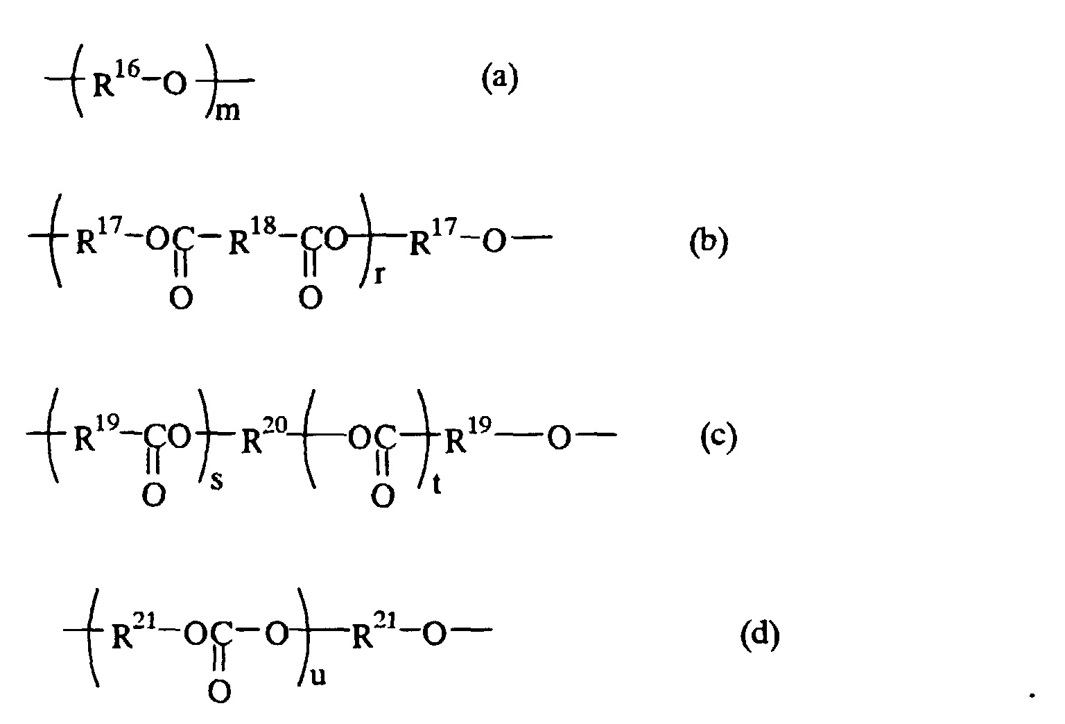
In formulae (a) through (d), R16 through R21 may be the same or
different and are each a C1-C20, preferably C2-C12 divalent hydrocarbon
residue. R21 is particularly preferably a C2-C6 divalent hydrocarbon
residue. R16 through R21 are preferably straight or branched alkylene
groups among which methylene, ethylene, trimethylene, tetramethylene,
pentamethylene, hexamethylene and propylene groups are preferred for R18,
and ethylene and propylene groups are preferred for R16, R17 and R19
through R21. The letter "m" in formula (a) is an integer of 2-300,
preferably 10-200, the letter "r" is an integer of 1-300, preferably 2-200,
the letter "s" is an integer of 1-200, preferably 2-100, the letter "t" is an
integer of 1-200, preferably 2-100 and the letter "u" is an integer of 1-300,
preferably 10-200.
Each unit represented by formulae (a) through (d) may be a
copolymer of the same or different units. Namely, if there exist a plurality
of groups of each R16 through R21, groups of each R16, R17, R18 ,R19, R20 and
R21 may be the same or different. Preferred examples of such copolymers
include copolymers of ethylene oxide and copolymers of propylene oxide.
An urethaneacrylate of formula (II) has a molecular weight in the
range of 2,500-30,000, preferably 3,000-20,000.
The urethaneacrylate has preferably 2-6, more preferably 2-4
polymerization functional groups per molecule.
The urethaneacrylate may be prepared by any suitable conventional
method.
An organic polar solvent (organic nonaqueous solvent) is added in
an amount of 100-200, preferably 200-900 weight parts per 100 parts of
the urethaneacrylate. Too less amount of the addition of the organic polar
solvent would result in insufficient ion conductivity, while too much
amount of the addition would cause reduced mechanical strength.
No particular limitation is imposed on a supporting electrolyte as
long as it is not obstructive in achievement of the purpose of the invention.
Preferred are those already exemplified above. The supporting electrolyte
should be added in an amount of 0.1-30, preferably 1-20 weight percent of
the organic polar solvent.
Composition (A) is obtained by solidifying the above-described
essential components, namely, the above-described urethaneacrylate,
organic nonaqueous solvent and supporting electrolyte. If necessary, any
suitable optional components may be added to Composition (A) as long as
they are not obstructive to the achievement of the purpose of the invention.
Such components may be crosslinkers and photo- or thermal polymerization
initiators.
The solid polymeric electrolyte of the first example may be
inserted between a pair of electrically conductive substrates disposed,
facing each other by injecting Composition (A) into a selected space
between the substrates in a conventional manner and curing the same. The
term "curing" used herein designates a state where polymerizing or
crosslinking component is brought to be cured with the progress of
polymerization (polycondensation) or crosslinking and thus the composition
does not flow at room temperature. The composition thus cured has the
basic structure in the form of network.
A second example of the polymeric solid electrolyte is obtained by
solidifying a composition (hereinafter referred to as Composition (B))
comprising an organic polar solvent, a supporting electrolyte, a
monofunctional acryloyle-modified polyalkylene oxide of formula (18)
below and a polyfunctional acryloyle-modified polyalkylene oxide of
formula (19) or (20) below.
Formula (18) is represented by
 wherein R22, R23, R24 and R25 may be the same or different and are each
hydrogen and an alkyl group having 1-5 carbon atoms and n is an integer
of greater than 1.
wherein R22, R23, R24 and R25 may be the same or different and are each
hydrogen and an alkyl group having 1-5 carbon atoms and n is an integer
of greater than 1.
Specific examples of the alkyl group include methyl, ethyl, i-propyl,
n-propyl, n-butyl, t-butyl and n-pentyl. Preferred for R22, R23 and R24 are
hydrogen and a methyl group. Preferred for R25 are hydrogen, methyl and
ethyl groups.
The letter "n'" in formula (18) is an integer of greater than 1,
usually from 1 to 100, preferably from 2 to 50 and more preferably from 2
to 30.
Specific examples of the compound represented by formula (18) are
those having 1-100, preferably 2-50 and more preferably 1-20 oxyalkylene
units, such as methoxypolyethylene glycol methacrylate,
methoxypolypropylene glycol methacrylate, ethoxypolyethylene glycol
methacrylate, ethoxypolypropylene glycol methacrylate,
methoxypolyethylene glycol acrylate, methoxypolypropylene glycol
acrylate, ethoxypolyethylene glycol acrylate, ethoxypolypropylene glycol
acrylate and mixtures thereof.
If n is greater than 2, the compound may be those having different
oxyalkylene units, that is, copolymerized oxyalkylene units which for
instance have 1-50, preferably 1-20 oxyethylene units and 1-50, preferably
1-20 oxypropylene units. Specific examples of such compounds are
(ethylene · propylene) glycol methacrylate, ethoxypoly ( ethylene ·
propylene) glycol methacrylate, methoxypoly (ethylene · propylene) glycol
methacrylate, methoxypoly (ethylene · propylene) glycol acrylate,
ethoxypoly methoxypoly (ethylene · propylene) glycol acrylate and mixtures
thereof.
The polyfunctional acryloyl-modified polyalkylene oxide may be a
bifunctional acryloyl-modified polyalkylene oxide represented by the
formula
 wherein R26, R27, R28 and R29 are each hydrogen and a C1-C5 alkyl group
and m' is an integer of greater than 1; or a polyfunctional acryloyl-modified
polyalkylene oxide having more than three functional groups represented by
the formula
wherein R26, R27, R28 and R29 are each hydrogen and a C1-C5 alkyl group
and m' is an integer of greater than 1; or a polyfunctional acryloyl-modified
polyalkylene oxide having more than three functional groups represented by
the formula
 wherein R30, R31 and R32 are each hydrogen and a C1-C5 alkyl group, p' is
an integer of greater than 1, q' is an integer from 2 to 4 and L is a
connecting group of valence indicated by q'.
wherein R30, R31 and R32 are each hydrogen and a C1-C5 alkyl group, p' is
an integer of greater than 1, q' is an integer from 2 to 4 and L is a
connecting group of valence indicated by q'.
In formula (19), R26, R27, R28 and R29 are each hydrogen or a C1-C5
alkyl group, such as methyl, ethyl, i-propyl, n-propyl, n-butyl,
t-butyl, t-butyl and n-pentyl groups among which preferred are hydrogen
and methyl. The letter "m'" in formula (19) is an integer of greater than 1,
usually from 1 to 100, preferably from 2 to 50, and more preferably from 2
to 30. Preferred examples of compounds of formula (19) are those having
1-100, preferably 2-50, more preferably 1-20 oxyalkylene units such as
polyethylene glycol diacrylate, polypropylene glycol dimethacrylate,
polyethylene glycol diacrylate, polypropylene glycol dimethacrylate and
mixtures thereof.
If m is greater than 2, the compound of formula (19) may be those
having different oxyalkylene units, that is, polymerized oxyalkylene unit
having 1 - 50, preferably 1-20 oxyethylene units and 1-50, preferably 1-20
oxypropylene units, such as poly(ethylene · propylene)glycol dimethacrylate,
poly(ethylene · propylene)glycol diacrylate and mixtures thereof.
In formula (20), R30, R31 and R32 are each hydrogen or a C1-C5 alkyl
group, such as methyl, ethyl, i-propyl, n-propyl, n-butyl, t-butyl and n-pentyl.
Particularly preferred for R30, R31 and R32 are hydrogen and a
methyl group.
The letter "p" is an integer of greater than 1, usually from 1 to 100,
preferably from 2 to 50 and more preferably from 2 to 30.
The letter "q" indicates the number of connecting group "L" and is
an integer from 2 to 4.
Connecting group "L" is a divalent, trivalent or quatravalent
hydrocarbon group having 1-30, preferably 1-20 carbon atoms.
Such divalent hydrocarbon groups may be alkylene, arylene,
arylalkylene, alkylarylene and hydrocarbon groups having those groups as
the base skeleton. Specific examples of such hydrocarbon groups are
those represented by the following formulae

Such trivalent hydrocarbon groups may be alkyltryl, aryltryl,
arylalkyltryl, alkylaryltryl and hydrocarbon groups having those groups as a
base skeleton. Specific examples of such hydrocarbon groups are those
represented by the following formulae :
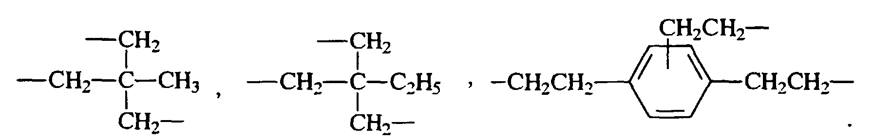 Such quatravalent hydrocarbon groups may be alkyltetraryl, aryltetraryl,
arylalkyltetraryl, alkylaryltetraryl and hydrocarbon groups having those
groups as the base skelton. Specific examples of such hydrocarbon groups
are those represented by the following formulae :
Such quatravalent hydrocarbon groups may be alkyltetraryl, aryltetraryl,
arylalkyltetraryl, alkylaryltetraryl and hydrocarbon groups having those
groups as the base skelton. Specific examples of such hydrocarbon groups
are those represented by the following formulae :

Specific examples of the compounds of formula (20) are those
having 1-100, preferably 1-50, more preferably 1-20 of an oxyalkylene
units such as trimethylolpropanetri(polyethylene glycol acrylate),
trimethylolpropanetri (polyethylene glycol methaacrylate),
trimethylolpropanetri (polypropylene glycol acrylate),
trimethylolpropanetri (polypropylene glycol methaacrylate),
tetramethylolmethanetetra(polyethylene glycol acrylate),
tetramethylolmethanetetra (polyethylene glycol methaacrylate),
tetramethylolmethanetetra(polypropylene glycol acrylate),
tetramethylolmethanetetra(polypropylene glycol methaacrylate),
2,2-bis[4-(acr yloxypolyethoxy)phenyl]propane,
2,2-bis[4-(methaacryloxypolyethox y)phenyl]propane,
2,2-bis[4-(acryloxypolyisopropoxy)phenyl]proparae,
2,2-bis[4-(methaacryloxypolyisopropoxy)phenyl]propane and mixtures
thereof.
If p is more than 2, the compounds of formula (20) may be those
having different oxyalkylene units, that is, polymerized oxyalkylene units
having 1-50, preferably 1-20 of oxyethylene units and 1-50, preferably 1-20
oxypropylene units. Specific examples of such compounds include
trimethylolpropanetri(poly(ethylene · propylene)glycol acrylate),
trimethylolpropanetri(poly(ethylene · propylene)glycol methaacrylate),
tetramethylolmethanetetra(poly(ethylene · propylene)glycol acrylate),
tetramethylolmethanetetra(poly(ethylene · propylene)glycol acrylate) and
mixtures thereof.
Needless to mention, there may be used a combination of a
difunctional acryloyl-modified polyalkyleneoxide of formula (19) and a
polyfunctional acryloyl-modified polyalkyleneoxide of formula (20).
When these compounds are used in combination, the weight ratio of a
compound of formula (19) to that of formula (20) is in the range from
0.01/99.9 to 99.9/0.01, preferably from 1/99 to 99/1 and more preferably
from 20/80 to 80/20. The weight ratio of a compound of formula (18) to a
polyfunctional acryloyl-modified polyalkyleneoxide is in the range of
usually from 1/0.001 to 1/1, preferably from 1/0.05 to 1/0.5.
The above-described organic polar solvent should be added in an
amount of 50-800, preferably 100-500 weight percent based on the total
weight of the compound of formula (18) and the polyfunctional acryloyl-modified
polyalkyleneoxide.
The above-described supporting electrolyte should be added in an
amount of 1-30, preferably 3-20 weight percent based on the total weight of
the compound of formula (18), the polyfunctional acryloyl-modified
polyalkyleneoxide and the organic polar solvent.
If necessary, another optional components other than the above-described
components may be added to Composition (B) as long as they do
not give adverse effect on the inventive electrochromic mirror. Although
not restricted, such components may be photopolymerization initiators or
thermal polymerization initiators. These initiators should be added in an
amount of 0.005-5, preferably 0.01-3 weight percent based on the total
weight of the compound of formula (18) and the polyfunctional acryloyl-modified
polyalkylene oxide.
The polymeric solid electrolyte described above as a second
example may be inserted between a pair of electrically conductive
substrates facing each other by injecting Composition (B) into a selected
site therebetween by any suitable method. The "curing" used herein
designates a state where a polymerizable or crosslinkable component such
as monofunctional or polyfunctional acryloyl-modified polyalkyleneoxide
is brought to be cured with the progress of polymerization or crosslinking
and hence the composition entirely stays unfluidized. In this case, the
monofunctional or polyfunctional acryloyl-modified polyalkyleneoxide has
the basic structure in the form of networks.
Needless to mention, ion conductive materials other than those as
described above are also eligible.
Next, an electrochromic color developing layer constituting the
inventive electrochromic mirror is described. The electrochromic color
developing layer used in the present invention is characterized in that it
contains (A) a compound having a viologen structure represented by the
formula (hereinafter referred to as Compound A)
 and (B) 4,4'-dipyridyl (hereinafter referred to as Compound B1) or a 1-substituted
4,4'-dipyridinium salt (hereinafter referred to as Compound B2)
represented by the formula
and (B) 4,4'-dipyridyl (hereinafter referred to as Compound B1) or a 1-substituted
4,4'-dipyridinium salt (hereinafter referred to as Compound B2)
represented by the formula
 Compounds B1 and B2 are hereunder generically referred to as Compound
B.
Compounds B1 and B2 are hereunder generically referred to as Compound
B.
First, Compound (A) is described.
Compound (A) has a viologen structure represented by formula (1)
above.
In formula (1), X- and Y- are each a counter anion and may be the
same or different and an anion selected from the group consisting of a
halogen anion, ClO4 -, BF4 -, PF6 -, CH3COO- and CH3(C6H4)SO3 -. The
halogen anion may be F-, Cl-, Br- and I-.
No limitation is imposed on the compound having a viologen
structure as long as it possesses electrochromic properties. Such a
compound is exemplified by high molecular weight compounds and low
molecular weight compounds. Such high molecular weight compounds
may be those having a viologen structural unit or a unit containing a
viologen structure as a repeating unit or those having at their terminal ends
a viologen structural unit as well as those having molecular chains part of
which is substituted with a group having a viologen structure. Such low
molecular weight compounds may be those having a viologen structure.
The high molecular weight compounds having repeating units may be those
of which side or main chain is formed by viologen structural units. There
is no restriction to the repeating units forming the main chains of high
molecular weight compounds if the side chains are formed by viologen
structural units. Such repeating units forming the main chain may be
hydrocarbon units, oxygen-containing units, nitrogen-containing units,
polysiloxane units and copolymerized units thereof.
The compound having a viologen structure may be a polymer or
copolymer represented by the formula

The letter "m" indicates an integer of more than 1, preferably from 1
to 1,000, and the letter "n" indicates an integer of more than 0, preferably
from 0 to 1,000. R33 is a C1-C20, preferably C1-C12 divalent hydrocarbon
residue or merely indicates the bond of the viologen group directly to a
polymer chain not through the hydrocarbon residue, namely covalently
bond. Specific examples of hydrocarbon groups include aliphatic
hydrocarbon groups such as methylene, ethylene, propylene, tetramethylene,
pentamethylene and hexamethylene and aromatic hydrocarbon groups such
as phenylene, biphenylene and benzylidene. Specific examples of
oxygen-containing hydrocarbon groups include aliphatic alkoxylene groups
such as -OCH2-, -OCH2CH2- and -OCH2CH2CH2-, aliphatic
dialkoxylene groups such as -OCH2CH2O- and -OCH2CH2CH2O-,
aromatic aryloxy groups such as -O(C6H4)- and -OCH2(C6H4)- and
aromatic diaryloxy groups such as -O(C6H4)O and -OCH2(C6H4)O-.
X- and Y- each indicate a counter anion which is a monovalent
anion, with respect to viologen and may be the same or different. X- and
Y- may be a halogen anion such as F-, Cl-, Br- and I-, ClO4 -, BF4 -, PF6 -,
CH3COO- and CH3(C6H4)SO3 -.
R34, R35 and R36 are each a C1-C20, preferably C1-C12 hydrocarbon
group and a hetero atom-containing substituent and a halogen atom.
Preferred hydrocarbon groups for R34, R35 and R36 are alkyl groups such as
methyl, ethyl, propyl and hexyl and an aryl group such as phenyl, tolyl,
benzyl and naphzyl. Preferred hetero atom-containing substituents are a
C1-C20, preferably C1-C12 oxygen-containing hydrocarbon group, amide,
amino and cyano groups. Such oxygen-containing hydrocarbon groups
include an alkoxyl group such as methoxy and ethoxy an aryloxy group such
as phenoxy and triloxy, a carboxyl group and a residual carboxylic acid
ester.
In the case where the compound of formula (21) is a copolymer, the
copolymerization pattern of the repeating units may be that of block-,
random- or alternate copolymerization.
The compound having a viologen structure may also be a polymer or
copolymer represented by the formula

In formula (22), m, n and X- and Y- are the same as defined in
formula (21) and n is preferably 0. R37 and R39 may be the same or
different and are each the same as those as defined with respect to R33 in
formula (21) and R38 and R40 may the same or different and each are the
same as those as defined with respect to R34 in formula (21).
In the case where a compound of formula (22) is a copolymer, the
copolymerization pattern of the repeating units may be that of block,
random or alternate polymerization.
Moreover, the compound having a viologen structure may also be a
polymer or copolymer represented by the formula
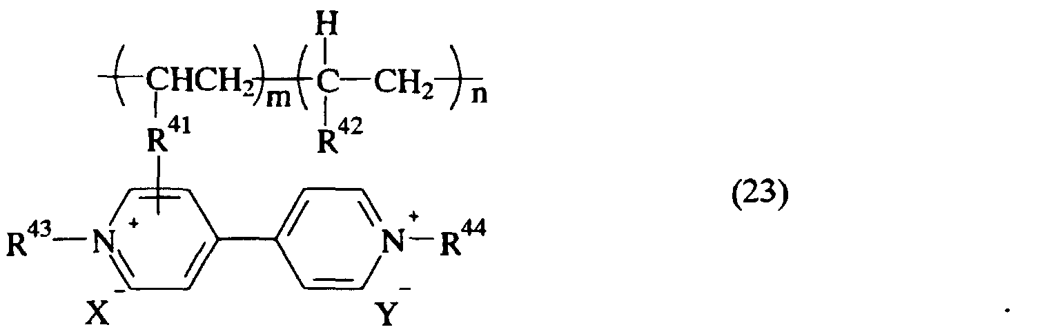
In formula (23), m, n and X- and Y- are the same as those as
defined in formula (21) and n is preferably 0. R41 is the same as those as
defined with respect to R33 in formula (21) and R42, R43 and R44 may be the
same or different and each are the same as those as defined with respect to
R34 in formula (21).
In the case where the compound of formula (23) is a copolymer, the
copolymerization pattern of the repeating units may be that of block,
random or alternate of polymerization.
Furthermore, the compound having a viologen structure may be a
copolymer represented by the formula

In formula (24), p is an integer of more than 0, preferably from 0 to
20, q is an integer of 0-1,000 and R45 is the same as those as defined with
respect to R33 in formula (21).
Further alternatively, the compound having a viologen structure
may also be a polymer or copolymer of the formula

In formula (25), R is a C1-C10 alkyl group, r is an integer of more
than 1, preferably from 1 to 1,000, R46 is the same as those as defined with
respect to R33 in formula (21) and R47 is the same as those as defined with
respect to R33 in formula (21).
Typical examples of the compound having a viologen structure used
for the present invention have been exemplified by compounds of formulae
(21) through (25). Specific examples of compounds which are included
within the range of these formulae and which are not included within the
range of these formulae but eligible for the invention are given below. Pr
in the following formulae indicates a propyl group.


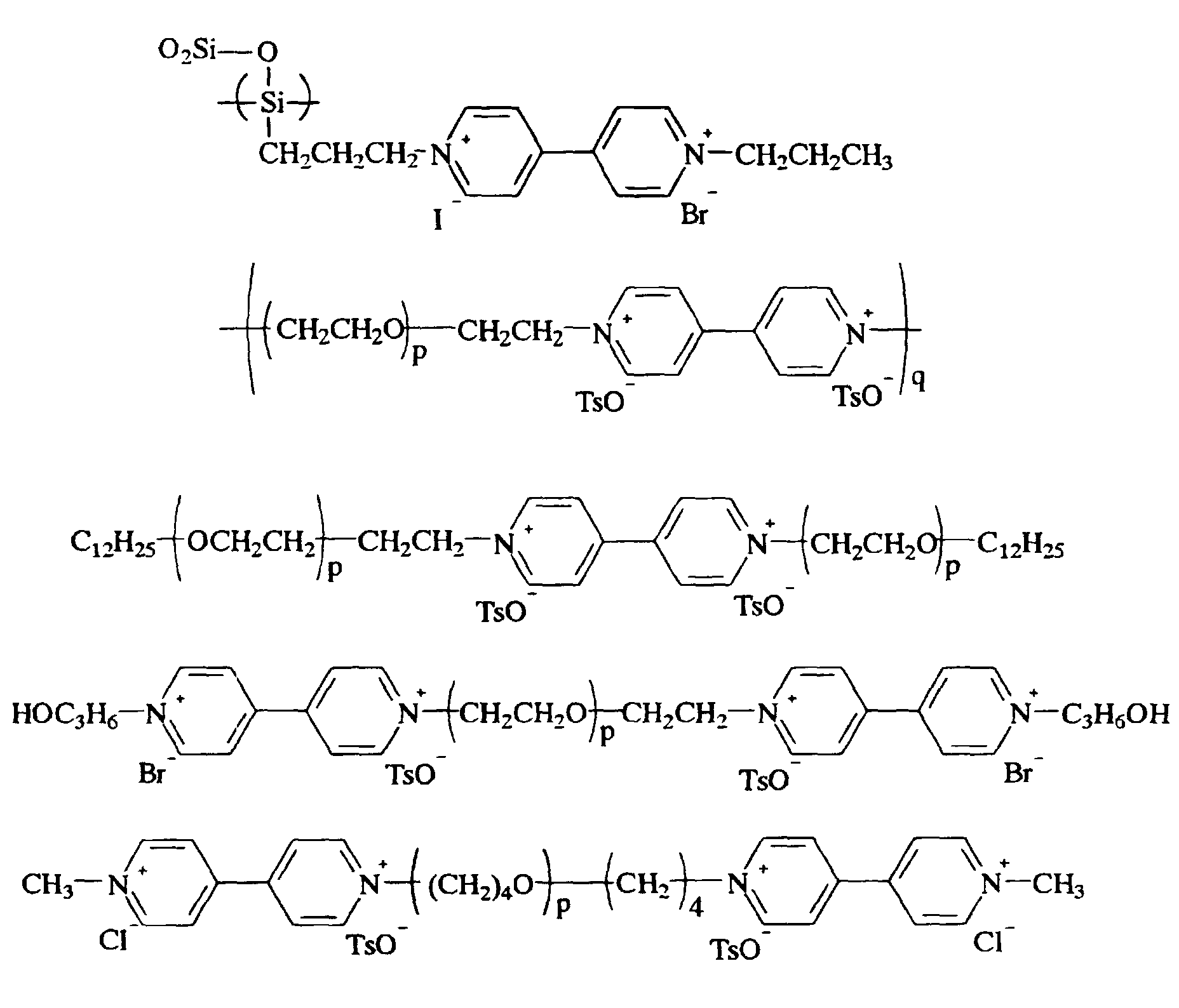
Next, Compound B is described.
As described above, Compound B is encompassed by 4,4'-dipyridyl
(Compound B1)and a 1-substituted 4,4'-dipyridinium salt(Compound B2)
represented by formula (2).
The substitution structure of 1-substituted 4,4'-dipyridinium salt
may be in the form of mixtures.
No particular limitation is imposed on Compound B2 as long as it
possesses electrochromic properties when used in combination with
Compound A. Compound B2 may thus be high molecular weight or low
molecular weight compounds. Such high molecular weight compounds
may be those having repeating units containing a 1-substituted-4,4'-dipyridinium
salt or those having at their terminal ends a 1-substituted-4,4'-dipyridinium
salt. Such low weight molecular weight compounds
may be those having hydrogen or lower molecular weight substituent at the
terminal end of a 1-substituted-4,4'-dipyridinium salt.
The high molecular weight compounds having repeating units may
be those of which side or main chains are formed of 1-substituted-4,4'-dipyridinium
salts. There is no restriction to the repeating units forming
the main chains of high molecular weight compounds if 1-substituted-4,4'-dipyridinium
salts forms the side chains. Such repeating units may be
hydrocarbon units, oxygen-containing units, nitrogen-containing units,
polysiloxane units and copolymerized units thereof.
Compound B2 may be a polymer or copolymer represented by the
formula

The letter "m" indicates an integer of more than 1, preferably from 1
to 1,000, and the letter "n" indicates an integer of more than 0, preferably
from 0 to 1,000. R48 is a C1-C20, preferably C1-C12 divalent hydrocarbon
residue or merely indicates the bond of the viologen group directly to a
polymer chain not through the hydrocarbon residue, namely covalently
bond. Specific examples of hydrocarbon groups include aliphatic
hydrocarbon groups such as methylene, ethylene, propylene, tetramethylene,
pentamethylene and hexamethylene and aromatic hydrocarbon groups such
as phenylene, biphenylene and benzylidene. Specific examples of
oxygen-containing hydrocarbon groups include aliphatic alkoxylene groups
such as -OCH2-, -OCH2CH2- and -OCH2CH2CH2-, aliphatic
dialkoxylene groups such as -OCH2CH2O- and -OCH2CH2CH2O-,
aromatic aryloxy groups such as -O(C6H4)- and -OCH2(C6H4)- and
aromatic diaryloxy groups such as -O(C6H4)O and -OCH2(C6H4)O-.
X- indicates a counter anion which is a monovalent anion, with
respect to viologen and may be same or different. X- may be a halogen
anion such as F-, Cl-, Br- and I-, ClO4 -, BF4 -, PF6 -, CH3COO- and
CH3(C6H4)SO3 -.
R49 and R50 are each a C1-C20, preferably C1-C12 hydrocarbon group
and a hetero atom-containing substituent and a halogen atom. Preferred
hydrocarbon groups for R49 and R50 are alkyl groups such as methyl, ethyl,
propyl and hexyl and an aryl group such as phenyl, tolyl, benzyl and
naphtyl. Preferred hetero atom-containing substituents are a C1-C20,
preferably C1-C12 oxygen-containing hydrocarbon group, amide, amino and
cyano groups. Such oxygen-containing hydrocarbon groups include an
alkoxyl group such as methoxy and ethoxy an aryloxy group such as
phenoxy and triloxy, a carboxyl group and a residual carboxylic acid ester.
In the case where the compound of formula (26) is a copolymer, the
copolymerization pattern of the repeating units may be that of block-,
random- or alternate copolymerization.
Alternatively, Compound B2 may be a polymer or copolymer
represented by the formula

In formula (27), m, n and X- are the same as defined in formula
(26) and n is preferably 0. R51 is the same as defined with respect to R48 in
formula (48). R52 and R53 may be the same or different and are each the
same as those as defined with respect to R49 in formula (26).
In formula (27) R51 is allowed to be bonded to any position of the
pyridine ring to which R53 bonds but may be bonded to the pyridine ring
free of substituents.
In the case where a compound of formula (27) is a copolymer, the
copolymerization pattern of the repeating units may be that of block-,
random- or alternate copolymerization.
Furthermore, Compound B2 may be a polymer or copolymer
represented by the formula

In formula (28), R is a C1-C10 alkyl group, r is an integer of
greater than 1, preferably from 1 to 1,000. R54 is the same as those defined
with respect to R48 in formula (26).
Typical examples of eligible compounds having the above-described
1-substituted dipyridine structure for the present invention have been
described in reference with formula (26) through (28). Specific examples
of compounds encompassed by these formulae and compounds not
encompassed thereby but eligible for the invention are as follows:


Compounds A, B1 and B2 can be produced by any suitable known
method.
As described above, the electrochromic layer of the present
invention contains Compound A and Compound B and is typically formed
from a composition comprising Compound A and Compound B. Such a
composition may be produced by a method in which Compounds A and B
are produced separately from each other and then mixed together.
Alternatively, the composition may be produced by reacting precursors or
materials inducing Compounds A and B, respectively under desired
conditions. From an industrial point of view, the latter method is preferred.
For example, Compound B1 is a commercial product and thus easily
available. Therefore, Compound B1 used as a starting material is reacted
with a polymerizing or non-polymerizing halogenated compound of more
than equimolecular amounts, usually 1-3 times greater mole of Compound
B1 (4,4'-dipyridyl) in an inactive solvent i.e. an organic solvent which is
not reactive with 4,4'-dipyridyl and free of halogen, such as alcohols,
pentane, hexane, cyclohexane, diethylether, acetone, benzene, toluene,
ethyl acetate, acetonitrile, dimethyl formamide and dimethyl sulfoxide, and
then heated with stirring for a certain period of time, followed by vacuum-distillation
of the solvent and the unreacted halogenated compound so as to
obtain a mixture of Compound A, Compound B2 and Compound B1
remaining unreacted.
Although recrystallization or column separation is generally
employed for the purification of viologen, such an operation may be
omitted and it is sufficient only to remove the halogenated compound used
as a starting material and solvent used for reaction.
The molar composition ratio of Compound A to Compound B is
within the range of 1 : 99-99.9 : 0.1, preferably 80 : 20-99.9 : 0.1, and
more preferably 95 : 5-99 : 1.
The electrochromic layer of the present invention contains
essentially Compound A and Compound B but is almost entirely composed
of only Compound A and Compound B. The electrochromic layer is
obtained by forming these compounds into a film or layer, over the above-mentioned
conductive substrate. No particular limitation is imposed on a
method of forming the film or layer. A method is employed in which to
apply and dry a solution obtained by dissolving Compounds A and B in a
solvent. Alternatively, a method is employed in which Compounds A and
B are cast over the above-mentioned conductive substrate and then cooled
after being melted by heating. The former method is particularly
preferred.
No particular limitation is imposed on a solvent used in the former
method as long as it is volatile. Examples of such solvents are dimethyl
sulfoxide, dimethyl acetamide, dimethyl formamide, N-methyl pyrrolidone,
γ -valerolactone, dimethoxyethane, acetnitrile, propionenitrile,
tetrahydrofuran, dioxane, methanol, ethanol, propanol, chloroform, toluene,
benzene, nitrobenzene and dioxolan.
The applying method may be cast coating, spin coating, dip coating,
spray coating, blade coating and flow coating. Drying may also be
conducted by any conventional method.
The electrochromic color developing layer is easily oxidized or
reduced by being applied with a voltage and thus colored or discolored.
The electrochromic color developing layer is generally 0.01 to 50
µm, preferably 0.1-20 µm.
If necessary, another compounds promoting color developing may
be used in combination with Compounds A and B.
As described above, an electrochromic mirror according to the
present invention comprises a reflective conductive substrate, a transparent
conductive substrate, an ion conductive layer inserted therebetween and an
electrochromic color developing layer disposed between the ion conductive
layer and at least either one of the two conductive substrates, wherein the
electrochromic color developing layer contains Compounds A and B. The
description is now made to the basic structure of the electrochromic mirror.
Figs. 1 through 4 exemplarily show the structures of the inventive
electrochromic mirror.
The electrochromic mirror shown in Fig. 1 is constituted by a first
laminate formed by a transparent conductive substrate including a
transparent substrate (1), a transparent electrode layer (2) formed on one
surface of the substrate and an electrochromic color developing layer (3)
formed on the electrode layer (2); a second laminate formed by a reflective
conductive substrate including a transparent or opaque substrate (7) and a
reflective electrode layer (6) formed thereon, and an ion conductive layer
disposed in sandwich relation in the space properly provided between the
first and second laminates which are placed so that the electrochromic color
developing layer (3) and the reflective substrate (6) face each other.
The another example of the electrochromic mirror shown in Fig. 2 is
constituted by a first laminate formed by a transparent conductive substrate
including a transparent substrate (1) and a transparent electrode layer (2)
formed on one surface of the substrate and an electrochromic color
developing layer (3) formed on the electrode layer (2); a second laminate
formed by a transparent substrate (1) having a transparent electrode layer
(2) formed on one surface of the substrate and a reflective layer (8) formed
on the other surface; and an ion conductive material (4) disposed in
sandwich relation in the space properly provided between the first and
second laminates which are placed so that the electrochromic color
developing layer (3) and the transparent electrode layer of the second
laminate (2) face each other.
The electrochromic mirror shown in Fig. 3 is constituted by a first
laminate formed by a transparent conductive substrate including a
transparent substrate (1) and a transparent electrode layer (2) formed on one
surface of the substrate; a second laminate formed by a transparent or
opaque substrate (7) having a reflective electrode layer (6) formed thereon
and an electrochromic color developing layer (3) formed on the reflective
electrode layer (6); and an ion conductive material (4) disposed in sandwich
relation in the space properly provided between the first and second
laminates which are placed so that the transparent electrode layer and the
electrochromic color developing layer (3) face each other.
Fig. 4 shows another example of the inventive electrochromic mirror
which is constituted by a first laminate formed by a transparent conductive
substrate including a transparent substrate (1) and a transparent electrode
layer (2) formed thereon; a second laminate formed by a reflective
conductive substrate including a transparent substrate (1), a transparent
electrode layer (2) formed on one surface thereof and an electrochromic
color developing layer (3) formed thereon and a reflective layer (8) formed
on the other surface of the substrate (1); and an ion conductive material (14)
disposed in sandwich relation in the space properly provided between the
first and second laminates which are placed so that the transparent electrode
layer (2) of the first laminate and the electrochromic chromogenic layer (3)
of the second laminate face each other.
Needless to mention, each of the electrochromic mirrors shown in
Fig. 1 thorough 4 can be colored or bleached by electrochromic
phenomenon brought by an electric voltage applied over each electrode.
An electric voltage can be applied by any conventional method.
No particular limitation is imposed on a method for forming each of
the layers or films of the inventive electrochromic mirror. Each of the
layers or films can be formed in accordance with the methods described
above. Taking an example from the electrochromic mirror shown in Fig. 1,
the transparent electrode layer (2) is formed on the transparent substrate (1)
in the above-described manner and then the electrochromic color
developing layer (3) is formed on the electrode layer (2) thus formed
thereby obtaining a laminate (referred to as Laminate A). Separately, a
laminate (referred to as Laminate B) is obtained by forming a reflective
electrode layer (6) on a substrate (7) in accordance with the procedure
described above. Laminates A and B are placed, facing each other and
spaced 1-1,000 µm apart and sealed at their edges with a sealant (5),
leaving a portion used for an inlet, thereby forming a empty cell. An ion
conductive material or the precursor thereof is injected from the inlet into
the cell in a manner described above so as to form the layer of the ion
conductive material thereby producing an electrochromic mirror.
When Laminates A and B are placed, facing each other, a spacer
may be inserted therebetween so as to provide the space retained constantly.
No particular limitation is imposed on such a spacer. There may be used a
spacer in the form of beads or a sheet. The spacer may be inserted
between the conductive substrates facing each other or provided by forming
the protrusions of an insulate material of the electrode on an electric
conductive substrate.
The ion conductive material layer (4) may be formed by curing the
precursor thereof after being injected into the space between the conductive
substrates facing each other and the same. No particular limitation is
imposed on a method for curing the precursor. Therefore, the precursor
may be cured by using light or heating or by mixing a reactive liquid which
cures with the progress of time with the precursor before injection thereof.
The inlet of the cell may be sealed in a suitable manner after completion of
the injection of the precursor of the ion conductive material.
Alternatively, a transparent electrode layer (2), an electrochromic
color developing layer (3) and an ion conductive layer (4) are formed one
after another in the order mentioned in the above-described manner thereby
forming a laminate (referred to as Laminate A'). Separately from this, a
laminate (referred to as Laminate B') is obtained by forming a reflective
electrically conductive layer (6) on a substrate (7). Laminates A' and B'
are placed, facing each other with a space of 1-1000 µm so that the ion
conductive material layer of Laminate A' contacts the reflective electrically
conductive of Laminate B' and then sealed at their edges with a sealant (5).
The electrochromic mirror shown in Fig. 2 may be obtained by
forming a transparent electrode layer (2) on one surface of a transparent
substrate (1) and a reflective layer on the other surface and then following
the same procedure as described with respect to the electrochromic mirror
shown in Fig. 1.
The electrochromic mirrors shown in Figs. 3 and 4 can be produced
by taking the same procedure as described with respect to those shown in
Figs. 1 and 2.
Although Figs. 1 through 4 illustrate the typical examples of the
structure of the inventive electrochromic mirror, it is not limited to these
structures and thus may contain additional components. Such additional
components may be an ultraviolet blocking layer such as an ultraviolet
reflective layer and an ultraviolet absorbing layer and an overcoat layer
provided to protect the mirror entirely or the surface of each of the films or
layers. The ultraviolet blocking layer is preferably disposed on the outer
side of a transparent substrate (1) or on a transparent electrode layer formed
on the transparent substrate. The overcoat layer is preferably disposed on
the outer side of a transparent substrate (1) or the outer side of a reflective
layer (8).
The electrochromic device has been described above in reference to
an electrochromic mirror. Needless to mention, light controlling element
and display element can be obtained by replacing a reflective conductive
substrate with a transparent or non-reflective conductive substrate.
Because the electrochromic device according to the present
invention has an electrochromic layer containing specific compounds, it can
be easily manufactured at low cost and has an excellent feature that
coloration density can be adjusted easily by changing the specifications of
the compounds. It is also possible to produce a large-sized mirror
enhanced in safety because of availability of a solid electrolyte as an ion
conductive material layer which is free from scattering.
Furthermore, the present invention is contributive to the industry
because a viologen compound can be used even if the viologen is not
sufficiently purified. Moreover, the present invention can provide an
electrochromic device of which viologen compound and electrolyte are hard
to be deteriorated even if an acid present in a slight amount in a device
(mirror) is mixed with the viologen compound or the electrolyte. As a
result of this, the electrochromic device is prevented from being shortened
in the lifetime of the coloration and bleach functions and thus can perform
its characteristics in a stable manner over an extended period of time.
For the reasons described above, the electrochromic device
according to the present invention can be applied particularly suitably to
antidazzle mirrors for vehicles such as automobiles and decorative mirrors.
Alternatively, the inventive electrochromic device is applicable to various
types of display and light controlling device as well.
The present invention will now be described in further detail with
reference to Examples, which are given only by way of illustration and are
not intended for limiting the invention.
After 4,4'-dipyridyl and 1-bromopropane in an equimolar ratio were
reacted by heating in acetone with refluxing, an acetone solvent and
unreacted 1-brompropane was distilled out thereby obtaining a solid
substance containing 4-(4'-dipyridyl) pyridinium. The solid substance
was reacted with 1,2-dibromoethane at 100°C in dimethyl formamide
thereby obtaining a viologen mixture containing 1-propyl-1'-bromoethyl-4,4'-dipyridinium
bromide. HBr was removed from the mixture with a
NaOH solution thereby obtaining a viologen mixture monomer containing
1-propyl-1'-vinyl-4,4'-dipyridinium bromide.
The resulting monomer was subjected to bulk polymerization using
di-t-butylperoxide as a catalyst at 130°C thereby obtaining a solid
substance (referred to as Solid A) containing a polymer with a structure
below as the main component (average molecular weight : about 4,000, n :
about 10).

The polymer thus obtained was subjected to Soxlet extraction using
methanol. The eluted product obtained by removing the methanol was
evaluated with liquid chromatography and 1H-NMR and found to be 4,4'-dipyridyl
the amount of which was about 0.1% of the 4,4'-dipyridyl which
was subjected to the initial reaction.
The remaining polymer was then subjected to neutralization
titration reaction using an HBr aqueous solution in water and HBr in an
amount of 3 % by molar ratio of the initial 4,4'-dipyridyl was consumed.
Namely, it was confirmed that about 3 % by mole of 1-substituted
dipyridinium salt was present in the polymer.
Solid A produced in (1) above was dissolved in nitrobenzene to
make it a solution containing 10 % by weight of Solid A. The solution was
applied onto the surface on which a platinum film (reflective electrode) was
formed, of a substrate and then heated on a hot plate to remove
nitrobenzene so as to form the thin film of the electrochromic compound
with a thickness of 5µm thereby obtaining a reflective conductive substrate
with an electrochromic layer (designated hereinafter as Laminate A).
A glass substrate with an electrically conductive layer of palladium
was used as a transparent conductive substrate (designated hereinafter as
Laminate B). An epoxy-based resin was applied in the form of lines on the
edges other than a portion forming an inlet of an electrolyte precursor
solution, of Laminate B. Laminate A was superposed on Laminate B such
that the electrochromic layer faced the transparent electrode layer while
being pressed so as to cure the adhesive thereby to provide an empty cell
with an inlet.
On the other hand, a homogenous solution was obtained by adding
0.4 g of lithium perchlorate to a mixed solution of 1.0 g of
methoxypolyethylene glycol monomethacrylate (oxyethylene unit number :
4) manufactured by SHIN NAKAMURA CHEMICAL CO., LTD. under the
trade name of ME04, 0.02 g of polyethylene glycol dimethacrylate
(oxyethylene unit number: 9) manufactured by SHIN NAKAMURA
CHEMICAL CO., LTD. under the trade name of 9G and 4.0 g of γ-butylolactone.
To the homogenous solution was added 0.02 g of
1-(4-isopropylphenyl)-2-hydroxy-2-methylpropane-1-on manufactured by
Merk Co,. Ltd., under the name of "Darocure-1116" as a
photopolymerization initiator in a dark room thereby obtaining an
electrolyte precursor. The electrolyte precursor was then injected into the
cell obtained above through the inlet after being deaerated.
After the injection port was sealed with an epoxy sealant, the
electrolyte precursor in the cell was cured by exposing the side of the
transparent substrate of the cell to fluorescent light so as to form a solid
electrolyte thereby obtaining an all solid type electrochromic mirror of the
structure as shown in Fig. 3.
The mirror when assembled was not colored and had a reflectance
of about 85 %. The mirror was quick in response to an electric voltage and
exhibited excellent electrochromic properties. Namely, the mirror was
colored upon application of a voltage of 1.5 V and had a reflectance of
about 15 %. The mirror was still in the coloring state even after stopping
the application of voltage and had a reflectance of about 10 % after 100
hours later. The mirror was evaluated by repeating coloration and
decoloration operation and exhibited a constant level of coloration about
more than 150,000 times.
After 4,4'-dipyridyl, 1-chloropropane and p-chloromethyl styrene in
an equimolar ratio were reacted by heating in acetone with refluxing, the
acetone solvent was distilled out thereby obtaining a solid substance
containing N-propyl-N'-(p-vinylphenylmethyl)dipyridinium dichloride as
the main component. No further purification was done for the solid
substance.
5g of the solid substance obtained above, 0.92 g of acrylicamide and
30 ml of pure water were added to a 100 ml three-neck flask and then stirred
with a magnetic stirrer, followed by addition of 0.1 ml of 30% hydrogen
peroxide aqueous solution. The mixture was heated at a temperature of
50 °C. After 12 hours, the reaction solution was poured into acetone to
precipitate a polymer thereby obtaining a solid substance (referred to as
Solid B) having a polymer of the following structure (average molecular
weight was about 3,500 and both m and n were about 7.5) shown below, as
the main component.

Solid B thus obtained was subjected to Soxlet extraction using
methanol. The eluted product obtained by removing the methanol was
evaluated with liquid chromatography and 1H-NMR and found to be 4,4'-dipyridyl
in an amount of about 0.1% of the 4,4'-dipyridyl which was added
for the initial reaction.
The remaining polymer was then subjected to neutralization
titration reaction using an HBr aqueous solution in water and HBr in an
amount of 3 % by molar ratio of the initial 4,4'-dipyridyl was consumed.
Namely, it was confirmed that about 2 % by mole of 1-substituted
dipyridinium salt is present in the polymer.
Solid B produced in (1) above was dissolved in nitrobenzene to
make it a solution containing 10 % by weight of Solid A. The solution was
applied onto the surface, on which a platinum film (reflective electrode)
was formed, of a substrate and then heated on a hot plate to remove
nitrobenzene so as to form the thin film of the electrochromic compound
with a thickness of 5µm thereby obtaining a reflective conductive substrate
with an electrochromic layer (referred to as Laminate C).
Laminate B was used as a transparent conductive substrate. An
epoxy-based resin was applied in the form of lines on the edges other than a
portion forming an inlet of an electrolyte precursor solution, of Laminate B.
Laminate C was superposed on Laminate B such that the electrochromic
layer faced the transparent electrode layer while being pressed so as to cure
the adhesive thereby to provide an empty cell with an inlet.
On the other hand, a homogenous solution was obtained by adding
0.4 g of lithium perchlorate to a mixed solution of 1.0 g of
methoxypolyethylene glycol monomethacrylate (oxyethylene unit number:
4) manufactured by SHIN NAKAMURA CHEMICAL CO., LTD. under the
trade name of ME04, 0.02 g of polyethylene glycol dimethacrylate
(oxyethylene unit number : 9) manufactured by SHIN NAKAMURA
CHEMICAL CO., LTD. under the trade name of 9G and 4.0 g of γ-butylolactone.
To the homogenous solution was added 0.02 g of
1-(4-isopropylphenyl)-2-hydroxy-2-methylpropane-1-on manufactured by
Merk Co,. Ltd., under the name of "Darocure-1116" as a
photopolymerization initiator in a dark room thereby obtaining an
electrolyte precursor. The electrolyte precursor was then injected into the
cell obtained above through the inlet after being deaerated.
After the injection port was sealed with an epoxy sealant, the
electrolyte precursor in the cell was cured by exposing the side of the
transparent substrate of the cell to fluorescent light so as to form a solid
electrolyte thereby obtaining an all solid type electrochromic mirror of the
structure as shown in Fig. 3.
The mirror when assembled was not colored and had a reflectance
of about 85 %. The mirror was quick in response to an electric voltage and
exhibited excellent electrochromic properties. Namely, the mirror was
colored upon application of a voltage of 1.5 V and had a reflectance of
about 15 %. The mirror was still in the coloring state even after stopping
the application of voltage and had a reflectance of about 10 % after 100
hours later. The mirror was evaluated by repeating coloration and
decoloration operation and exhibited a constant level of coloration about
more than 150,000 times.
Claims (3)
- An electrochromic mirror comprising two conductive substrates, at least one of which is transparent, an ion conductive layer disposed therebetween and an electrochromic color developing layer disposed between the ion conductive layer and at least either one of the two conductive substrates and containing (A) a compound having a viologen structure represented by the formulawherein X- and Y- is the same or different and are each a counter anion selected from the group consisting of a halogen anion, ClO4 -, BF4 -, PF6 -, CH3COO- and CH3(C6H4)SO3 - and (B) 4,4'-dipridyl and/or a 1-substituted 4,4'-dipyridinium salt represented by the formula
 wherein X- is a counter anion selected from the group consisting of a halogen anion, ClO4 -, BF4 -, PF6 -, CH3COO- and CH3(C6H4)SO3 -.
- The electrochromic device according to claim 1 wherein all of the components are solid.
- The electrochromic device according to claim 1 wherein it is an electrochromic mirror.
Applications Claiming Priority (3)
| Application Number | Priority Date | Filing Date | Title |
|---|---|---|---|
| JP9342316A JPH11142891A (en) | 1997-11-05 | 1997-11-05 | Electrochromic mirror |
| JP34231697 | 1997-11-05 | ||
| PCT/JP1998/004979 WO1999023531A1 (en) | 1997-11-05 | 1998-11-05 | Electrochromic mirror |
Publications (2)
| Publication Number | Publication Date |
|---|---|
| EP1045275A1 true EP1045275A1 (en) | 2000-10-18 |
| EP1045275A4 EP1045275A4 (en) | 2008-02-13 |
Family
ID=18352791
Family Applications (1)
| Application Number | Title | Priority Date | Filing Date |
|---|---|---|---|
| EP98951693A Withdrawn EP1045275A4 (en) | 1997-11-05 | 1998-11-05 | ELECTROCHROMIC MIRROR |
Country Status (4)
| Country | Link |
|---|---|
| US (1) | US6437901B1 (en) |
| EP (1) | EP1045275A4 (en) |
| JP (1) | JPH11142891A (en) |
| WO (1) | WO1999023531A1 (en) |
Cited By (1)
| Publication number | Priority date | Publication date | Assignee | Title |
|---|---|---|---|---|
| WO2007006767A1 (en) * | 2005-07-11 | 2007-01-18 | Siemens Aktiengesellschaft | Polymer 4,4′-bipyridinium structures, formulations for an electrochromic active layer, and application therefor |
Families Citing this family (21)
| Publication number | Priority date | Publication date | Assignee | Title |
|---|---|---|---|---|
| DE60128508D1 (en) * | 2000-03-28 | 2007-07-05 | Toyo Boseki | Transparent conductive film, transparent conductive sheet and touch-sensitive panel |
| EP1412812A4 (en) * | 2001-06-25 | 2009-07-22 | Univ Washington | SYNTHESIS OF ELECTROCHROMIC ORGANIC POLYMERS AND DEVICES USING THESE ELECTROCHROMIC ORGANIC POLYMERS |
| US7042628B1 (en) | 2002-10-18 | 2006-05-09 | Finisar Corporation | Variable electrochromic optical attenuator |
| US7170921B1 (en) | 2002-10-18 | 2007-01-30 | Finisar Corporation | Magneto-optic variable optical attenuator |
| US7196744B1 (en) | 2002-10-18 | 2007-03-27 | Finisar Corporation | Optical transceiver package with a liquid crystal variable optical attenuator |
| JP4508544B2 (en) * | 2003-04-07 | 2010-07-21 | ソニー株式会社 | Electrochemical display device |
| CN100409094C (en) * | 2003-12-22 | 2008-08-06 | Lg化学株式会社 | Electrochromic materials with improved lifetime |
| US7898728B2 (en) * | 2005-08-08 | 2011-03-01 | Siemens Aktiengesellschaft | Method for producing an electrochromic display |
| US7593154B2 (en) * | 2005-10-11 | 2009-09-22 | Sage Electrochromics, Inc. | Electrochromic devices having improved ion conducting layers |
| JP4941885B2 (en) * | 2006-04-28 | 2012-05-30 | 学校法人早稲田大学 | Electrochromic display |
| US8388824B2 (en) * | 2008-11-26 | 2013-03-05 | Enthone Inc. | Method and composition for electrodeposition of copper in microelectronics with dipyridyl-based levelers |
| US20100152364A1 (en) * | 2008-12-12 | 2010-06-17 | The Goodyear Tire & Rubber Company | Polymers, rubber compositions, and tires |
| FR2948356B1 (en) | 2009-07-22 | 2011-08-19 | Saint Gobain | ELECTROCHROME DEVICE |
| JP5689071B2 (en) * | 2009-11-06 | 2015-03-25 | 国立大学法人九州大学 | Electrochromic material |
| KR101853790B1 (en) * | 2011-08-05 | 2018-05-03 | 삼성전자주식회사 | Electrochromic device |
| US10003149B2 (en) | 2014-10-25 | 2018-06-19 | ComponentZee, LLC | Fluid pressure activated electrical contact devices and methods |
| WO2021021725A1 (en) | 2019-07-30 | 2021-02-04 | Polyceed Inc. | Electrochromic dyes and their use in electrochromic devices |
| US12509625B2 (en) | 2019-07-30 | 2025-12-30 | Polyceed Inc. | Electrochromic devices using non-halogenated anions |
| KR102421885B1 (en) * | 2019-12-23 | 2022-07-15 | 부산대학교 산학협력단 | Hybrid electrochromic material, manufacturing method thereof and electrochromic device comprising the same |
| US20220260884A1 (en) * | 2021-02-12 | 2022-08-18 | Sage Electrochromics, Inc. | Controlled reflectance in electrochromic devices |
| CN117518666A (en) * | 2023-10-31 | 2024-02-06 | 华南理工大学 | An optoelectronic structure based on reflective film and its preparation and application |
Family Cites Families (21)
| Publication number | Priority date | Publication date | Assignee | Title |
|---|---|---|---|---|
| JPS51107150A (en) * | 1975-03-17 | 1976-09-22 | Matsushita Electric Industrial Co Ltd | |
| JPS5437080A (en) * | 1977-08-30 | 1979-03-19 | Nippon Chem Ind Co Ltd:The | Display material |
| JPS584956B2 (en) * | 1978-05-22 | 1983-01-28 | 日本電信電話株式会社 | Electrochromic display materials |
| JPS58136685A (en) * | 1982-02-08 | 1983-08-13 | Pilot Pen Co Ltd:The | Electrochromic display material preparation thereof and electrochromic display device |
| JPS608267B2 (en) * | 1982-11-30 | 1985-03-01 | 株式会社東芝 | electrochromic display element |
| JPS59217787A (en) * | 1983-05-25 | 1984-12-07 | Japan Electronic Ind Dev Assoc<Jeida> | Electrochromic material |
| US4902108A (en) * | 1986-03-31 | 1990-02-20 | Gentex Corporation | Single-compartment, self-erasing, solution-phase electrochromic devices, solutions for use therein, and uses thereof |
| US4898923A (en) * | 1987-11-30 | 1990-02-06 | Minnesota Mining And Manufacturing Company | Polypyridinium copolymer |
| US4841021A (en) * | 1987-11-30 | 1989-06-20 | Minnesota Mining And Manufacturing Company | Polypyridinium |
| JP2511489B2 (en) * | 1988-03-11 | 1996-06-26 | カシオ計算機株式会社 | Electrochromic display element |
| US5818636A (en) * | 1990-02-26 | 1998-10-06 | Molecular Displays, Inc. | Complementary surface confined polmer electrochromic materials, systems, and methods of fabrication therefor |
| JPH0795170B2 (en) * | 1990-08-21 | 1995-10-11 | ダイソー株式会社 | Polyviologen modified electrode and its application |
| US5142406A (en) * | 1990-10-30 | 1992-08-25 | The Regents Of The University Of California | Electrochromic optical switching device |
| EP0612826B1 (en) * | 1993-02-26 | 2000-10-04 | Donnelly Corporation | Electrochromic polymeric solid films, manufacturing electrochromic devices using such solid films, and processing for making such solid films and devices |
| US5471554A (en) * | 1993-11-12 | 1995-11-28 | Ppg Industries, Inc. | Primer for electrochromic device with plastic substrate |
| US5928572A (en) * | 1996-03-15 | 1999-07-27 | Gentex Corporation | Electrochromic layer and devices comprising same |
| JPH1018336A (en) | 1996-07-05 | 1998-01-20 | Komatsu Ltd | Easy attachment / detachment device for work equipment attachment |
| US5998617A (en) * | 1997-04-02 | 1999-12-07 | Gentex Corporation | Electrochromic compounds |
| JPH1138454A (en) * | 1997-07-15 | 1999-02-12 | Nippon Oil Co Ltd | Electrochromic mirror |
| US6285486B1 (en) * | 1997-07-15 | 2001-09-04 | Nippon Oil Co., Ltd. | Electrochromic mirror and electrochromic devices |
| EP1041425A4 (en) * | 1997-12-19 | 2007-05-02 | Nippon Mitsubishi Oil Corp | ELECTROCHEMICAL ELEMENT |
-
1997
- 1997-11-05 JP JP9342316A patent/JPH11142891A/en active Pending
-
1998
- 1998-11-05 WO PCT/JP1998/004979 patent/WO1999023531A1/en not_active Ceased
- 1998-11-05 EP EP98951693A patent/EP1045275A4/en not_active Withdrawn
-
2000
- 2000-05-02 US US09/562,540 patent/US6437901B1/en not_active Expired - Fee Related
Cited By (1)
| Publication number | Priority date | Publication date | Assignee | Title |
|---|---|---|---|---|
| WO2007006767A1 (en) * | 2005-07-11 | 2007-01-18 | Siemens Aktiengesellschaft | Polymer 4,4′-bipyridinium structures, formulations for an electrochromic active layer, and application therefor |
Also Published As
| Publication number | Publication date |
|---|---|
| EP1045275A4 (en) | 2008-02-13 |
| WO1999023531A1 (en) | 1999-05-14 |
| JPH11142891A (en) | 1999-05-28 |
| US6437901B1 (en) | 2002-08-20 |
Similar Documents
| Publication | Publication Date | Title |
|---|---|---|
| US6437901B1 (en) | Electrochromic device | |
| US6023364A (en) | Electrochromic mirror | |
| US6203154B1 (en) | Electrochromic element | |
| EP0995786B1 (en) | Electrochromic device | |
| US6816298B2 (en) | Electrochromic device | |
| US6285486B1 (en) | Electrochromic mirror and electrochromic devices | |
| US6728022B2 (en) | Electrochromic device | |
| US6532098B1 (en) | Electrochromic element | |
| US6867894B2 (en) | Electrochromic mirror | |
| EP1010741B1 (en) | Electrochromic device | |
| JPH11183938A (en) | Electrochromic element | |
| US6538792B1 (en) | Electrochromic device | |
| JPH11183940A (en) | Electrochromic device | |
| JP4227716B2 (en) | Electrochromic element | |
| JPH11142893A (en) | Electrochromic mirror | |
| JPH11183941A (en) | Electrochromic device | |
| JP2000235198A (en) | Electrochromic device | |
| JPH11183939A (en) | Electrochromic device | |
| JP2000057844A (en) | Polymer solid electrolyte | |
| JPH11142892A (en) | Electrochromic mirror | |
| JPH1138453A (en) | Electrochromic mirror | |
| JP2002311459A (en) | Driving method of electrochromic mirror | |
| JP2002311460A (en) | Driving method of electrochromic mirror |
Legal Events
| Date | Code | Title | Description |
|---|---|---|---|
| PUAI | Public reference made under article 153(3) epc to a published international application that has entered the european phase |
Free format text: ORIGINAL CODE: 0009012 |
|
| 17P | Request for examination filed |
Effective date: 20000504 |
|
| AK | Designated contracting states |
Kind code of ref document: A1 Designated state(s): DE FR GB IT |
|
| A4 | Supplementary search report drawn up and despatched |
Effective date: 20080115 |
|
| RIC1 | Information provided on ipc code assigned before grant |
Ipc: C09K 9/02 20060101ALI20080109BHEP Ipc: G02F 1/15 20060101AFI19990522BHEP |
|
| STAA | Information on the status of an ep patent application or granted ep patent |
Free format text: STATUS: THE APPLICATION HAS BEEN WITHDRAWN |
|
| 18W | Application withdrawn |
Effective date: 20080319 |