EP1045621A1 - Alimentation pour lampe à décharge - Google Patents
Alimentation pour lampe à décharge Download PDFInfo
- Publication number
- EP1045621A1 EP1045621A1 EP00201246A EP00201246A EP1045621A1 EP 1045621 A1 EP1045621 A1 EP 1045621A1 EP 00201246 A EP00201246 A EP 00201246A EP 00201246 A EP00201246 A EP 00201246A EP 1045621 A1 EP1045621 A1 EP 1045621A1
- Authority
- EP
- European Patent Office
- Prior art keywords
- voltage
- output
- supply
- detector
- load
- Prior art date
- Legal status (The legal status is an assumption and is not a legal conclusion. Google has not performed a legal analysis and makes no representation as to the accuracy of the status listed.)
- Granted
Links
Images


Classifications
-
- H—ELECTRICITY
- H05—ELECTRIC TECHNIQUES NOT OTHERWISE PROVIDED FOR
- H05B—ELECTRIC HEATING; ELECTRIC LIGHT SOURCES NOT OTHERWISE PROVIDED FOR; CIRCUIT ARRANGEMENTS FOR ELECTRIC LIGHT SOURCES, IN GENERAL
- H05B41/00—Circuit arrangements or apparatus for igniting or operating discharge lamps
- H05B41/14—Circuit arrangements
- H05B41/16—Circuit arrangements in which the lamp is fed by DC or by low-frequency AC, e.g. by 50 cycles/sec AC, or with network frequencies
- H05B41/18—Circuit arrangements in which the lamp is fed by DC or by low-frequency AC, e.g. by 50 cycles/sec AC, or with network frequencies having a starting switch
-
- H—ELECTRICITY
- H05—ELECTRIC TECHNIQUES NOT OTHERWISE PROVIDED FOR
- H05B—ELECTRIC HEATING; ELECTRIC LIGHT SOURCES NOT OTHERWISE PROVIDED FOR; CIRCUIT ARRANGEMENTS FOR ELECTRIC LIGHT SOURCES, IN GENERAL
- H05B41/00—Circuit arrangements or apparatus for igniting or operating discharge lamps
- H05B41/14—Circuit arrangements
- H05B41/36—Controlling
- H05B41/38—Controlling the intensity of light
- H05B41/382—Controlling the intensity of light during the transitional start-up phase
Definitions
- the present invention relates to a supply for discharge lamps as defined in the preamble of Claim 1.
- Known supplies for fluorescent lamps, or for discharge lamps in general provide for a first, starting voltage to be applied to the lamp or lamps to be supplied and, after a predetermined period of time during which the load settles, for a second, working voltage, lower than the first to be applied.
- Use is thus made of a characteristic of fluorescent lamps according to which, once the discharge which causes light to be emitted by the fluorescent material coating the inside of the tube of the lamp has been started, a reduction in voltage of up to about 30% leads to a negligible reduction in luminous flux.
- the saving in terms of electrical energy, on the other hand, is considerable.
- a group of fluorescent lamps supplied by a supply of this type is prone to operating problems.
- the lamps are supplied at less than the starting voltage, if conditions arise which are unfavourable to the maintenance of the operative state, for example, a reduction in ambient temperature, a reduction in the mains voltage, ageing of the lamps, or a fault in a lamp, the working voltage supplied by the supply may be insufficient for one or more of the lamps which therefore remain inoperative.
- Supplies of the type described above require careful calibration on the basis of the number and type of lamps to be supplied since the working voltage is greatly affected by the overall current absorbed by the load.
- the main object of the present invention is to propose a supply which ensures not only a reduction in consumption of electrical energy but also effective supply of a group of lamps even if the unfavourable conditions indicated above arise.
- Another object of the invention is to propose a supply which can be calibrated automatically or semi-automatically by a very simple method.
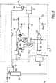
- the supply comprises an autotransformer 10 connected to the mains electrical power supply by means of a switch 11 and having a first output 10a for supplying a starting voltage and a second output 10b for supplying a working voltage lower than the starting voltage. It also comprises a controllable switch 12 and a control circuit module 13.
- a set of lamps represented by a generic load 14, is connected to the autotransformer by means of the switch 12 in order to receive the starting voltage or the working voltage therefrom.
- the switch 12 is part of a relay but, in practice, it could be formed by one or more solid-state components such as transistors or TRIACs.
- the control circuit module 13 has the function of generating a switching signal for the switch 12 in various operating conditions.
- the module 13 comprises a current detector 15, for example, a toroidal magnetic circuit which detects the current absorbed by the load 14, a circuit 16, for example, a peak detector, for processing the signal of the detector 15, a calibration device 17, a first voltage comparator 18, a voltage detector 19, for example, a voltage divider with rectifiers, a second voltage comparator 20, and a relay driver stage 21 with a timer T and a relay coil 24 which operates the switch 12.
- the outputs of the comparators 18 and 20 are connected to the resetting and starting input of the timer 21 by means of respective decoupling diodes 22 and 23 which together form an OR logic function, as well as to respective indicator devices, for example two LEDs 25 and 26.
- One of the inputs of each of the comparators is connected to a respective trimmer 27 or 28 which sets its voltage to an adjustable reference value.
- the calibration device 17 is constituted by a voltage divider R1, R2 and by a push-button 17a, that is, a normally-open switch connected in parallel with one of the resistors of the divider.
- the phase and neutral terminals of an alternating-current mains electrical power supply (for example, 230 V, 50 Hz) are indicated L and N and the terminals of a direct-current voltage supply (for example, 12V) are indicated Vcc and by the earth symbol.
- the switch 12 has a rest position which is its position when the coil 24 is not energized. In this position, the higher voltage of the supply, that is, in this embodiment 230V, can be applied to the load 14.
- the timer T of the driver stage 21 is reset and started.
- the functional resetting relationship is represented by a broken line which joins the resetting input of the timer T of the stage 21 to the switch 11. In practice, it may be formed by an RC circuit which reacts to the starting transient of the circuit so as to bring the input terminal of the timer to the voltage necessary for resetting.
- the driver stage 21 energizes the coil 24 of the relay, causing the switch 12 to switch so that the load is supplied with the working voltage.
- the comparator 20 If the working voltage falls below a predetermined threshold value, for example, because of a reduction in the mains voltage, so that the operative state of the lamp is no longer ensured, the comparator 20 generates an output signal which brings about resetting and restarting of the timer of the stage 21 and thus de-energization of the coil 24 and switching of the switch 12 to the position in which the load is supplied with the higher voltage. This takes place if the drop in the mains voltage is of a duration greater than a predetermined period of time, for example, of a few seconds, determined by a suitable device (not shown), for example, an RC circuit.
- the detector 15 detects the current absorbed by the load.
- the signal generated thereby can be used to activate an indicator device (not shown) which supplies an indication of the state of the lamps to personnel managing the system.
- the comparator 18 If the current detected is reduced by a predetermined value relative to the nominal current (for example, as a result of a group of lamps becoming inoperative) the comparator 18 generates an output signal which brings about resetting and restarting of the timer 21 and switching of the switch 12 again to supply the load with a higher voltage. If the current drop was due to a group of lamps becoming inoperative, the increase in voltage starts the lamps again so that, except in the event of an irreversible breakdown, the lamps remain operative, even when the working voltage is re-established.
- the intervention threshold of the comparator 18 is set by the user by means of the trimmer 27. Since the current absorbed depends on the load, the trimmer 27 should be adjusted each time the load is changed, with the use of suitable instruments to measure the nominal current and the threshold current (which is usually selected to as to be approximately 30% lower than the nominal current).
- this adjustment is greatly simplified by the calibration device 17.
- the adjustment is performed when the load is supplied with the working voltage.
- the resistors are selected in a manner such that the ratio between the resistance of the resistor R2, that is, the resistor which is connected in parallel with the switch 17a, and the sum of the resistances of R1 and R2, is equal to the ratio between the threshold current at which intervention is required and the nominal current.
- the adjustment is performed by closing the push-button switch 17a and at the same time adjusting the trimmer 27 until the indicator 25 is lit.
- the closure of the switch 17a causes a reduction in the load of the peak detector 16, which causes a reduction in the voltage at the terminal of the comparator 18 to the value which it would have if the current absorbed by the lamps 14 were reduced by the desired percentage.
- This operation enables the circuit to be adjusted to the load 14 without the use of additional instruments.
- the circuit module 13 can be used without modifications, with any load, with a simple calibration operation.
- a connection is provided between the device 17 and the resetting terminal of the timer by means of a diode 29. During the closure of the switch 17a, this connection has the effect of connecting the output of the comparator to earth through the two diodes 22 and 29, thus preventing the voltage at the input of the timer T from reaching the resetting value.
- a device similar to the device 17 may also be provided at the input of the comparator 20 to facilitate the adjustment of the intervention threshold when the voltage in the load is reduced.
- the calibration device which is indicated 17' in this case, comprises a micro-controller MC with a program resident in an internal ROM memory or in an external non-volatile memory (an EPROM), and with an incorporated or external analog/digital converter (A/D), a digital trimmer, that is, a digitally-controlled voltage divider, indicated G, a starting push-button S, an electrically-programmable and erasable non-volatile memory (EEPROM) E for holding data in the event of a failure of the supply of the micro-controller, a keyboard K for the input of data defining the relationship between the intervention threshold current and the nominal current absorbed by the load, and an indicator D for displaying data and messages.
- the trimmer 27 of Figure 1 there is a second digital trimmer F controlled by an output of the micro-controller MC.
- Operation of the push-button S starts the program resident in the micro-controller MC, that is, the selection of the relationship between the desired threshold current and the nominal current absorbed. In practice, this is achieved by a corresponding adjustment of the electronic trimmer G and of the electronic trimmer F such as to equalize the voltages at the inputs of the comparator 18.
- the embodiment shown in Figure 3 uses a switch 12' as switching means operated by the relay and an inductor 10' connected in parallel with the switch as a voltage transducer. Then the switch 11 is closed, the switch 12' is closed, so that the load 14 is supplied at the mains voltage.
- the driver stage 21 energizes the coil 24 of the relay, causing the switch 12' to open and the load 14 thus to be supplied by means of the inductor 10' in series.
- the inductance of the inductor 10' is selected in a manner such that the voltage drop caused thereby is such that the load has the desired working voltage.
- the supply according to the invention achieves a saving in electrical energy together with complete reliability of the correct supply to the lamps. Moreover, the semi-automatic or automatic adjustment to the load enables the supply to be installed without problems even by unskilled personnel.
Landscapes
- Circuit Arrangements For Discharge Lamps (AREA)
- Lighting Device Outwards From Vehicle And Optical Signal (AREA)
- Circuit Arrangement For Electric Light Sources In General (AREA)
- Luminescent Compositions (AREA)
Applications Claiming Priority (2)
| Application Number | Priority Date | Filing Date | Title |
|---|---|---|---|
| IT1999MI000774A IT1312178B1 (it) | 1999-04-14 | 1999-04-14 | Alimentatore per lampade a scarica. |
| ITMI990774 | 1999-04-14 |
Publications (2)
| Publication Number | Publication Date |
|---|---|
| EP1045621A1 true EP1045621A1 (fr) | 2000-10-18 |
| EP1045621B1 EP1045621B1 (fr) | 2003-01-15 |
Family
ID=11382722
Family Applications (1)
| Application Number | Title | Priority Date | Filing Date |
|---|---|---|---|
| EP00201246A Expired - Lifetime EP1045621B1 (fr) | 1999-04-14 | 2000-04-05 | Alimentation pour lampe à décharge |
Country Status (4)
| Country | Link |
|---|---|
| EP (1) | EP1045621B1 (fr) |
| AT (1) | ATE231325T1 (fr) |
| DE (1) | DE60001191T2 (fr) |
| IT (1) | IT1312178B1 (fr) |
Citations (4)
| Publication number | Priority date | Publication date | Assignee | Title |
|---|---|---|---|---|
| JPS56112046A (en) * | 1980-02-07 | 1981-09-04 | Toshiba Corp | Starting voltage testing device for fluorescent lamp |
| US4434388A (en) * | 1981-09-03 | 1984-02-28 | Carver Leroy J | Electrical lighting controller |
| JPH0589978A (ja) * | 1991-09-27 | 1993-04-09 | Toshiba Lighting & Technol Corp | 放電ランプ点灯装置および照明器具 |
| GB2337644A (en) * | 1998-05-22 | 1999-11-24 | Mackwell Electronics Limited | Starting and warming up of fluorescent lamps |
-
1999
- 1999-04-14 IT IT1999MI000774A patent/IT1312178B1/it active
-
2000
- 2000-04-05 DE DE60001191T patent/DE60001191T2/de not_active Expired - Fee Related
- 2000-04-05 AT AT00201246T patent/ATE231325T1/de not_active IP Right Cessation
- 2000-04-05 EP EP00201246A patent/EP1045621B1/fr not_active Expired - Lifetime
Patent Citations (4)
| Publication number | Priority date | Publication date | Assignee | Title |
|---|---|---|---|---|
| JPS56112046A (en) * | 1980-02-07 | 1981-09-04 | Toshiba Corp | Starting voltage testing device for fluorescent lamp |
| US4434388A (en) * | 1981-09-03 | 1984-02-28 | Carver Leroy J | Electrical lighting controller |
| JPH0589978A (ja) * | 1991-09-27 | 1993-04-09 | Toshiba Lighting & Technol Corp | 放電ランプ点灯装置および照明器具 |
| GB2337644A (en) * | 1998-05-22 | 1999-11-24 | Mackwell Electronics Limited | Starting and warming up of fluorescent lamps |
Non-Patent Citations (2)
| Title |
|---|
| PATENT ABSTRACTS OF JAPAN vol. 005, no. 186 (E - 084) 25 November 1981 (1981-11-25) * |
| PATENT ABSTRACTS OF JAPAN vol. 017, no. 424 (E - 1410) 6 August 1993 (1993-08-06) * |
Also Published As
| Publication number | Publication date |
|---|---|
| IT1312178B1 (it) | 2002-04-09 |
| EP1045621B1 (fr) | 2003-01-15 |
| ITMI990774A1 (it) | 2000-10-14 |
| ATE231325T1 (de) | 2003-02-15 |
| DE60001191T2 (de) | 2003-10-09 |
| DE60001191D1 (de) | 2003-02-20 |
Similar Documents
| Publication | Publication Date | Title |
|---|---|---|
| US6445141B1 (en) | Power supply for gas discharge lamp | |
| US6972531B2 (en) | Method for operating at least one low-pressure discharge lamp | |
| US4593234A (en) | Programmable apparatus for controlling illuminating lamps | |
| US6208090B1 (en) | Reduced voltage and time delay to eliminate filament hot shock | |
| CN102204410B (zh) | 控制0-10v调暗接口电路与dali电路以调暗照明装置的方法 | |
| US5821642A (en) | Arc prevention circuit for a mechanical switch | |
| US7957112B2 (en) | Protection circuit for limiting operating power of electrical device and method thereof | |
| US20030160573A1 (en) | Auxiliary controller | |
| JP4814250B2 (ja) | 負荷開放検出機能を有する電力スイッチング装置 | |
| US20030160578A1 (en) | Apparatus for lighting a discharge lamp at electric characteristics appropriate to a type of the discharge lamp | |
| KR20100047307A (ko) | 방전 램프들을 위한 전자 동작 장치들을 프로그래밍하기 위한 방법, 및 방전 램프들을 위한 전자 동작 장치 | |
| JP2951578B2 (ja) | 蛍光ランプのための電子スタータ回路 | |
| US7688004B2 (en) | Device for the controlled switching of a lamp, use of the device and corresponding operating method | |
| EP1045621B1 (fr) | Alimentation pour lampe à décharge | |
| EP1404162B1 (fr) | Ballast avec protection adaptative en cas de détection de fin de durée de vie | |
| US7139680B2 (en) | Apparatus and method for standby lighting | |
| WO2003043387A1 (fr) | Ensemble circuit | |
| JPH11329778A (ja) | 負荷の作動回路 | |
| US20220190595A1 (en) | Avalanche triggered overvoltage protection | |
| US8004217B2 (en) | Electronic ballast with integral shutdown timer | |
| KR20220090722A (ko) | 지능형 조명등 제어 장치 및 방법 | |
| JP2000088897A (ja) | 電源異電圧印加表示回路 | |
| JPH08203677A (ja) | 電力制御回路 | |
| WO2006070958A1 (fr) | Ballast permettant d'economiser l'energie et de regler l'intensite d'eclairage | |
| JP2007135305A (ja) | Dc/dcコンバータ |
Legal Events
| Date | Code | Title | Description |
|---|---|---|---|
| PUAI | Public reference made under article 153(3) epc to a published international application that has entered the european phase |
Free format text: ORIGINAL CODE: 0009012 |
|
| AK | Designated contracting states |
Kind code of ref document: A1 Designated state(s): AT BE CH CY DE DK ES FI FR GB GR IE IT LI LU MC NL PT SE |
|
| AX | Request for extension of the european patent |
Free format text: AL;LT;LV;MK;RO;SI |
|
| 17P | Request for examination filed |
Effective date: 20010329 |
|
| AKX | Designation fees paid |
Free format text: AT BE CH CY DE DK ES FI FR GB GR IE IT LI LU MC NL PT SE |
|
| 17Q | First examination report despatched |
Effective date: 20010619 |
|
| GRAG | Despatch of communication of intention to grant |
Free format text: ORIGINAL CODE: EPIDOS AGRA |
|
| GRAG | Despatch of communication of intention to grant |
Free format text: ORIGINAL CODE: EPIDOS AGRA |
|
| GRAH | Despatch of communication of intention to grant a patent |
Free format text: ORIGINAL CODE: EPIDOS IGRA |
|
| RIN1 | Information on inventor provided before grant (corrected) |
Inventor name: STECICH, MAURO |
|
| GRAH | Despatch of communication of intention to grant a patent |
Free format text: ORIGINAL CODE: EPIDOS IGRA |
|
| GRAA | (expected) grant |
Free format text: ORIGINAL CODE: 0009210 |
|
| AK | Designated contracting states |
Kind code of ref document: B1 Designated state(s): AT BE CH CY DE DK ES FI FR GB GR IE IT LI LU MC NL PT SE |
|
| PG25 | Lapsed in a contracting state [announced via postgrant information from national office to epo] |
Ref country code: NL Free format text: LAPSE BECAUSE OF FAILURE TO SUBMIT A TRANSLATION OF THE DESCRIPTION OR TO PAY THE FEE WITHIN THE PRESCRIBED TIME-LIMIT Effective date: 20030115 Ref country code: LI Free format text: LAPSE BECAUSE OF FAILURE TO SUBMIT A TRANSLATION OF THE DESCRIPTION OR TO PAY THE FEE WITHIN THE PRESCRIBED TIME-LIMIT Effective date: 20030115 Ref country code: GR Free format text: LAPSE BECAUSE OF FAILURE TO SUBMIT A TRANSLATION OF THE DESCRIPTION OR TO PAY THE FEE WITHIN THE PRESCRIBED TIME-LIMIT Effective date: 20030115 Ref country code: FR Free format text: LAPSE BECAUSE OF NON-PAYMENT OF DUE FEES Effective date: 20030115 Ref country code: FI Free format text: LAPSE BECAUSE OF FAILURE TO SUBMIT A TRANSLATION OF THE DESCRIPTION OR TO PAY THE FEE WITHIN THE PRESCRIBED TIME-LIMIT Effective date: 20030115 Ref country code: CH Free format text: LAPSE BECAUSE OF FAILURE TO SUBMIT A TRANSLATION OF THE DESCRIPTION OR TO PAY THE FEE WITHIN THE PRESCRIBED TIME-LIMIT Effective date: 20030115 Ref country code: BE Free format text: LAPSE BECAUSE OF FAILURE TO SUBMIT A TRANSLATION OF THE DESCRIPTION OR TO PAY THE FEE WITHIN THE PRESCRIBED TIME-LIMIT Effective date: 20030115 Ref country code: AT Free format text: LAPSE BECAUSE OF FAILURE TO SUBMIT A TRANSLATION OF THE DESCRIPTION OR TO PAY THE FEE WITHIN THE PRESCRIBED TIME-LIMIT Effective date: 20030115 |
|
| REG | Reference to a national code |
Ref country code: GB Ref legal event code: FG4D Ref country code: CH Ref legal event code: EP |
|
| REG | Reference to a national code |
Ref country code: IE Ref legal event code: FG4D |
|
| REF | Corresponds to: |
Ref document number: 60001191 Country of ref document: DE Date of ref document: 20030220 Kind code of ref document: P |
|
| PG25 | Lapsed in a contracting state [announced via postgrant information from national office to epo] |
Ref country code: LU Free format text: LAPSE BECAUSE OF NON-PAYMENT OF DUE FEES Effective date: 20030405 Ref country code: CY Free format text: LAPSE BECAUSE OF FAILURE TO SUBMIT A TRANSLATION OF THE DESCRIPTION OR TO PAY THE FEE WITHIN THE PRESCRIBED TIME-LIMIT Effective date: 20030405 |
|
| PG25 | Lapsed in a contracting state [announced via postgrant information from national office to epo] |
Ref country code: IE Free format text: LAPSE BECAUSE OF NON-PAYMENT OF DUE FEES Effective date: 20030407 |
|
| PG25 | Lapsed in a contracting state [announced via postgrant information from national office to epo] |
Ref country code: SE Free format text: LAPSE BECAUSE OF FAILURE TO SUBMIT A TRANSLATION OF THE DESCRIPTION OR TO PAY THE FEE WITHIN THE PRESCRIBED TIME-LIMIT Effective date: 20030415 Ref country code: PT Free format text: LAPSE BECAUSE OF FAILURE TO SUBMIT A TRANSLATION OF THE DESCRIPTION OR TO PAY THE FEE WITHIN THE PRESCRIBED TIME-LIMIT Effective date: 20030415 Ref country code: DK Free format text: LAPSE BECAUSE OF FAILURE TO SUBMIT A TRANSLATION OF THE DESCRIPTION OR TO PAY THE FEE WITHIN THE PRESCRIBED TIME-LIMIT Effective date: 20030415 |
|
| PG25 | Lapsed in a contracting state [announced via postgrant information from national office to epo] |
Ref country code: MC Free format text: LAPSE BECAUSE OF NON-PAYMENT OF DUE FEES Effective date: 20030430 |
|
| NLV1 | Nl: lapsed or annulled due to failure to fulfill the requirements of art. 29p and 29m of the patents act | ||
| PG25 | Lapsed in a contracting state [announced via postgrant information from national office to epo] |
Ref country code: ES Free format text: LAPSE BECAUSE OF FAILURE TO SUBMIT A TRANSLATION OF THE DESCRIPTION OR TO PAY THE FEE WITHIN THE PRESCRIBED TIME-LIMIT Effective date: 20030730 |
|
| REG | Reference to a national code |
Ref country code: CH Ref legal event code: PL |
|
| PLBE | No opposition filed within time limit |
Free format text: ORIGINAL CODE: 0009261 |
|
| STAA | Information on the status of an ep patent application or granted ep patent |
Free format text: STATUS: NO OPPOSITION FILED WITHIN TIME LIMIT |
|
| EN | Fr: translation not filed | ||
| 26N | No opposition filed |
Effective date: 20031016 |
|
| REG | Reference to a national code |
Ref country code: IE Ref legal event code: MM4A |
|
| PGFP | Annual fee paid to national office [announced via postgrant information from national office to epo] |
Ref country code: GB Payment date: 20040316 Year of fee payment: 5 |
|
| PGFP | Annual fee paid to national office [announced via postgrant information from national office to epo] |
Ref country code: DE Payment date: 20040330 Year of fee payment: 5 |
|
| PG25 | Lapsed in a contracting state [announced via postgrant information from national office to epo] |
Ref country code: IT Free format text: LAPSE BECAUSE OF NON-PAYMENT OF DUE FEES Effective date: 20050405 Ref country code: GB Free format text: LAPSE BECAUSE OF NON-PAYMENT OF DUE FEES Effective date: 20050405 |
|
| PG25 | Lapsed in a contracting state [announced via postgrant information from national office to epo] |
Ref country code: DE Free format text: LAPSE BECAUSE OF NON-PAYMENT OF DUE FEES Effective date: 20051101 |
|
| GBPC | Gb: european patent ceased through non-payment of renewal fee |
Effective date: 20050405 |