EP1047539B1 - Forming fastener products - Google Patents
Forming fastener products Download PDFInfo
- Publication number
- EP1047539B1 EP1047539B1 EP98918078A EP98918078A EP1047539B1 EP 1047539 B1 EP1047539 B1 EP 1047539B1 EP 98918078 A EP98918078 A EP 98918078A EP 98918078 A EP98918078 A EP 98918078A EP 1047539 B1 EP1047539 B1 EP 1047539B1
- Authority
- EP
- European Patent Office
- Prior art keywords
- mold
- preform
- forming
- molding
- elements
- Prior art date
- Legal status (The legal status is an assumption and is not a legal conclusion. Google has not performed a legal analysis and makes no representation as to the accuracy of the status listed.)
- Expired - Lifetime
Links
- 239000000047 product Substances 0.000 claims description 43
- 238000000034 method Methods 0.000 claims description 28
- 238000000465 moulding Methods 0.000 claims description 20
- 238000001746 injection moulding Methods 0.000 claims description 12
- 238000002347 injection Methods 0.000 claims description 7
- 239000007924 injection Substances 0.000 claims description 7
- 230000013011 mating Effects 0.000 claims description 4
- 239000012467 final product Substances 0.000 claims description 2
- 238000004519 manufacturing process Methods 0.000 description 5
- 239000000463 material Substances 0.000 description 4
- 230000000717 retained effect Effects 0.000 description 3
- 241000191291 Abies alba Species 0.000 description 2
- 208000015943 Coeliac disease Diseases 0.000 description 2
- 239000011347 resin Substances 0.000 description 2
- 229920005989 resin Polymers 0.000 description 2
- 241000269627 Amphiuma means Species 0.000 description 1
- 239000004743 Polypropylene Substances 0.000 description 1
- 230000015572 biosynthetic process Effects 0.000 description 1
- 230000008878 coupling Effects 0.000 description 1
- 238000010168 coupling process Methods 0.000 description 1
- 238000005859 coupling reaction Methods 0.000 description 1
- 230000009477 glass transition Effects 0.000 description 1
- 239000000155 melt Substances 0.000 description 1
- 239000002991 molded plastic Substances 0.000 description 1
- 238000005192 partition Methods 0.000 description 1
- -1 polypropylene Polymers 0.000 description 1
- 229920001155 polypropylene Polymers 0.000 description 1
- 238000003825 pressing Methods 0.000 description 1
- 238000000926 separation method Methods 0.000 description 1
- 239000007787 solid Substances 0.000 description 1
- 229920001169 thermoplastic Polymers 0.000 description 1
- 239000004416 thermosoftening plastic Substances 0.000 description 1
- 238000009966 trimming Methods 0.000 description 1
Images



Classifications
-
- B—PERFORMING OPERATIONS; TRANSPORTING
- B29—WORKING OF PLASTICS; WORKING OF SUBSTANCES IN A PLASTIC STATE IN GENERAL
- B29C—SHAPING OR JOINING OF PLASTICS; SHAPING OF MATERIAL IN A PLASTIC STATE, NOT OTHERWISE PROVIDED FOR; AFTER-TREATMENT OF THE SHAPED PRODUCTS, e.g. REPAIRING
- B29C67/00—Shaping techniques not covered by groups B29C39/00 - B29C65/00, B29C70/00 or B29C73/00
- B29C67/0044—Shaping techniques not covered by groups B29C39/00 - B29C65/00, B29C70/00 or B29C73/00 for shaping edges or extremities
-
- A—HUMAN NECESSITIES
- A44—HABERDASHERY; JEWELLERY
- A44B—BUTTONS, PINS, BUCKLES, SLIDE FASTENERS, OR THE LIKE
- A44B18/00—Fasteners of the touch-and-close type; Making such fasteners
- A44B18/0046—Fasteners made integrally of plastics
- A44B18/0049—Fasteners made integrally of plastics obtained by moulding processes
-
- B—PERFORMING OPERATIONS; TRANSPORTING
- B29—WORKING OF PLASTICS; WORKING OF SUBSTANCES IN A PLASTIC STATE IN GENERAL
- B29C—SHAPING OR JOINING OF PLASTICS; SHAPING OF MATERIAL IN A PLASTIC STATE, NOT OTHERWISE PROVIDED FOR; AFTER-TREATMENT OF THE SHAPED PRODUCTS, e.g. REPAIRING
- B29C45/00—Injection moulding, i.e. forcing the required volume of moulding material through a nozzle into a closed mould; Apparatus therefor
- B29C45/0053—Injection moulding, i.e. forcing the required volume of moulding material through a nozzle into a closed mould; Apparatus therefor combined with a final operation, e.g. shaping
- B29C45/0055—Shaping
Definitions
- Thermoplastic fastener products having an array of integrally formed, upstanding, engageable fastener elements are employed in a wide variety of instances to enable releasable attachment of two surfaces. Often such products are formed in discrete mold cavities by injection molding techniques. Some such fastener products are said to be “self-engaging”, that is, capable. of engaging an identical product to form a fastening. Some self-engaging fastener elements are called “mushroom-shaped" because they have stems with overhanging heads. Because of their widespread commercial use, more efficient and cost-effective methods and machines for producing these fastener products are desirable.
- US 3,031,730 discloses a coupling element, wherein a surface of the element includes a multiplicity of burrs extending tranversely and longitudinally of the element.
- the burrs are manufactured in two steps. First, in an injection molding step the burrs are initially formed as pointed cones or tooth-like burr forming members which are then in a second step formed into hook-shaped members. For transferring the injection molded plate with the burr-forming members from a molding station to a forming station and then to a trimming station, a sprue of the molded plastic material is engaged by a pin which moves the element to the next station.
- this method requires engaging of the sprues for transferring the elements which makes the method more complicated.
- US 4,861,399 discloses an apparatus and a method for producing a fastener means of the type having a plurality of fastening means extending from bight portions bonded to a backing material. in this method an array of filaments is formed into loops and then arranged on a backing material. Then the loops are cut and the free ends are formed into a hook like shape. This method is very complicated and requires a complex apparatus for forming and attaching the filaments.
- a method of forming a fastener product includes the steps of molding a preform member in a mold cavity defined by first and second parts of a mold, removing the first part of the mold to expose an array of preform elements of the preform member while the member remains within the second part of the mold, and, while holding the member by the second part of the mold, performing a subsequent forming operation on the preform elements.
- array we mean that there are at least about 10 preform elements, preferably more than about 30 preform elements.
- the elements may be in any arrangement suitable for performing their intended fastening function, and may form geometric patterns.
- the subsequent forming operation permanently deforms the preform elements by heat and pressure.
- the preform elements have stems and the subsequent forming operation forms overhanging heads on the preform stems.
- the heads are mushroom-shaped.
- the method includes the steps of forming a holding feature integral with the product during the molding process and holding the product by the holding feature within the second part of the mold during the subsequent forming operation.
- the holding feature is a fastening element constructed for releasable fastening to a mating member after the subsequent forming operation.
- the method includes moving the second part of the mold from an injection-molding location to a subsequent forming location.
- the second part of the mold is moved along a reciprocal path, and in some other cases it is moved in a rotary sense.
- an apparatus for forming a fastener product has at least two molds in which a preform member is injection molded. Each mold has at least a first and second part, the first part being removable from the second part to expose an array of preform elements of the preform member while the member remains within the second part of the mold.
- the apparatus includes a forming device to deform the preform elements to form fastener elements while holding the member by the second part of the mold.
- the forming device includes a heated mold plate.
- the second part of the mold is constructed to define a molding cavity to both form an injection-molded feature of the final product and hold the preform member by the feature while the fastener elements are formed.
- the feature is a fastening element.
- the apparatus also includes an injection-molding location, a forming location, and means to move the second part of one of the two molds to the injection-molding location and simultaneously move the second part of the other of the two molds to the forming location.
- the means is constructed to move the second parts of the two molds along a reciprocal path; in some other cases the means is constructed to move the second parts of the two molds in a rotary sense.
- the apparatus is constructed and arranged to injection mold a first preform member in one of the two molds while simultaneously deforming the preform elements of a second preform member in the other of the two molds.
- an apparatus for forming a fastener product includes
- Employing the second part of the mold to hold the preform member during the subsequent forming operation advantageously locates and supports the preform product for improved head formation.
- the molding process is simple, not requiring complicated slides to open otherwise die-locked mushroom-shaped cavities or deforming solidified fastener elements to pull them from the mold.
- the post-forming process enables the production of heads with extensive overhanging portions that would be difficult to pull intact from solid mold cavities.
- Providing an apparatus with a forming location separate from a molding location, arranged such that molds may be moved between the forming and molding locations in either a reciprocating or rotary motion enables efficient production cycle times and low production costs.
- the holding feature of the finished fastener product advantageously, in some preferred embodiments, provides a means of permanently or releasably securing the fastener product during use.
- an injection mold 10 for molding a fastener product preform consists of an upper part 12 and a lower part 14.
- Lower part 14 has two sections, 16 and 18, abutting at seam 20. Together, lower part sections 16 and 18 and upper part 12 define a mold cavity 22 shaped to form the preform product.
- a runner 24 and gate 26 provide means to inject molten resin into cavity 22.
- FIG. 2 after resin 28 has been injected into mold 10 to form a preform fastener product 30, upper mold part 12 is removed to expose an array of upstanding preform stems 32 integrally molded with preform product 30. For illustration, only two stems 32 are shown to represent an entire array.
- preform 30 is held within lower mold part 14 by a holding feature 34 of preform 30.
- holding feature 34 comprises a "christmas tree"-type fastener element, as shown, although other feature shapes may be employed to retain preform 30 in lower mold part 14 while the mold is opened to expose stems 32.
- stems 32 are permanently deformed by a heated forming plate 36 to form overhanging heads 38 suitable for releasably fastening the completed fastener product 40 to a mating surface in use.
- Forming plate 36 has cavities 39 shaped to form heads 38 by applying downward pressure against stems 32 by plate 36. Because the preform product 30 has been securely retained in lower mold part 14, stems 32 are maintained in a precise, known position (accounting for predictable material shrinkage) so that heated forming plate 36 can be lowered with cavities 39 in proper alignment.
- the lower regions of the stems, away from the direct contact of the forming plate cavities, remain at a lower temperature at which they retain their structural integrity to support the pressure applied by the forming plate.
- the lower part of the mold provides sturdy support for the preform product during the application of the head-forming pressure.
- polypropylene with a glass transition temperature T g below room temperature and a melt temperature T m of about 300 degrees F, was molded to produce a preform product having an array of 0.08 inch long cylindrical stems 32 of 0.012 inch diameter.
- Mushroom-shaped heads of about 0.040 inch final diameter, were post-formed on the stems using a forming plate 36 heated to a temperature of 375 degrees F. The forming plate was held against the stems for about 1.5 seconds, loaded with a consistent pressure equivalent to about 2.5 pounds per square inch on the lower portions of the preform stems, and then removed.
- Figs. 7 through 9 sequentially illustrate the head-forming process of Figs. 3 through 5 to produce a finished fastener product 42 (Fig. 10) with an array of mushroom-shaped headed fastener elements 44 opposite a holding feature 34.
- fastener elements 44 By permanently attaching fastener product 42 to a surface by means of holding feature 34 (e.g. by pressing christmas tree feature 34 through a hole in the surface), fastener elements 44 provide a means of releasably attaching a mating fastener product to the surface.
- fastener elements 44 are self-engaging, mushroom-shaped elements that develop high separation loads with relatively low engagement loads.
- Such double-sided fasteners have several useful applications, such as in attaching automobile trim and interior panels and carpeting, office partition panels and chair seat backs.
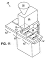
- Figs. 11 and 12 are two embodiments of multiple-station machines, 48 and 49, respectively, for molding and post-forming fastener products, each having a molding station 50 and a forming station 52.
- lower mold parts 14' are mounted on a sliding table 53 which moves the lower molds reciprocally between a central molding station 50 and either of two forming stations 52.
- lower mold parts 14" are mounted on a rotary table 54 which moves the lower molds between molding station 50, forming station 52, and an ejection station 56.
- molding station 50 is shown as a vertical injection molding station with a hopper 58, an injector 60, and an upper mold part 12.
- Upper mold part 12 is lowered to one of the lower mold parts during the injection process.
- Forming station 52 has a heated forming plate 36 which is lowered to form heads on the molded fastener product preforms.
- Both machines 48 and 49 are arranged to enable a forming station 52 to post-form heads on one preform product while molding station 50 is molding another preform product.
- sliding table 53 alternatingly places a lower mold part 14' under either the left-hand or right-hand forming plate 36 for a given cycle.
- rotary machine 49 of Fig. 12 four stations are shown, although two or more may be employed as needed.
- lower mold part 14 comprises more than two sections, as illustrated in mold parts 14' of Fig. 11, to define multiple mold cavities.
- the lower mold part is a single piece and ejector pins are employed to remove the holding feature of the finished product from the mold cavity.
Landscapes
- Engineering & Computer Science (AREA)
- Mechanical Engineering (AREA)
- Manufacturing & Machinery (AREA)
- Moulds For Moulding Plastics Or The Like (AREA)
Description
"christmas tree"-type fastener element, as shown, although other feature shapes may be employed to retain
Claims (17)
- A method of forming a fastener product comprising:characterized bymolding a preform member (30) in a mold cavity (22) defined by first (12) and second parts (14) of a mold (10),
removing the first part (12) of the mold (10) to expose an array of preform elements (32) of the preform member (30) while the member (30) remains within the second part (14) of the mold (10), and
while holding the member (30) by the second part (14) of the mold (10), performing a subsequent forming operation on the preform elements (32). - The method of claim 1 wherein the subsequent forming operation comprises permanently deforming the preform elements (32) by heat and pressure.
- The method of claim 2 wherein the preform elements comprise stems (32) and the subsequent forming operation comprises forming overhanging heads (38) on the preform stems (32).
- The method of claim 3 wherein the heads (38) are mushroom-shaped.
- The method of claim 1 comprising forming a holding feature (34) integral with the product during said molding process, and holding the product by said holding feature (34) within the second part (14) of the mold (10) during the subsequent forming operation.
- The method of claim 5 in which the holding feature (34) is a fastening element constructed for releasable fastening to a mating member after the subsequent forming operation.
- The method of claim 1 comprising moving the second part (14) of the mold (10) from an injection-molding location (50) to a subsequent forming location (52).
- The method of claim 7 in which the second part (14) of the mold (10) is moved along a reciprocal path between the injection-molding location (50) and the forming location (52).
- The method of claim 7 in which the second part (14) of the mold (10) is moved in a rotary sense between the injection-molding location (50) and the forming location (52).
- An apparatus for forming a fastener product comprising
a mold (10) for injection molding a preform member (30) having preform elements (32), the mold (10) having a first (12) and second part (14),
and a forming device (36) to deform the preform elements (32) to form fastener elements,
characterized in that
the first part (12) is removable from the second part (14) to expose an array of preform elements (32) of the preform member (30) while the member (30) remains within the second part (14) of the mold (10) and that the forming device is able to deform the preform elements while holding the member (30) by the second part (14) of the mold (10). - The apparatus of claim 10 wherein the forming device comprises a heated mold plate (36).
- The apparatus of claim 10 wherein the second part (14) of the mold (10) is constructed to define a molding cavity (22) to both form an injection-molded feature (34) of the final product and hold the preform member (30) by the feature (34) while the fastener elements (44) are formed.
- The apparatus of claim 12 wherein the feature is a fastening element (34).
- The apparatus of claim 10 further comprising an injection-molding location (50). a forming location (52), and means to move the second part (14) of said mold (10) to the injection-molding location (50) and simultaneously move the second part of another mold to the forming location (52).
- The apparatus of claim 14 wherein said means is constructed to move the second part (14) of said mold (10) along a reciprocal path.
- The apparatus of claim 14 wherein said means is constructed to move the second part (14) of said mold (10) in a rotary sense.
- The apparatus of claim 10 constructed and arranged to injection mold a first preform member (30) in one of two molds (14'; 14") while simultaneously deforming the preform elements (32) of a second preform member (30) in the other (14'; 14") of said two moulds.
Applications Claiming Priority (3)
| Application Number | Priority Date | Filing Date | Title |
|---|---|---|---|
| US843017 | 1977-10-17 | ||
| US08/843,017 US5980230A (en) | 1997-04-11 | 1997-04-11 | Forming fastener products |
| PCT/US1998/007170 WO1998046417A1 (en) | 1997-04-11 | 1998-04-09 | Forming fastener products |
Publications (3)
| Publication Number | Publication Date |
|---|---|
| EP1047539A1 EP1047539A1 (en) | 2000-11-02 |
| EP1047539A4 EP1047539A4 (en) | 2000-11-02 |
| EP1047539B1 true EP1047539B1 (en) | 2004-09-01 |
Family
ID=25288845
Family Applications (1)
| Application Number | Title | Priority Date | Filing Date |
|---|---|---|---|
| EP98918078A Expired - Lifetime EP1047539B1 (en) | 1997-04-11 | 1998-04-09 | Forming fastener products |
Country Status (6)
| Country | Link |
|---|---|
| US (1) | US5980230A (en) |
| EP (1) | EP1047539B1 (en) |
| AU (1) | AU7106898A (en) |
| DE (1) | DE69826033D1 (en) |
| ES (1) | ES2227828T3 (en) |
| WO (1) | WO1998046417A1 (en) |
Cited By (3)
| Publication number | Priority date | Publication date | Assignee | Title |
|---|---|---|---|---|
| DE102005048215A1 (en) * | 2005-09-29 | 2007-04-05 | Gottlieb Binder Gmbh & Co. Kg | Adhesive closure part manufacturing method for use in e.g. vehicle industry, involves inserting fixing part as whole into carrier structure, which is designed in form of U-shape before insertion |
| WO2009112133A1 (en) | 2008-03-12 | 2009-09-17 | Gottlieb Binder Gmbh & Co. Kg | Method for producing a securing object, particularly in the form of a heat-resistant adhesive closure |
| DE102009019671A1 (en) | 2009-04-30 | 2010-11-04 | Gottlieb Binder Gmbh & Co. Kg | closing part |
Families Citing this family (24)
| Publication number | Priority date | Publication date | Assignee | Title |
|---|---|---|---|---|
| US6187247B1 (en) * | 1998-05-13 | 2001-02-13 | Velcro Industries B.V. | Injection molding parts with fastener elements |
| WO2000074544A1 (en) * | 1999-06-07 | 2000-12-14 | Tac-Fast Systems S.A. | Anchor sheet attachment devices |
| FR2817925B1 (en) * | 2000-12-11 | 2003-09-19 | Renault | ATTACHMENT OF ONE PART TO ANOTHER, WITH POSITIONING IN THE THREE AXES, IN PARTICULAR FOR A VEHICLE COVERING PART |
| US7412806B2 (en) | 2001-12-13 | 2008-08-19 | Tac-Fast Georgia Llc | Structures for creating spaces while installing anchor sheet and attachment piece subfloors |
| US6687962B2 (en) | 2002-01-16 | 2004-02-10 | Velcro Industries B.V. | Fastener element patterning |
| WO2004067268A2 (en) * | 2003-01-30 | 2004-08-12 | Tac-Fast Systems Sa | System and methods of manufacturing hook plates |
| PT1589856E (en) | 2003-01-30 | 2008-07-18 | Tac Fast Systems Sa | Anchor sheet positioning and connection system |
| JP2006517269A (en) * | 2003-01-30 | 2006-07-20 | タック ファスト システムズ ソシエテ アノニム | Improved anchor sheet |
| US7192266B2 (en) * | 2004-09-28 | 2007-03-20 | Velera Industries | Molding device inserts |
| US7641469B2 (en) * | 2004-09-28 | 2010-01-05 | Velcro Industries B.V. | Fastener molding |
| US7217119B2 (en) * | 2005-05-18 | 2007-05-15 | Velcro Industries B.V. | Fastener molding |
| JP2007241887A (en) | 2006-03-10 | 2007-09-20 | Fujitsu Component Ltd | keyboard |
| US7806677B2 (en) | 2007-07-16 | 2010-10-05 | Velcro Industries B.V. | Molding apparatus and related systems and methods |
| CA2774386A1 (en) | 2011-04-15 | 2012-10-15 | Tac-Fast Systems Canada Limited | Methods and systems for engagement of decorative covering |
| EP2714375A1 (en) | 2011-06-02 | 2014-04-09 | A. Raymond et Cie | Fasteners manufactured by three-dimensional printing |
| US8916085B2 (en) | 2011-06-02 | 2014-12-23 | A. Raymond Et Cie | Process of making a component with a passageway |
| US8883064B2 (en) | 2011-06-02 | 2014-11-11 | A. Raymond & Cie | Method of making printed fastener |
| US20130255346A1 (en) * | 2012-03-29 | 2013-10-03 | A. Raymond Et Cie | Metal-stamping die manufactured by additive manufacturing |
| DE102012010893A1 (en) * | 2012-06-01 | 2013-12-05 | Gottlieb Binder Gmbh & Co. Kg | fastening system |
| US9291182B2 (en) | 2012-07-17 | 2016-03-22 | Ford Global Technologies, Llc | Vehicle attachment system having a domed-head fastener |
| US9610904B2 (en) | 2012-08-13 | 2017-04-04 | Ford Global Technologies, Llc | Push pin with over-travel stop |
| JP6180288B2 (en) * | 2013-11-08 | 2017-08-16 | 東洋ゴム工業株式会社 | Clip fixing jig and sheet pad forming die having the same |
| US10582743B2 (en) | 2016-03-21 | 2020-03-10 | Delphini, Llc | System and method for activated interlocking fasteners and seals |
| US10550580B1 (en) | 2018-08-02 | 2020-02-04 | Velcro BVBA | Acoustic panel wall mounting |
Family Cites Families (36)
| Publication number | Priority date | Publication date | Assignee | Title |
|---|---|---|---|---|
| US2499898A (en) * | 1946-12-23 | 1950-03-07 | Albert F Anderson | Clasp |
| US3031730A (en) * | 1958-09-26 | 1962-05-01 | Louis H Morin | Burr-type closure or coupling element |
| US3192589A (en) * | 1960-07-18 | 1965-07-06 | Raymond C Pearson | Separable fastener |
| US3101517A (en) * | 1960-11-28 | 1963-08-27 | Fox Marvin | Fastener |
| US3138841A (en) * | 1962-10-23 | 1964-06-30 | Naimer Jack | Separable fastening fabrics |
| US3320649A (en) * | 1962-10-23 | 1967-05-23 | Naimer Jack | Methods of making separable fastening fabrics |
| US3266113A (en) * | 1963-10-07 | 1966-08-16 | Minnesota Mining & Mfg | Interreacting articles |
| US3367809A (en) * | 1964-05-08 | 1968-02-06 | Branson Instr | Sonics |
| US3353663A (en) * | 1966-02-10 | 1967-11-21 | Minnesota Mining & Mfg | Adherent fasteners |
| US3408705A (en) * | 1966-07-07 | 1968-11-05 | Minnesota Mining & Mfg | Fastener articles |
| US3471903A (en) * | 1967-10-24 | 1969-10-14 | Minnesota Mining & Mfg | Stud-backed fasteners |
| DE1760919C3 (en) * | 1968-07-19 | 1974-03-28 | Kanebo Ltd., Tokio | Process for the production of spherical heads on the protruding thread ends of a surface zipper provided between two fabric surfaces |
| JPS4914537B1 (en) * | 1969-11-14 | 1974-04-08 | ||
| DE2060346A1 (en) * | 1969-12-09 | 1971-06-09 | Aoki K | Method and device for producing injection moldings |
| US3718725A (en) * | 1970-11-17 | 1973-02-27 | Int Knitlock Corp | Method for making hook fabric material for fasteners |
| FR2116704A5 (en) * | 1970-12-04 | 1972-07-21 | Velcro France | |
| GB1388235A (en) * | 1972-05-23 | 1975-03-26 | New Zealand Dairy Res Inst | Packaging |
| US4290174A (en) * | 1976-08-13 | 1981-09-22 | Minnesota Mining And Manufacturing Company | Separable fastener and article for making same |
| GB2027794B (en) * | 1978-08-15 | 1982-09-22 | Minnesota Mining & Mfg | Tuoch and close fasteners |
| US4709824A (en) * | 1985-12-12 | 1987-12-01 | Tri-Tech Systems International Inc. | Tamper evident plastic caps with lower separable or breakaway portions and a method of forming them |
| US4872304A (en) * | 1985-12-12 | 1989-10-10 | Tri-Tech Systems International Inc. | Closure cap with a seal and method of and apparatus for forming such closure and seal |
| US4725221A (en) * | 1986-05-23 | 1988-02-16 | John H. Blanz Company, Inc. | Improved machine for continuously producing an element of a separable fastener |
| JPH0622822B2 (en) * | 1986-06-19 | 1994-03-30 | 東芝機械株式会社 | Injection molding machine |
| US4793506A (en) * | 1987-06-10 | 1988-12-27 | Tri-Tech Systems International Inc. | Closure cap with a seal and method of and apparatus for forming such closure and seal |
| US4861399A (en) * | 1987-11-04 | 1989-08-29 | Kimberly-Clark Corporation | Apparatus and method for forming filament and loop fasteners |
| US5038455A (en) * | 1988-03-25 | 1991-08-13 | Guest John D | Method of manufacturing tube coupling bodies |
| CA1328158C (en) * | 1988-05-11 | 1994-04-05 | Toshiyuki Kanai | Multi-injection molded body, a method of molding for the same, and a multi-injection molding machine |
| US5077870A (en) * | 1990-09-21 | 1992-01-07 | Minnesota Mining And Manufacturing Company | Mushroom-type hook strip for a mechanical fastener |
| US5679302A (en) * | 1990-09-21 | 1997-10-21 | Minnesota Mining And Manufacturing Company | Method for making a mushroom-type hook strip for a mechanical fastener |
| US5160474A (en) * | 1990-12-21 | 1992-11-03 | Cadillac Rubber & Plastics, Inc. | Overmolded gasket, heat exchanger tank incorporating the same and method for making the same |
| US5272922A (en) * | 1991-03-06 | 1993-12-28 | Watson Industries, Inc. | Vibrating element angular rate sensor system and north seeking gyroscope embodiment thereof |
| DE69230253T2 (en) * | 1991-03-06 | 2000-02-24 | Aircast Inc., Summit | INJECTION MOLDED ORTHOPEDIC DEVICE AND CORRESPONDING METHOD |
| US5209889A (en) * | 1991-10-10 | 1993-05-11 | Gencorp Inc. | Method for operation of shuttle assembly for use in an injection molding machine |
| US5212853A (en) * | 1992-03-10 | 1993-05-25 | Nifco Inc. | Separable plastic fastener and method and apparatus for manufacturing thereof |
| US5242646A (en) * | 1992-05-07 | 1993-09-07 | Minnesota Mining And Manufacturing Company | Method of making an interengaging fastener member |
| JP3421075B2 (en) * | 1993-03-24 | 2003-06-30 | 日本発条株式会社 | Method for caulking thermoplastic resin member and fastener |
-
1997
- 1997-04-11 US US08/843,017 patent/US5980230A/en not_active Expired - Lifetime
-
1998
- 1998-04-09 EP EP98918078A patent/EP1047539B1/en not_active Expired - Lifetime
- 1998-04-09 DE DE69826033T patent/DE69826033D1/en not_active Expired - Lifetime
- 1998-04-09 WO PCT/US1998/007170 patent/WO1998046417A1/en not_active Ceased
- 1998-04-09 ES ES98918078T patent/ES2227828T3/en not_active Expired - Lifetime
- 1998-04-09 AU AU71068/98A patent/AU7106898A/en not_active Abandoned
Cited By (4)
| Publication number | Priority date | Publication date | Assignee | Title |
|---|---|---|---|---|
| DE102005048215A1 (en) * | 2005-09-29 | 2007-04-05 | Gottlieb Binder Gmbh & Co. Kg | Adhesive closure part manufacturing method for use in e.g. vehicle industry, involves inserting fixing part as whole into carrier structure, which is designed in form of U-shape before insertion |
| WO2009112133A1 (en) | 2008-03-12 | 2009-09-17 | Gottlieb Binder Gmbh & Co. Kg | Method for producing a securing object, particularly in the form of a heat-resistant adhesive closure |
| DE102008013890A1 (en) | 2008-03-12 | 2009-09-17 | Gottlieb Binder Gmbh & Co. Kg | Method for producing a fixed object, in particular in the form of a heat-resistant adhesive closure part |
| DE102009019671A1 (en) | 2009-04-30 | 2010-11-04 | Gottlieb Binder Gmbh & Co. Kg | closing part |
Also Published As
| Publication number | Publication date |
|---|---|
| WO1998046417A1 (en) | 1998-10-22 |
| ES2227828T3 (en) | 2005-04-01 |
| AU7106898A (en) | 1998-11-11 |
| EP1047539A1 (en) | 2000-11-02 |
| DE69826033D1 (en) | 2004-10-07 |
| US5980230A (en) | 1999-11-09 |
| EP1047539A4 (en) | 2000-11-02 |
Similar Documents
| Publication | Publication Date | Title |
|---|---|---|
| US5980230A (en) | Forming fastener products | |
| US5242646A (en) | Method of making an interengaging fastener member | |
| JP2009214438A (en) | Injection moulding apparatus and method for molding injection-molded article | |
| CN103269841A (en) | Method and device for producing fibre-einforced interior trim components comprising attachment elements for motor vehicles | |
| JP2000157310A (en) | Fasteners with tape | |
| US5928464A (en) | Film laminated plastic moulding as well as process and device for its manufacture | |
| EP1153725A1 (en) | Process and equipment for hot moulding of articles made of thermoplastic material | |
| US8944796B2 (en) | Mesh and apparatus for forming and/or using mesh | |
| CN202264357U (en) | Special two-color mold for turntable type two-screw parallel jetting injection molding machine | |
| US4352654A (en) | Apparatus for the production of small synthetic resin articles | |
| JPH08164538A (en) | In-molding method and mold constitution member and apparatus thereof | |
| KR101442529B1 (en) | Apparatus and method for manufacturing Thermosetting Resin | |
| JP2010523237A (en) | Method for producing plastic adhesive fastener element and instrument for carrying out the method | |
| US4176151A (en) | Method for manufacturing an article stopper device | |
| CN221212565U (en) | Injection molding mold for automobile fog lamp decoration piece with multiple insert blocks synchronously linked to core pulling | |
| US7066051B2 (en) | Method and apparatus for forming multi-colored cap part of snap button | |
| JP2001088137A (en) | Mold for molding ring-like rubber component | |
| CN220031015U (en) | Rubber inner die convenient for filling rubber | |
| CN223834959U (en) | A mold for hook production | |
| CN211518309U (en) | Crystal base upper cover mould | |
| CN214026978U (en) | Multipurpose drawer type injection mould frame | |
| JPH065135Y2 (en) | Mold structure | |
| JPH0615682A (en) | Injection molding method and apparatus | |
| CN110103397B (en) | Double-shot injection mold with front rear mold tunnel row position | |
| JPH01295813A (en) | Injection mold |
Legal Events
| Date | Code | Title | Description |
|---|---|---|---|
| PUAI | Public reference made under article 153(3) epc to a published international application that has entered the european phase |
Free format text: ORIGINAL CODE: 0009012 |
|
| 17P | Request for examination filed |
Effective date: 19991111 |
|
| A4 | Supplementary search report drawn up and despatched |
Effective date: 20000602 |
|
| AK | Designated contracting states |
Kind code of ref document: A4 Designated state(s): DE ES FR GB IT SE Kind code of ref document: A1 Designated state(s): DE ES FR GB IT SE |
|
| 17Q | First examination report despatched |
Effective date: 20001107 |
|
| GRAP | Despatch of communication of intention to grant a patent |
Free format text: ORIGINAL CODE: EPIDOSNIGR1 |
|
| RTI1 | Title (correction) |
Free format text: FORMING FASTENER PRODUCTS |
|
| GRAS | Grant fee paid |
Free format text: ORIGINAL CODE: EPIDOSNIGR3 |
|
| GRAA | (expected) grant |
Free format text: ORIGINAL CODE: 0009210 |
|
| AK | Designated contracting states |
Kind code of ref document: B1 Designated state(s): DE ES FR GB IT SE |
|
| PG25 | Lapsed in a contracting state [announced via postgrant information from national office to epo] |
Ref country code: IT Free format text: LAPSE BECAUSE OF FAILURE TO SUBMIT A TRANSLATION OF THE DESCRIPTION OR TO PAY THE FEE WITHIN THE PRESCRIBED TIME-LIMIT;WARNING: LAPSES OF ITALIAN PATENTS WITH EFFECTIVE DATE BEFORE 2007 MAY HAVE OCCURRED AT ANY TIME BEFORE 2007. THE CORRECT EFFECTIVE DATE MAY BE DIFFERENT FROM THE ONE RECORDED. Effective date: 20040901 Ref country code: FR Free format text: LAPSE BECAUSE OF FAILURE TO SUBMIT A TRANSLATION OF THE DESCRIPTION OR TO PAY THE FEE WITHIN THE PRESCRIBED TIME-LIMIT Effective date: 20040901 |
|
| REG | Reference to a national code |
Ref country code: GB Ref legal event code: FG4D |
|
| REF | Corresponds to: |
Ref document number: 69826033 Country of ref document: DE Date of ref document: 20041007 Kind code of ref document: P |
|
| PG25 | Lapsed in a contracting state [announced via postgrant information from national office to epo] |
Ref country code: SE Free format text: LAPSE BECAUSE OF FAILURE TO SUBMIT A TRANSLATION OF THE DESCRIPTION OR TO PAY THE FEE WITHIN THE PRESCRIBED TIME-LIMIT Effective date: 20041201 |
|
| PG25 | Lapsed in a contracting state [announced via postgrant information from national office to epo] |
Ref country code: DE Free format text: LAPSE BECAUSE OF FAILURE TO SUBMIT A TRANSLATION OF THE DESCRIPTION OR TO PAY THE FEE WITHIN THE PRESCRIBED TIME-LIMIT Effective date: 20041202 |
|
| REG | Reference to a national code |
Ref country code: ES Ref legal event code: FG2A Ref document number: 2227828 Country of ref document: ES Kind code of ref document: T3 |
|
| PG25 | Lapsed in a contracting state [announced via postgrant information from national office to epo] |
Ref country code: GB Free format text: LAPSE BECAUSE OF NON-PAYMENT OF DUE FEES Effective date: 20050409 |
|
| PLBE | No opposition filed within time limit |
Free format text: ORIGINAL CODE: 0009261 |
|
| STAA | Information on the status of an ep patent application or granted ep patent |
Free format text: STATUS: NO OPPOSITION FILED WITHIN TIME LIMIT |
|
| 26N | No opposition filed |
Effective date: 20050602 |
|
| EN | Fr: translation not filed | ||
| GBPC | Gb: european patent ceased through non-payment of renewal fee |
Effective date: 20050409 |
|
| PGFP | Annual fee paid to national office [announced via postgrant information from national office to epo] |
Ref country code: ES Payment date: 20080428 Year of fee payment: 11 |
|
| REG | Reference to a national code |
Ref country code: ES Ref legal event code: FD2A Effective date: 20090411 |
|
| PG25 | Lapsed in a contracting state [announced via postgrant information from national office to epo] |
Ref country code: ES Free format text: LAPSE BECAUSE OF NON-PAYMENT OF DUE FEES Effective date: 20090411 |