EP1053064B1 - Verfahren und vorrichtung zur hydrodynamischen ziehumformung von schichtverbunddraht mittels schmiermittelbeaufschlagten mehrfach-ziehanlagen - Google Patents
Verfahren und vorrichtung zur hydrodynamischen ziehumformung von schichtverbunddraht mittels schmiermittelbeaufschlagten mehrfach-ziehanlagen Download PDFInfo
- Publication number
- EP1053064B1 EP1053064B1 EP99907481A EP99907481A EP1053064B1 EP 1053064 B1 EP1053064 B1 EP 1053064B1 EP 99907481 A EP99907481 A EP 99907481A EP 99907481 A EP99907481 A EP 99907481A EP 1053064 B1 EP1053064 B1 EP 1053064B1
- Authority
- EP
- European Patent Office
- Prior art keywords
- pressure
- lubricant
- pressure chamber
- die
- wire
- Prior art date
- Legal status (The legal status is an assumption and is not a legal conclusion. Google has not performed a legal analysis and makes no representation as to the accuracy of the status listed.)
- Expired - Lifetime
Links
Images

Classifications
-
- B—PERFORMING OPERATIONS; TRANSPORTING
- B21—MECHANICAL METAL-WORKING WITHOUT ESSENTIALLY REMOVING MATERIAL; PUNCHING METAL
- B21C—MANUFACTURE OF METAL SHEETS, WIRE, RODS, TUBES, PROFILES OR LIKE SEMI-MANUFACTURED PRODUCTS OTHERWISE THAN BY ROLLING; AUXILIARY OPERATIONS USED IN CONNECTION WITH METAL-WORKING WITHOUT ESSENTIALLY REMOVING MATERIAL
- B21C3/00—Profiling tools for metal drawing; Combinations of dies and mandrels for metal drawing
- B21C3/02—Dies; Selection of material therefor; Cleaning thereof
- B21C3/12—Die holders; Rotating dies
- B21C3/14—Die holders combined with devices for guiding the drawing material or combined with devices for cooling, heating, or lubricating
-
- B—PERFORMING OPERATIONS; TRANSPORTING
- B21—MECHANICAL METAL-WORKING WITHOUT ESSENTIALLY REMOVING MATERIAL; PUNCHING METAL
- B21C—MANUFACTURE OF METAL SHEETS, WIRE, RODS, TUBES, PROFILES OR LIKE SEMI-MANUFACTURED PRODUCTS OTHERWISE THAN BY ROLLING; AUXILIARY OPERATIONS USED IN CONNECTION WITH METAL-WORKING WITHOUT ESSENTIALLY REMOVING MATERIAL
- B21C9/00—Cooling, heating or lubricating drawing material
Definitions
- the invention relates to a method and an apparatus for hydrodynamic drawing of laminated wire using lubricant-operated multiple drawing systems according to For the preamble of claim 1 or 4 see e.g. US-A-3 641 795.
- WO 96/14946 proposed a method and a device for shaping or coating strand-like metallic material to be formed, solid, semisolid and liquid lubricants being used there to produce a lubricant layer on the material to be formed.
- a pressure chamber which has a feed for lubricant.
- the lubricant is pressed onto the surface of the material to be formed, whereby several forming steps without further intermediate coatings can be run through.
- WO 96/14946 at a speed of 1.5 m / s through the Pressure chamber moved steel wire at about 40 ° C under one pressure of 150 MPa standing lubricant with a homogeneous, thin and firmly adhering lubricant film coated.
- This one Coated steel wire then becomes one as a drawing die trained outlet nozzle and thereby stamped in such a way that it should be possible to use the steel wire without additional To subject the lubricant to further forming.
- the object of the invention is achieved with a method in its definition according to claim 1 and with a device according to the features of claim 4, the subclaims being at least useful configurations and training.
- the basic idea of the invention is therefore in Starting or restarting the multiple drawing system immediately before each drawing die of the corresponding drawing stage a lubricant or drawing medium pressure by means of a local pressure chamber build up so that the material to be formed with the drawing process can go through the desired success.
- a lubricant or drawing medium pressure by means of a local pressure chamber build up so that the material to be formed with the drawing process can go through the desired success.
- the actual Pulling operations are those for starting or restarting created conditions for pressure and temperature of the Lubricant through known hydrodynamic effects in the interaction of metal, lubricant and drawing die as well as released thermal energy when forming and cooling the Maintain drawing stone.
- the starting pressure for each drawing stage is pre-set and monitored by a hydraulic control, whereby the preheating of the pressure chambers is also controlled by the control system.
- a selectable pressure / temperature range of all levels is reached, an enable signal is generated which triggers the start of the drawing process.
- the pressure and temperature conditions in each pressure chamber are continuously monitored, the external heating of the pressure chamber being able to be deactivated as the drawing dies heat up as a result of the drawing process.
- a starting or restart pressure in the range from 100 to 130 bar is set in the pressure chamber of each drawing stage.
- each draw level at least one Includes front and drawing stone and a known per se on the front stone Lubricant task is arranged.
- a heated pressure chamber forming a structural unit with these is provided between the pre-drawing die and the drawing die.
- the pressure chamber includes a wire through hole and a side lubricant channel for receiving the amount of starting lubricant.
- a preferably hydraulically actuated pressure generating device is arranged on the pressure chamber in such a way that the lubricant supplied to the lubricant channel can be pressed into the through-bore or the corresponding pressure chamber space at a predetermined pressure via a further lubricant task and in cooperation with the heating device provided in the pressure chamber pasty paste-like condition of the lubricant.
- the desired lubricant pressure maintained in the lubricant channel or in the pressure chamber space By at least partially in the side lubricant channel guided plunger, which by a hydraulic cylinder can be operated, the desired lubricant pressure maintained in the lubricant channel or in the pressure chamber space.
- the movement or position of the plunger is monitored with suitable sensors detects and serves the indirect determination of the pressure conditions in the pressure chamber.
- the pressure chamber is based on a basic idea of the invention between the front and drawing die of a conventional double brick arrangement, inserted and is small overall.
- the pre-and drawing die have a structural unit as well as fitting bores in the drawing direction, the corresponding fastening means, for example clamping bolts, to lead.
- the pressure chamber preferably has lateral bores or cutouts for receiving electrical heating elements and at least one temperature sensor to the defined temperature conditions when starting or restarting monitor and adjust the system at every drawing stage to be able to.
- a pressure / temperature control device monitors the pressure and Temperature conditions of all pressure chambers of the drawing stages and enables the start and restart of the drawing system. Furthermore, this control device can be used to predefine externally Parameters controlled a die cooling known per se become.
- the pressure chamber forming a structural unit with front and drawing die before each drawing stage is only subjected to an external pressure when starting or restarting is required.
- the amount of lubricant to be supplied for starting or restarting, which reaches the pressure chamber via the lateral lubricant channel, is small, so that the provision of voluminous storage vessels for the additional lubricant supply can be omitted.
- the pressure / temperature control device of the device according to the invention also serves for the continuous monitoring of the drawing process, since pressure drops in the pressure chamber during the continuous operation of the drawing system indicate irregularities in the drawing process or the material to be formed.
- one method and one succeed Device for the hydrodynamic drawing of Laminated wire using lubricant Specify multiple drawing systems, with the focus on one Safe start-up and restart of the system without danger a wire break or reduced drawing quality becomes.
- everyone is both in front of the drawing die Drawing stage by means of a heated pressure chamber there supplied drawing and lubricants and the laminated wire a hydrostatic starting pressure built up in the drawing gap as well targeted preheating.
- the drawing process is released.
- the pull and Lubricant is so from the beginning in a pasty pasty State shifted so that with the beginning of the pulling movement itself set such hydrodynamic conditions, which then while continuing to drag one allow sufficient lubricant supply in the drawing gap.
- continuous monitoring of pressure and temperature in each pressure chamber checked when and to what extent, due to the onset of heating during the drawing process a planned external heating is to be deactivated.
- a planned external heating is to be deactivated.
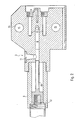
- the drawing stages 1 according to FIGS. 1a and 1b each comprise a rough stone holder 2, a pressure chamber 3 and a die holder 4 with a drawing die, not shown.
- a known, Lubricant box shown with broken lines 5 is used to take up lubricant, which at ongoing drawing process for hydrodynamic pressure conditions in the and take care of the drawing gap.
- the composite wire 6 to be formed now passes through the lubricant box 5, the Vorsteinability 2 in the pressure chamber 3 and then to the existing in the die holder 4 Drawing die to get there the actual forming step by step to be subjected.
- the Pressure chamber 3 a laterally arranged hydraulic cylinder 12 on, which in cooperation with those shown in Fig. 2 Elements forms a pressure generating device 9.
- Sensors 17 monitor the position of a not shown in Fig. 1b Tappet to the pressure conditions in the pressure chamber 3rd to be recorded indirectly.
- the drawing die holder 4 a known die cooling 16 is provided.
- Vorsteining 2, Drucksch 3, Ziehsteina 4 and pressure generating device 9 form one of a base plate 18 carried unit.
- the structure of the pressure chamber is now based on the sectional view 2 explained in more detail.
- the pressure chamber 3 comprises a lateral lubricant channel 8, which leads to the wire through hole 7 of the pressure chamber 3 leads.
- a funnel-like Lubricant feed 11 is used to supply lubricant in the event of starting, starting or restarting the drawing system.
- a pressure tappet 10 is located in the pressure generating device 9 and is actuated by the hydraulic cylinder 12, i.e. moved in the direction of the wire through hole 7 of the pressure chamber 3.
- the plunger 10 is at least partially in the side Lubricant channel 8 out and builds in the pressure conditions the pressure chamber, i.e. in the pressure chamber of the wire through hole 7 on.
- the pressure chamber has 3 holes 13 for receiving of preferably electrical heating elements and a bore 14, which is used to attach a temperature sensor.
- Fitting bores 15 serve to accommodate clamping screws, not shown, around a tight, tight press connection between Pressure chamber 3 and adjacent stone holder 2 or To ensure drawing die pickup 4.
- a pressure / temperature control device not shown detected in cooperation with the sensors 17 and that in the Hole 14 located temperature sensor continuously the pressure and Temperature conditions of the pressure chambers of all drawing stages and gives the beginning as well as the when reaching predetermined values Restart of the drawing system free.
- the one mentioned Control device capable of a known per se To control die cooling.
Landscapes
- Engineering & Computer Science (AREA)
- Mechanical Engineering (AREA)
- Metal Extraction Processes (AREA)
Description
Beispielsweise wurde in der WO 96/14946 ein Verfahren und eine Vorrichtung zum Umformen oder Beschichten von strangförmigem metallischem Umformgut vorgeschlagen, wobei dort feste, halbfeste und flüssige Schmierstoffe eingesetzt werden, mit denen auf dem Umformgut eine Schmierstoffschicht erzeugt wird.
Beim erwähnten Fertigungsstillstand, dies ist auch bei optimalen Produktionsbedingungen mehrmals am Tage der Fall, bildet sich andererseits durch Abkühlprozesse ein glasartiger Pfropfen des Schmiermittels mit der Gefahr eines oben erläuterten Drahtabrisses.
Während des Ziehvorgangs werden die Druck- und Temperaturverhältnisse in jeder Druckkammer laufend überwacht, wobei mit einsetzender Erwärmung der Ziehsteine durch den Ziehvorgang die Fremdheizung der Druckkammer deaktivierbar ist.
Gemäß einer bevorzugten Ausführungsform wird in die Druckkammer jeder Ziehstufe ein Start- oder Wiederanfahrdruck im Bereich von 100 bis 130 bar eingestellt.
Weiterhin ist eine, vorzugsweise hydraulisch betätigbare Druckerzeugungseinrichtung so an der Druckkammer angeordnet, daß über eine weitere Schmiermittelaufgabe das dem Schmiermittelkanal zugeführte Schmiermittel mit einem vorgegebenen Druck in die Durchgangsbohrung bzw. den entsprechenden Druckkammerraum preßbar ist und im Zusammenwirken mit der in der Druckkammer vorgesehenen Heizeinrichtung sich ein teigigpastöser Zustand des Schmiermittels einstellt.
Letztendlich dient die Druck/Temperatur-Regeleinrichtung der erfindungsgemäßen Vorrichtung auch der laufenden Überwachung des Ziehvorgangs, da Druckabfälle in der Druckkammer beim kontinuierlichen Betrieb der Ziehanlage auf Unregelmäßigkeiten des Ziehvorgangs oder des Umformgutes schließen lassen.
- Fig. 1a und 1b
- je eine Seitenansicht und eine Draufsicht auf die Baueinheit Ziehstufe, umfassend Vorstein- und Ziehsteinaufnahme sowie Druckkammer, und
- Fig. 2
- eine Schnittdarstellung der Druckkammer.
- 1
- Ziehstufe
- 2
- Vorsteinaufnahme
- 3
- Druckkammer
- 4
- Ziehsteinaufnahme
- 5
- Schmiermittelkasten
- 6
- Verbunddraht
- 7
- Drahtdurchgangsbohrung in der Druckkammer
- 8
- seitlicher Schmiermittelkanal
- 9
- Druckerzeugungseinrichtung
- 10
- Druckstößel
- 11
- Schmiermittelaufgabe für Druckkammer
- 12
- Hydraulikzylinder
- 13
- Bohrungen für elektrische Heizelemente
- 14
- Bohrungen für Temperatursensor
- 15
- Paßbohrungen
- 16
- Ziehsteinkühlung
- 17
- Sensoren
- 18
- Grundplatte
Claims (7)
- Verfahren zur hydrodynamischen Ziehumformung von Schichtverbunddraht mit hochfestem Kern und weichem Mantelwerkstoff mittels schmiermittelbeaufschlagten Mehrfach-Ziehanlagen unter Verwendung einer Druckkammer, wobei vor dem Anfahren der Mehrfach-Ziehanlage unmittelbar vor dem Ziehstein jeder Ziehstufe mittels je einer vom Schichtverbunddraht durchlaufenen Druckkammer auf das dort zugeführte Zieh- und Schmiermittel und den Schichtverbunddraht ein hydrostatischer Startdruck im Ziehspalt aufgebaut wird, wobei weiterhin während des fortgesetzten kontinuierlichen Ziehens in an sich bekannter Weise durch Mitnahme von Schmiermittel sich im Ziehspalt hydrodynamische Druckverhältnisse aufbauen, dadurch gekennzeichnet, daß die Druckkammer beheizt ist, daß auch vor dem Wideranfahren ein hydrostatischer Startdruck im Ziehspalt aufgebaut wird, und daß der Startdruck für jede Ziehstufen-Druckkammer durch eine Hydraulikregelung voreingestellt und überwacht wird sowie das Vorheizen der Druckkammern auf eine vorgegebene Temperatur erfolgt und beim Erreichen eines wählbaren Druck/Temperaturbereiches aller Stufen die Freigabe des Ziehvorgangs vorgenommen wird.
- Verfahren nach Anspruch 1,
dadurch gekennzeichnet, daß
während des Ziehvorgangs Druck- und Temperatur in jeder Druckkammer laufend überwacht werden, wobei mit einsetzender Erwärmung des oder der Ziehsteine durch den Ziehvorgang die Fremdheizung deaktiviert wird. - Verfahren nach einem der vorangegangenen Ansprüche,
dadurch gekennzeichnet, daß
der Start- und Wiederanfahrdruck in den Druckkammern vor jeder Ziehstufen-Druckkammer 100 bis 130 bar beträgt. - Vorrichtung zur hydrodynamischen Ziehumformung von Schichtverbunddraht mittels schmiermittelbeaufschlagten Mehrfach-Ziehanlagen, wobei zumindest die erste ziehstufe mindestens einen Vor- und Ziehstein und eine Druckkammer umfaßt, wobei,
zwischen Vor- und Ziehstein eine mit diesen eine bauliche Einheit bildende Druckkammer (3) vorgesehen ist,
die Druckkammer (3) eine Drahtdurchgangsbohrung (7) sowie einen seitlichen Schmiermittelkanal (8) aufweist,
weiterhin eine hydraulisch betätigbare Druckerzeugungseinrichtung (9) so an der Druckkammer (3) angeordnet ist, daß das
über eine weitere Schmiermittelaufgabe (11) dem Schmiermittelkanal (8) zugeführte Schmiermittel mit vorgebbarem Druck in die Drahtdurchgangsbohrung(7) preßbar ist und im Zusammenwirken
mit einer Heizeinrichtung in einen teigig-pastösen Zustand übergeht und den Schichtverbund-Ziehdraht vor dem Einlaufen in den jeweiligen Ziehstern
umgibt, und der seitliche Schmiermittelkanal (8) einen Druckstößel (10) aufnimmt, welcher von einem Hydraulikzylinder (12) betätigbar ist, dadurch gekennzeichnet, daß jede Ziehstufe einem Vor- und Ziehstein und eine Druckkammer umfaßt, daß, am Vorstein jeweils eine Schmiermittelaufgabe angeordnet ist, daß die Heizeinrichtung in der Druckkammer vorgesehen ist, und daß die Bewegung oder Lage des Stößels (10) zum mittelbaren Feststellen der Druckverhältnisse durch Sensoren (17) überwachbar ist. - Vorrichtung nach Anspruch 4,
dadurch gekennzeichnet, daß
die Druckkammer (3) seitliche Bohrungen oder Aussparungen (13) zur Aufnahme von vorzugsweise elektrischen Heizelementen sowie eine Bohrung (14) für einen Temperatursensor aufweist. - Vorrichtung nach Anspruch 4 oder 5,
dadurch gekennzeichnet, daß
zur Bildung der baulichen Einheit die Aufnahmen (2; 4) von Vorund Ziehstein sowie die Druckkammer (3) in Ziehrichtung verlaufende Paßbohrungen (15) zur Führung von Spann- und Befestigungsbolzen umfassen. - Vorrichtung nach einem der Ansprüche 4 bis 6, gekennzeichnet durch
eine Druck/Temperatur-Regeleinrichtung, welche die Druck- und Temperaturverhältnisse aller Druckkammern in den Ziehstufen-Druckkammern überwacht und den Beginn sowie das Wiederanfahren der Ziehanlage freigibt und entsprechend vorgebbarer Parameter eine an sich bekannte Ziehsteinkühlung steuert.
Applications Claiming Priority (5)
| Application Number | Priority Date | Filing Date | Title |
|---|---|---|---|
| DE19804016 | 1998-02-02 | ||
| DE19804016 | 1998-02-02 | ||
| DE19810342 | 1998-03-10 | ||
| DE19810342A DE19810342C2 (de) | 1998-02-02 | 1998-03-10 | Verfahren zur hydrodynamischen Ziehumformung von Schichtverbunddraht sowie Mehrfach-Ziehanlage |
| PCT/EP1999/000680 WO1999038625A1 (de) | 1998-02-02 | 1999-02-02 | Verfahren und vorrichtung zur hydrodynamischen ziehumformung von schichtverbunddraht mittels schmiermittelbeaufschlagten mehrfach-ziehanlagen |
Publications (2)
| Publication Number | Publication Date |
|---|---|
| EP1053064A1 EP1053064A1 (de) | 2000-11-22 |
| EP1053064B1 true EP1053064B1 (de) | 2002-05-08 |
Family
ID=26043534
Family Applications (1)
| Application Number | Title | Priority Date | Filing Date |
|---|---|---|---|
| EP99907481A Expired - Lifetime EP1053064B1 (de) | 1998-02-02 | 1999-02-02 | Verfahren und vorrichtung zur hydrodynamischen ziehumformung von schichtverbunddraht mittels schmiermittelbeaufschlagten mehrfach-ziehanlagen |
Country Status (5)
| Country | Link |
|---|---|
| EP (1) | EP1053064B1 (de) |
| JP (1) | JP3326499B2 (de) |
| AT (1) | ATE217218T1 (de) |
| CA (1) | CA2318831A1 (de) |
| WO (1) | WO1999038625A1 (de) |
Families Citing this family (2)
| Publication number | Priority date | Publication date | Assignee | Title |
|---|---|---|---|---|
| CN116984404B (zh) * | 2023-07-28 | 2024-04-26 | 浙江创特新材科技有限公司 | 可移动的多段细钨丝加热模块及高强度细钨丝拉丝设备 |
| CN120394599B (zh) * | 2025-07-03 | 2026-03-31 | 山西森鼎立设备制造有限公司 | 一种具有冷却功能的直驱式极细线拉丝机及方法 |
Family Cites Families (7)
| Publication number | Priority date | Publication date | Assignee | Title |
|---|---|---|---|---|
| US3413832A (en) * | 1965-07-27 | 1968-12-03 | Nat Standard Co | Wire drawing method |
| US3641795A (en) | 1969-12-24 | 1972-02-15 | Bethlehem Steel Corp | Method and apparatus for wire drawing with pressure dies |
| AT353737B (de) * | 1976-09-16 | 1979-11-26 | Langenecker Bertwin Dr | Verfahren und vorrichtung zum ziehen von draehten, stangen, rohren u.dgl. |
| DE2967068D1 (en) * | 1978-12-21 | 1984-07-26 | Akad Wissenschaften Ddr | Device for applying a lubricant to a metallic plastically deformable part |
| AT383513B (de) * | 1979-08-29 | 1987-07-10 | Uralsky Inst Chernykh Metall | Ziehverfahren mit hydrodynamischer schmierung |
| BG41686A1 (en) * | 1984-12-17 | 1987-08-14 | Petkov | Device for drawing of wire |
| US5865052A (en) * | 1994-11-11 | 1999-02-02 | Ecoform Umformtechnik Gmbh | Method and device for forming and/or coating wire-shaped metal material |
-
1999
- 1999-02-02 CA CA002318831A patent/CA2318831A1/en not_active Abandoned
- 1999-02-02 EP EP99907481A patent/EP1053064B1/de not_active Expired - Lifetime
- 1999-02-02 AT AT99907481T patent/ATE217218T1/de not_active IP Right Cessation
- 1999-02-02 WO PCT/EP1999/000680 patent/WO1999038625A1/de not_active Ceased
- 1999-02-02 JP JP2000529908A patent/JP3326499B2/ja not_active Expired - Fee Related
Also Published As
| Publication number | Publication date |
|---|---|
| JP3326499B2 (ja) | 2002-09-24 |
| CA2318831A1 (en) | 1999-08-05 |
| ATE217218T1 (de) | 2002-05-15 |
| EP1053064A1 (de) | 2000-11-22 |
| WO1999038625A1 (de) | 1999-08-05 |
| JP2002501827A (ja) | 2002-01-22 |
Similar Documents
| Publication | Publication Date | Title |
|---|---|---|
| DE3886979T2 (de) | Stanzvorrichtung für dünne Platten und in der Vorrichtung verwendete Stanzeinheiten. | |
| DE69203839T2 (de) | Funkenerosionbohrvorrichtung. | |
| DE3104032C2 (de) | ||
| EP1003616B1 (de) | Vorrichtung und verfahren zum verformen, insbesondere zum kaltverformen, von werkstücken | |
| EP1500451B1 (de) | Verfahren und Vorrichtung zum Entgraten von Rohren | |
| DE3129716A1 (de) | Automatische drahteinstell- oder -wiedereinstellverfahren und -vorrichtung in einer durchlaufdraht-elektroerosionsmaschine | |
| DE10010197A1 (de) | Mechanische Presse mit einer Durchbiegungsausgleichseinrichtung | |
| DE2415619A1 (de) | Schneidschrauben | |
| EP1385664B1 (de) | Verfahren und vorrichtung zum bearbeiten von ringartigen werkstücken | |
| DE202014105434U1 (de) | Pressschweißvorrichtung | |
| EP1053064B1 (de) | Verfahren und vorrichtung zur hydrodynamischen ziehumformung von schichtverbunddraht mittels schmiermittelbeaufschlagten mehrfach-ziehanlagen | |
| DE4401674A1 (de) | Verfahren sowie Vorrichtung zum Lochen von Werkstücken | |
| DE69224366T2 (de) | Verfahren zum Kontrollieren des Geräusches eines Stanzverfahrens und Einrichtung zum Stanzen eines Werkstücks | |
| WO2006133991A1 (de) | Vorrichtung und verfahren zur überwachung eines fertigungsverfahrens zur herstellung einer durchgangsbohrung | |
| DE3206501C1 (de) | Verfahren und Auszieheinrichtung zum Horizontalstranggiessen von Metall,insbesondere von Stahl | |
| DE10196821T5 (de) | Drahterodierverfahren und Vorrichtung | |
| EP0037485A1 (de) | Metallstrangpresse mit einer mit dem Aufnehmerhalter verbundenen Vorrichtung zum Abtrennen des Pressrestes und zum Auswechseln von Matrizen | |
| DE19810342C2 (de) | Verfahren zur hydrodynamischen Ziehumformung von Schichtverbunddraht sowie Mehrfach-Ziehanlage | |
| EP3010709B1 (de) | Verfahren zum verwölben des maschinenbetts und/oder des pressenstössels einer stanzpresse sowie stanzpresse | |
| EP2839893A1 (de) | Verfahren zum Betreiben einer indirekten Strangpresse und indirekte Strangpresse | |
| DE3244171A1 (de) | Verfahren und vorrichtung zur erfassung einer zwischen zwei gegeneinander bewegbaren maschinenteilen auftretenden kraft | |
| DE2424005A1 (de) | Verfahren zum entfernen eines dorns aus einem loch-walzwerk sowie entsprechend ausgebildetes walzwerk | |
| DE102018112193B4 (de) | Verfahren zur Herstellung einer Nietverbindung | |
| EP3357620A1 (de) | Verfahren und vorrichtung zum ultraschallverbinden von fügepartnern, insbesondere elektrischen leitern | |
| DE2114734A1 (de) | Gehartete und selektiv angelassene Nadel |
Legal Events
| Date | Code | Title | Description |
|---|---|---|---|
| PUAI | Public reference made under article 153(3) epc to a published international application that has entered the european phase |
Free format text: ORIGINAL CODE: 0009012 |
|
| 17P | Request for examination filed |
Effective date: 20000727 |
|
| AK | Designated contracting states |
Kind code of ref document: A1 Designated state(s): AT BE CH DE DK ES FI FR GB GR IT LI LU NL PT SE |
|
| GRAG | Despatch of communication of intention to grant |
Free format text: ORIGINAL CODE: EPIDOS AGRA |
|
| 17Q | First examination report despatched |
Effective date: 20010619 |
|
| GRAG | Despatch of communication of intention to grant |
Free format text: ORIGINAL CODE: EPIDOS AGRA |
|
| GRAH | Despatch of communication of intention to grant a patent |
Free format text: ORIGINAL CODE: EPIDOS IGRA |
|
| REG | Reference to a national code |
Ref country code: GB Ref legal event code: IF02 |
|
| GRAH | Despatch of communication of intention to grant a patent |
Free format text: ORIGINAL CODE: EPIDOS IGRA |
|
| GRAA | (expected) grant |
Free format text: ORIGINAL CODE: 0009210 |
|
| AK | Designated contracting states |
Kind code of ref document: B1 Designated state(s): AT BE CH DE DK ES FI FR GB GR IT LI LU NL PT SE |
|
| PG25 | Lapsed in a contracting state [announced via postgrant information from national office to epo] |
Ref country code: NL Free format text: LAPSE BECAUSE OF FAILURE TO SUBMIT A TRANSLATION OF THE DESCRIPTION OR TO PAY THE FEE WITHIN THE PRESCRIBED TIME-LIMIT Effective date: 20020508 Ref country code: GR Free format text: LAPSE BECAUSE OF FAILURE TO SUBMIT A TRANSLATION OF THE DESCRIPTION OR TO PAY THE FEE WITHIN THE PRESCRIBED TIME-LIMIT Effective date: 20020508 Ref country code: GB Free format text: LAPSE BECAUSE OF FAILURE TO SUBMIT A TRANSLATION OF THE DESCRIPTION OR TO PAY THE FEE WITHIN THE PRESCRIBED TIME-LIMIT Effective date: 20020508 Ref country code: FR Free format text: LAPSE BECAUSE OF FAILURE TO SUBMIT A TRANSLATION OF THE DESCRIPTION OR TO PAY THE FEE WITHIN THE PRESCRIBED TIME-LIMIT Effective date: 20020508 Ref country code: FI Free format text: LAPSE BECAUSE OF FAILURE TO SUBMIT A TRANSLATION OF THE DESCRIPTION OR TO PAY THE FEE WITHIN THE PRESCRIBED TIME-LIMIT Effective date: 20020508 |
|
| REF | Corresponds to: |
Ref document number: 217218 Country of ref document: AT Date of ref document: 20020515 Kind code of ref document: T |
|
| REG | Reference to a national code |
Ref country code: CH Ref legal event code: EP |
|
| REF | Corresponds to: |
Ref document number: 59901393 Country of ref document: DE Date of ref document: 20020613 |
|
| PG25 | Lapsed in a contracting state [announced via postgrant information from national office to epo] |
Ref country code: SE Free format text: LAPSE BECAUSE OF FAILURE TO SUBMIT A TRANSLATION OF THE DESCRIPTION OR TO PAY THE FEE WITHIN THE PRESCRIBED TIME-LIMIT Effective date: 20020808 Ref country code: PT Free format text: LAPSE BECAUSE OF FAILURE TO SUBMIT A TRANSLATION OF THE DESCRIPTION OR TO PAY THE FEE WITHIN THE PRESCRIBED TIME-LIMIT Effective date: 20020808 Ref country code: DK Free format text: LAPSE BECAUSE OF FAILURE TO SUBMIT A TRANSLATION OF THE DESCRIPTION OR TO PAY THE FEE WITHIN THE PRESCRIBED TIME-LIMIT Effective date: 20020808 |
|
| NLV1 | Nl: lapsed or annulled due to failure to fulfill the requirements of art. 29p and 29m of the patents act | ||
| GBV | Gb: ep patent (uk) treated as always having been void in accordance with gb section 77(7)/1977 [no translation filed] |
Effective date: 20020508 |
|
| PG25 | Lapsed in a contracting state [announced via postgrant information from national office to epo] |
Ref country code: ES Free format text: LAPSE BECAUSE OF FAILURE TO SUBMIT A TRANSLATION OF THE DESCRIPTION OR TO PAY THE FEE WITHIN THE PRESCRIBED TIME-LIMIT Effective date: 20021128 |
|
| EN | Fr: translation not filed | ||
| PG25 | Lapsed in a contracting state [announced via postgrant information from national office to epo] |
Ref country code: LU Free format text: LAPSE BECAUSE OF NON-PAYMENT OF DUE FEES Effective date: 20030202 Ref country code: AT Free format text: LAPSE BECAUSE OF NON-PAYMENT OF DUE FEES Effective date: 20030202 |
|
| PG25 | Lapsed in a contracting state [announced via postgrant information from national office to epo] |
Ref country code: LI Free format text: LAPSE BECAUSE OF NON-PAYMENT OF DUE FEES Effective date: 20030228 Ref country code: CH Free format text: LAPSE BECAUSE OF NON-PAYMENT OF DUE FEES Effective date: 20030228 Ref country code: BE Free format text: LAPSE BECAUSE OF NON-PAYMENT OF DUE FEES Effective date: 20030228 |
|
| PLBE | No opposition filed within time limit |
Free format text: ORIGINAL CODE: 0009261 |
|
| STAA | Information on the status of an ep patent application or granted ep patent |
Free format text: STATUS: NO OPPOSITION FILED WITHIN TIME LIMIT |
|
| 26N | No opposition filed |
Effective date: 20030211 |
|
| PG25 | Lapsed in a contracting state [announced via postgrant information from national office to epo] |
Ref country code: DE Free format text: LAPSE BECAUSE OF NON-PAYMENT OF DUE FEES Effective date: 20030902 |
|
| REG | Reference to a national code |
Ref country code: CH Ref legal event code: PL |
|
| PG25 | Lapsed in a contracting state [announced via postgrant information from national office to epo] |
Ref country code: IT Free format text: LAPSE BECAUSE OF NON-PAYMENT OF DUE FEES Effective date: 20050202 |