EP1054386A2 - Vibration damping washer assembly and method of attaching the same to heat insulating plate - Google Patents
Vibration damping washer assembly and method of attaching the same to heat insulating plate Download PDFInfo
- Publication number
- EP1054386A2 EP1054386A2 EP00110720A EP00110720A EP1054386A2 EP 1054386 A2 EP1054386 A2 EP 1054386A2 EP 00110720 A EP00110720 A EP 00110720A EP 00110720 A EP00110720 A EP 00110720A EP 1054386 A2 EP1054386 A2 EP 1054386A2
- Authority
- EP
- European Patent Office
- Prior art keywords
- male
- female
- sleeve
- washer
- heat insulating
- Prior art date
- Legal status (The legal status is an assumption and is not a legal conclusion. Google has not performed a legal analysis and makes no representation as to the accuracy of the status listed.)
- Granted
Links
Images




Classifications
-
- G—PHYSICS
- G10—MUSICAL INSTRUMENTS; ACOUSTICS
- G10K—SOUND-PRODUCING DEVICES; METHODS OR DEVICES FOR PROTECTING AGAINST, OR FOR DAMPING, NOISE OR OTHER ACOUSTIC WAVES IN GENERAL; ACOUSTICS NOT OTHERWISE PROVIDED FOR
- G10K11/00—Methods or devices for transmitting, conducting or directing sound in general; Methods or devices for protecting against, or for damping, noise or other acoustic waves in general
- G10K11/16—Methods or devices for protecting against, or for damping, noise or other acoustic waves in general
- G10K11/162—Selection of materials
- G10K11/168—Plural layers of different materials, e.g. sandwiches
-
- F—MECHANICAL ENGINEERING; LIGHTING; HEATING; WEAPONS; BLASTING
- F16—ENGINEERING ELEMENTS AND UNITS; GENERAL MEASURES FOR PRODUCING AND MAINTAINING EFFECTIVE FUNCTIONING OF MACHINES OR INSTALLATIONS; THERMAL INSULATION IN GENERAL
- F16F—SPRINGS; SHOCK-ABSORBERS; MEANS FOR DAMPING VIBRATION
- F16F1/00—Springs
- F16F1/36—Springs made of rubber or other material having high internal friction, e.g. thermoplastic elastomers
- F16F1/362—Springs made of rubber or other material having high internal friction, e.g. thermoplastic elastomers made of steel wool, compressed hair, woven or non-woven textile, or like materials
-
- B—PERFORMING OPERATIONS; TRANSPORTING
- B60—VEHICLES IN GENERAL
- B60G—VEHICLE SUSPENSION ARRANGEMENTS
- B60G2204/00—Indexing codes related to suspensions per se or to auxiliary parts
- B60G2204/40—Auxiliary suspension parts; Adjustment of suspensions
- B60G2204/41—Elastic mounts, e.g. bushings
-
- B—PERFORMING OPERATIONS; TRANSPORTING
- B60—VEHICLES IN GENERAL
- B60G—VEHICLE SUSPENSION ARRANGEMENTS
- B60G2204/00—Indexing codes related to suspensions per se or to auxiliary parts
- B60G2204/40—Auxiliary suspension parts; Adjustment of suspensions
- B60G2204/44—Centering or positioning means
Definitions
- the present invention relates to a vibration floating washer assembly and a method of attaching a vibration floating washer to a heat insulating plate. More particularly to a vibration floating washer assembly for vibration isolation and a method of attaching a vibration floating washer for vibration isolation to a heat insulating plate which is attached to a heat generating source in an automobile.
- a heat insulating plate 5 is arranged with a vibration floating washer structure by using a washer 1 with a sleeve, a pair of metallic cushioning materials 2, a washer 3, and an attaching bolt 4.
- the heat insulating plate 5 is first placed between the pair of metallic cushioning plates 2 arranged around a peripheral edge portion of an attaching-bolt insertion hole 6 in the heat insulating plate 5.
- the washer 3 is then placed on one side of the cushioning material 2, and a sleeve 7 of the washer 1 with a sleeve is inserted in the insertion hole 6 from the opposite side of the insertion hole 6.
- the present invention is aimed at overcoming the above-described problems, and is characterized by attaching in advance a washer with a sleeve, including a male washer and a female washer, to an inner side and a peripheral edge portion of an attaching-bolt insertion hole in a heat insulating plate with a metallic cushioning material placed therebetween.
- a primary object of the present invention is to simplify the operation of attaching the heat insulating plate to a supporting portion to be attached to.
- a method of attaching a vibration floating washer with a sleeve to an inner side and a peripheral edge portion of an attaching-bolt insertion hole in a heat insulating plate with a metallic cushioning material plated therebetween characterized in that the cushioning material is disposed on the inner side the peripheral edge portion of the attaching-bolt insertion hole, that a male sleeve of a male washer and a female sleeve of a female washer are respectively inserted into the bolt insertion hole from both sides of the heat insulating plate, the male washer and the female washer constituting the vibration floating washer with a sleeve, and that the male washer and the female washer are fitted and fixed to each other by means of fitting means provided on at least one of the male sleeve and the female sleeve while the heat insulating plate is maintained in a state of noncontact with both the male washer and the female washer.
- the metallic cushioning material comprises a male cushioning material and a female cushioning material
- the male cushioning material has a projecting cross-sectional shape with an axially projecting portion formed thereon
- the female cushioning material has a recessed cross-sectional shape with an axially recessed portion formed therein, both the male cushioning material and the female cushioning material having respective through holes through which the male and female sleeves of the vibration floating washer with a sleeve are passed.
- the metallic cushioning material is molded by compression molding an SUS mesh.
- a vibration floating washer assembly for being attached to a heat insulating plate including an attaching-bolt insertion hole.
- the washer assembly comprising: a vibration floating washer with a sleeve and a metallic damping element placed between the vibration floating washer.
- the vibration floating washer includes a male washer including a male sleeve and a female washer including a female sleeve. At least one of the male and female sleeves includes a fitting portion provided thereon so that the heat insulating plate is maintained in a state of noncontact with both the male and female washers.
- the vibration floating washer with a sleeve in which the male washer and the female washer can be fitted and fixed to each other by one of the fitting means, is attached and fixed, in advance, to the inner side and the peripheral edge portion of the attaching-bolt insertion hole in the heat insulating plate with the metallic cushioning material placed therebetween. Accordingly, it is possible to simplify the operation of attaching the heat insulating plate to the supporting portion to be attached to. Further, it is possible to reduce the vibration and facilitate the positional alignment between the attaching bolt and the bolt hole in the supporting portion.
- Fig. 1 is an explanatory exploded view illustrating a vibration floating washer assembly and an attaching method of the present invention.
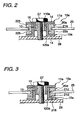
- Fig. 2 is an explanatory vertical cross-sectional view illustrating the state of attachment by the attaching method shown in Fig. 1.
- Fig. 3 is an explanatory vertical cross-sectional view illustrating the state of attachment using a different metallic cushioning material.
- Figs. 4A and 4B are explanatory diagrams illustrating one example of a vibration floating washer with a sleeve
- Fig. 4C is an explanatory diagrams illustrating another example of a male sleeve of a vibration floating washer with a sleeve.
- Figs. 1 is an explanatory exploded view illustrating a vibration floating washer assembly and an attaching method of the present invention.
- Fig. 2 is an explanatory vertical cross-sectional view illustrating the state of attachment by the attaching method shown in Fig. 1.
- Fig. 3 is an explanatory vertical cross-
- FIG. 5A to 5E are explanatory vertical cross-sectional views illustrating other examples of the vibration floating washer with a sleeve.
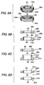
- FIG. 6A and 6B to 6D are an exploded perspective view and exploded vertical cross-sectional views illustrating examples of the metallic cushioning material, respectively.
- Figs. 4A and 4B show one example of the vibration floating washer with a sleeve, in which Fig. 4A is an exploded explanatory view, and Fig. 4B is an explanatory vertical cross-sectional view illustrating an assembled state.
- Fig. 4C is an explanatory diagrams illustrating another example of a male sleeve of a vibration floating washer with a sleeve.
- a vibration floating washer 10a with a sleeve includes a male washer 11a and a female washer 12a.
- the vibration floating washer 10a with a sleeve is formed in which both sleeves 110a and 120a are fitted and fixed together by a fitting portion 13 provided on the outer periphery of the male sleeve 110a.
- the aforementioned male sleeve 110a has an outside diameter smaller than the inside diameter of the female sleeve 120a.
- an annular protrusion 130 whose outside diameter is slightly larger than the inside diameter of the female sleeve 120a is formed on the outer periphery of the male sleeve 110a. For this reason, if the male sleeve 110a is inserted in the female sleeve 120a with a fixed pressing force, the vibration floating washer 10a with a sleeve in which the two members are firmly fitted together by the annular protrusion 130 is formed.
- annular protrusion 130 Only one annular protrusion 130 is provided in the illustrated case, but two or more annular protrusions 130 may be provided, or a plurality of discontinuous protrusions may be formed. Thus, it is possible to use an arbitrary fitting shapes such as inclined discontinuous protrusions or regular or irregular protrusions.
- reference numeral 14 denotes a collar portion
- numeral 15 denotes a bolt hole.
- a fitting portion 13 is provided as a circular protrusion 140 on the periphery of each hole 150.
- the circular protrusion 140 has functions similar to ones of the annular protrusion 130 shown in Figs. 4A and 4C.
- Figs. 5A to 5E illustrate examples different from the above-described vibration floating washer 10a with a sleeve. Although their basic construction is the same, there are differences in specific modes.
- a vibration floating washer 10b with a sleeve shown in Fig. 5A has two annular protrusions 130 formed on an outer periphery of a male sleeve 110b.
- a vibration floating washer 10c with a sleeve shown in Fig. 5B has a single annular protrusion 130 formed on an inner periphery of a female sleeve 120c.
- a vibration floating washer 10d with a sleeve shown in Fig. 5C has the annular protrusion 130 formed on an upper end of the outer periphery of a female sleeve 120d.
- the opening edge side of a male sleeve 110e is formed as a gently inclined surface 112, and the arrangement provided is such that both sleeves 110e and 120e are rubbed against each other so as to be fitted and fixed together.
- 5E is formed of a metallic material having a spring characteristic, and the arrangement provided is such that a male sleeve 110f having a slit 113 in the axial direction is press-fitted to a female sleeve 120f so as to be fitted and fixed together.
- FIGs. 6A to 6D show metallic cushioning materials 20a to 20d of the respective examples.
- the metallic cushioning material 20a shown in Fig. 6A includes a male 21a and a female 22a which are molded by compression-molding an SUS metal mesh and are both annular in shape.
- the male cushioning material 21a has a projecting cross-sectional shape with an axially projecting portion 210 formed thereon, while the female cushioning material 22a has a recessed cross-sectional shape with an axially recessed portion 220 formed therein.
- Both the male cushioning material 21a and the female cushioning material 22a have respective through holes 23 through which the sleeves 110a, 110b, ... and 120a, 120b, ... of each of the above-described vibration floating washers 10a, 10b, ... with a sleeve are passed.
- a heat insulating plate 25 is clamped between a distal shoulder portion 225 of the nonprojecting portion of the male cushioning material 21a and a distal end portion 226 of the female cushioning material 22a, is supported in noncontact with the vibration floating washer 10a with a sleeve through the cushioning material 20a.
- This SUS metal mesh is molded under the following conditions.
- the metallic cushioning material 20b shown in Fig. 6B is similarly comprised of a male cushioning material 21b and a female cushioning material 22b.
- the male cushioning material 21b is formed as a ring 212 whose inner peripheral upper end side on the through hole 23 side is formed as an edged portion 211, while the female cushioning material 22b has a ring 222 whose inner peripheral lower end on the through hole 23 side is formed as a notched portion 221.
- the arrangement provided is such that, at the time of use, the inner peripheral edge of the heat insulating plate is clamped by an upper surface 218 of the ring 212 and a lower surface 228 of the ring 222.
- the metallic cushioning material 20c shown in Fig. 6C is comprised of a male cushioning material 21c and a female cushioning material 22c.
- the male cushioning material 21c is formed as a projecting portion 214 having an axially projecting portion 213 in its cross-sectional shape, while the female cushioning material 22c corresponding thereto is formed as a ring 223 whose cross-sectional shape is rectangular.
- the arrangement provided is such that, at the time of use, the projecting portion 213 of the male cushioning material 21c is fitted to the inner side of the ring 223 of the female cushioning material 22c, and the inner peripheral portion of the heat insulating plate is clamped by an upper surface 231, which forms a shoulder portion at a rear end of the projecting portion 213 of the male cushioning material 21c, and a lower surface 232 of the ring 223 of the female cushioning material 22c.
- the metallic cushioning material 20d shown in Fig. 6D is comprised of a pair of cushioning materials 21d, each having a flared cross-sectional portion 215 whose through hole 23 side has a larger thickness.
- the arrangement provided is such that, at the time of use, the peripheral edge portion of the heat insulating plate is clamped in a space 216 which is formed between the pair of flared cross-sectional portions 215 when the two cushioning materials 21d are superposed on top of each other to abut against each other.
- Fig. 1 shows an example in which the vibration floating washer 10a (11a, 12a) with a sleeve and the metallic cushioning material 20a (21a, 22a) are used.
- the projecting portion 210 of the male cushioning material 21a of the projecting shape is inserted in an attaching-bolt insertion hole 26 in the heat insulating plate 25, and the recessed portion 220 of the female cushioning material 22a is fitted to the projecting portion 210 from the opposite side of the heat insulating plate 25.
- the respective male and female sleeves 110a and 120a of the male washer 11a and the female washer 12a are inserted into the bolt insertion hole 26 from both sides thereof.
- the male sleeve 110a is then inserted into the female sleeve 120a, and the two members are fitted and fixed together by the fitting portion 13 by applying a pressing force thereto. Consequently, the heat insulating plate 25 is obtained to which the male and female washers 11a and 12a are fixed in the attaching-bolt insertion hole 26 with the male and female cushioning materials 21a and 22a placed therebetween.
- Reference numeral 27 denotes a fastening bolt.
- Fig. 2 shows an example of use in which the vibration floating washer 10a with a sleeve and the metallic cushioning material 20a are used, and the heat insulating plate 25 is attached to the supporting portion 28 to be attached to by means of the fastening bolt 27 in the vibration floating structure.
- Fig. 3 shows an example of use in which the vibration floating washer 10a with a sleeve and the metallic cushioning material 20d are used, and the inner side and the peripheral edge portion of the bolt inserting hole 26 of the heat insulating plate 25 are clamped in the space 216 formed by the flared cross-sectional portions 215 of the pair of cushioning materials 21d, so as to attach the vibration floating washer 10a with a sleeve in the vibration floating structure.
- the vibration floating washer with a sleeve is attached and fixed, in advance, to the attaching-bolt insertion hole in the heat insulating plate with the metallic cushioning material placed therebetween, it is possible to overcome the difficulties in the operation in the conventional assembly line and attain the simplification of the attaching operation. Further, it is possible to overcome other difficulties including the positioning of the bolt.
- vibration floating washer with a sleeve and the metallic cushioning material which are used have simple construction, and can be provided at low cost.
- the present invention is based on Japanese Patent Application No. Hei. 11-139230 which is incorporated herein by reference.
Landscapes
- Engineering & Computer Science (AREA)
- General Engineering & Computer Science (AREA)
- Textile Engineering (AREA)
- Mechanical Engineering (AREA)
- Physics & Mathematics (AREA)
- Acoustics & Sound (AREA)
- Multimedia (AREA)
- Vibration Prevention Devices (AREA)
- Springs (AREA)
- Cooling, Air Intake And Gas Exhaust, And Fuel Tank Arrangements In Propulsion Units (AREA)
- Connection Of Plates (AREA)
- Bolts, Nuts, And Washers (AREA)
Abstract
Description
- Material :
- a stainless steel wire of SUS 316, SUS 310S, SUS 301, or SUS 304
- Wire diameter :
- 0.05 - 0.35 mm
- Weaving style :
- knitting in a unit of 1 - 5 strand(s) of the wire of the aforementioned diameter
- Density :
- 0.5 - 0.3 g/cm3
- Spring constant K :
- 0.01 - 10 kgf/mm Preferably, 0.1 - 2.0 kgf/mm
Claims (10)
- A method of attaching a vibration floating washer with a sleeve to a heat insulating plate including an attaching-bolt insertion hole, said vibration floating washer being attached with a metallic damping element placed therebetween, said vibration floating washer including a male washer and a female washer, said male washer and said female washer respectively including a male sleeve and a female sleeve, at least one of said male sleeve and said female sleeve including a fitting portion provided thereon, said method comprising;disposing said cushioning element on the inner side and the peripheral edge portion of the attaching-bolt insertion hole;inserting said male sleeve of said male washer and said female sleeve of said female washer respectively into the bolt insertion hole from both sides of the heat insulating plate; andfitting and fixing said male washer and said female washers to each other with said fitting portion provided on at least one of said male sleeve and said female sleeve so that said heat insulating plate is maintained in a state of noncontact with both said male washer and said female washer.
- The method of attaching a vibration floating washer to a heat insulating plate according to claim 1,
wherein said fitting portion provided on at least one of said male sleeve and said female sleeve is one of an annular projecting portion and a discontinuous projecting portion. - The method of attaching a vibration floating washer to a heat insulating plate according to claim 1,
wherein said metallic damping element includes a male cushioning portion and a female cushioning portion,
wherein said male cushioning portion has a projecting cross-sectional shape with an axially projecting portion formed thereon, and said female cushioning portion has a recessed cross-sectional shape with an axially recessed portion formed therein, and
wherein both said male cushioning element and said female cushioning element have respective through holes through which said male and female sleeves of said vibration floating washer are passed. - The method of attaching a vibration floating washer to a heat insulating plate according to claim 1,
wherein said metallic damping element is molded by compression molding an SUS mesh. - A vibration floating washer assembly for being attached to a heat insulating plate including an attaching-bolt insertion hole, said washer assembly comprising:a vibration floating washer with a sleeve, includinga male washer including a male sleeve anda female washer including a female sleeve; anda metallic damping element placed between said vibration floating washer,
wherein at least one of said male sleeve and female sleeve include a fitting portion provided thereon so that the heat insulating plate is maintained in a state of noncontact with both said male and female washers. - The vibration floating washer assembly according to claim 5,
wherein said fitting portion provided on at least one of said male sleeve and said female sleeve is an annular projecting portion and a discontinuous projecting portion. - The vibration floating washer assembly according to claim 5,
wherein said fitting portion provided on at least one of said male sleeve and said female sleeve is a discontinuous projecting portion. - The vibration floating washer assembly according to claim 7,
wherein said male sleeve includes holes on its surface, and said discontinuous projecting portion is circular protrusions on a periphery of each hole thereon. - The vibration floating washer assembly according to claim 5,
wherein said metallic damping element includes a male cushioning portion and a female cushioning portion,
wherein said male cushioning portion has a projecting cross-sectional shape with an axially projecting portion formed thereon, and said female cushioning portion has a recessed cross-sectional shape with an axially recessed portion formed therein, and
wherein both said male cushioning element and said female cushioning element have respective through holes through which said male and female sleeves of said vibration floating washer are passed. - The vibration floating washer assembly according to claim 5,
wherein said metallic damping element is molded by compression molding an SUS mesh.
Applications Claiming Priority (2)
| Application Number | Priority Date | Filing Date | Title |
|---|---|---|---|
| JP13923099A JP3490927B2 (en) | 1999-05-19 | 1999-05-19 | How to attach a vibrating floating washer to the heat shield |
| JP13923099 | 1999-05-19 |
Publications (3)
| Publication Number | Publication Date |
|---|---|
| EP1054386A2 true EP1054386A2 (en) | 2000-11-22 |
| EP1054386A3 EP1054386A3 (en) | 2001-07-04 |
| EP1054386B1 EP1054386B1 (en) | 2015-04-08 |
Family
ID=15240521
Family Applications (1)
| Application Number | Title | Priority Date | Filing Date |
|---|---|---|---|
| EP00110720.0A Expired - Lifetime EP1054386B1 (en) | 1999-05-19 | 2000-05-19 | Vibration damping washer assembly and method of attaching the same to heat insulating plate |
Country Status (3)
| Country | Link |
|---|---|
| US (1) | US6328513B1 (en) |
| EP (1) | EP1054386B1 (en) |
| JP (1) | JP3490927B2 (en) |
Cited By (8)
| Publication number | Priority date | Publication date | Assignee | Title |
|---|---|---|---|---|
| WO2009133526A3 (en) * | 2008-04-29 | 2010-05-20 | Compact-Habit, S. L. | Joining element between modules for constructions |
| EP2390120A1 (en) * | 2010-05-26 | 2011-11-30 | Continental Teves AG & Co. oHG | Acoustic decoupling in vehicle chassis |
| CN101578926B (en) * | 2006-10-16 | 2012-08-22 | 朗姆研究公司 | Components of plasma processing plants |
| EP2980437A1 (en) * | 2014-08-01 | 2016-02-03 | Stop-Choc Schwingungstechnik GmbH & Co. KG | Vibration damping fastening system |
| EP2419308A4 (en) * | 2009-04-13 | 2017-10-18 | Hydro-Aire Inc. Subsidiary of Crane Co. | Shock and vibration isolation for aircraft brake control valve |
| DE102020128549A1 (en) | 2020-10-29 | 2022-05-05 | Böllhoff Verbindungstechnik GmbH | Damping arrangement, component with damping arrangement and corresponding component connection, a manufacturing method and a connection method |
| CN116365139A (en) * | 2022-09-09 | 2023-06-30 | 国电南瑞科技股份有限公司 | Heat insulation vibration reduction device of energy storage battery module and low-heat-loss high-flexibility mounting method |
| DE102022110271A1 (en) | 2022-04-27 | 2023-11-02 | Böllhoff Verbindungstechnik GmbH | Damping arrangement, component with damping arrangement, corresponding component connection, connection method and manufacturing method |
Families Citing this family (90)
| Publication number | Priority date | Publication date | Assignee | Title |
|---|---|---|---|---|
| US7375277B1 (en) | 2000-06-26 | 2008-05-20 | Fatigue Technology, Inc. | Double flanged bushings and installation methods |
| DE10030300A1 (en) * | 2000-06-27 | 2002-01-10 | Alfa Laval Flow Gmbh | flap seal |
| JP4894102B2 (en) * | 2001-07-23 | 2012-03-14 | タカタ株式会社 | Attachment structure of cloth sheet to vehicle body |
| US20030226939A1 (en) * | 2002-06-07 | 2003-12-11 | Beck Jeremy M. | Grommet connector |
| DE10241883B4 (en) * | 2002-09-10 | 2012-06-21 | Andreas Stihl Ag & Co. | Hand-held implement with a mounting pin for an exhaust silencer |
| DE20218301U1 (en) * | 2002-11-26 | 2003-02-13 | Schwarz Verbindungssysteme GmbH, 75382 Althengstett | Vibration damper ring insert arrangement, also in connection arrangements for components |
| US6966402B2 (en) * | 2003-06-02 | 2005-11-22 | Dana Corporation | Acoustical heat shield |
| JP2005030570A (en) * | 2003-07-11 | 2005-02-03 | Nichias Corp | Anti-vibration heat shield |
| US7448652B2 (en) | 2003-07-31 | 2008-11-11 | Fatigue Technology Inc. | Tubular metal fitting expandable in a wall opening and method of installation |
| WO2005019714A2 (en) * | 2003-08-12 | 2005-03-03 | Ogg Harding Machine, Inc. | Heat shield retainer assembly |
| JP4398222B2 (en) * | 2003-10-29 | 2010-01-13 | ニチアス株式会社 | Anti-vibration heat shield |
| US7509829B2 (en) | 2005-12-28 | 2009-03-31 | Fatigue Technology, Inc. | Mandrel assembly and method of using the same |
| WO2007082077A1 (en) | 2006-01-11 | 2007-07-19 | Fatigue Technology, Inc. | Bushing kits, bearings, and methods of installation |
| US7874059B2 (en) * | 2006-01-12 | 2011-01-25 | Siemens Energy, Inc. | Attachment for ceramic matrix composite component |
| US20070210224A1 (en) * | 2006-03-09 | 2007-09-13 | Adlink Technology Inc. | Diskdrive bracket mounting structure |
| ATE536957T1 (en) | 2006-04-27 | 2011-12-15 | Fatigue Technology Inc | ALIGNMENT DEVICE AND METHOD OF USE |
| US7958766B2 (en) | 2006-06-29 | 2011-06-14 | Fatigue Technology, Inc. | Self-aligning tools and a mandrel with retention sleeve |
| DE102006037201A1 (en) * | 2006-08-09 | 2008-02-14 | Andreas Stihl Ag & Co. Kg | Hand-held implement |
| KR101468399B1 (en) | 2006-08-28 | 2014-12-03 | 퍼티구 테크놀로지 인코포레이티드 | Installation / processing systems and how to use them |
| US7682117B2 (en) * | 2006-09-27 | 2010-03-23 | Illinois Tool Works Inc. | Work piece isolating assembly |
| JP2008138690A (en) * | 2006-11-30 | 2008-06-19 | Tanashin Denki Co | Attachment mechanism for rotating component |
| DE102006060829B4 (en) * | 2006-12-22 | 2010-03-25 | Keiper Gmbh & Co. Kg | Bearing arrangement, in particular a vehicle seat |
| DE202007011491U1 (en) * | 2007-08-16 | 2007-10-18 | Acument Gmbh & Co. Ohg | Device for fastening plastic parts to a motor vehicle body |
| EP2210001B1 (en) | 2007-10-16 | 2017-08-02 | Fatigue Technology, Inc. | Expandable fastener assembly with deformed collar |
| US7908708B2 (en) * | 2008-01-22 | 2011-03-22 | Michael Steven Gelb | Surface cover with snap having a drill guide |
| EP2259884B1 (en) | 2008-03-07 | 2018-11-28 | Fatigue Technology, Inc. | Expandable member with wave inhibitor and methods of using the same |
| WO2010009442A2 (en) | 2008-07-18 | 2010-01-21 | Fatigue Technology, Inc. | Nut plate assembly and methods of using the same |
| US8393601B2 (en) * | 2008-10-04 | 2013-03-12 | Applied Concepts Aircraft Solutions, Inc. | Vibration isolation fastener insert |
| EP2356354B1 (en) * | 2008-11-28 | 2015-08-26 | Acs Industries, Inc. | Wire mesh rivet |
| US8152117B2 (en) * | 2008-12-30 | 2012-04-10 | Paul R. Gain | Adjustable bushing |
| US20100199569A1 (en) * | 2009-02-06 | 2010-08-12 | Daniel Piedade | Oversized, stress-transferring spacer for window assembly, and window assembly incorporating the same |
| FR2943856B1 (en) * | 2009-03-25 | 2011-07-22 | Labinal | SUPPORT DEVICE FOR ELECTRIC HARNESS AT THE CONVEYANCE OF A STRUCTURE |
| EP2417369B1 (en) | 2009-04-10 | 2014-04-02 | Fatigue Technology, Inc. | Installable assembly having an expandable outer member and a fastener with a mandrel |
| JP4701368B2 (en) * | 2009-08-17 | 2011-06-15 | 三和パッキング工業株式会社 | Shock absorber and metal cover |
| DE202010013507U1 (en) * | 2009-09-23 | 2011-02-10 | Reinz-Dichtungs-Gmbh | heat shield |
| US8647035B2 (en) | 2009-12-16 | 2014-02-11 | Fatigue Technology, Inc. | Modular nut plate assemblies and methods of using the same |
| AT510323B1 (en) * | 2010-09-06 | 2012-09-15 | Facc Ag | FIXING DEVICE |
| JP2012149698A (en) * | 2011-01-19 | 2012-08-09 | Sanwa Packing Kogyo Co Ltd | Collar member, shock absorber and metallic cover |
| DE202011001962U1 (en) * | 2011-01-26 | 2012-01-27 | Reinz-Dichtungs-Gmbh | heat shield |
| DE202011001961U1 (en) * | 2011-01-26 | 2012-01-27 | Reinz-Dichtungs-Gmbh | heat shield |
| US8776909B2 (en) * | 2011-02-28 | 2014-07-15 | Alan L. Johnson | Double headed hand-powered cultivator |
| WO2012167136A2 (en) | 2011-06-03 | 2012-12-06 | Fatigue Technology, Inc. | Expandable crack inhibitors and methods of using the same |
| WO2012174215A2 (en) | 2011-06-15 | 2012-12-20 | Fatigue Technology, Inc | Modular nut plates with closed nut assemblies |
| DE102011082132A1 (en) * | 2011-09-05 | 2013-03-07 | Federal-Mogul Sealing Systems Gmbh | Wärmeabschirmkörper with temperature-resistant attachment points and method for its preparation |
| US8900737B2 (en) * | 2011-09-08 | 2014-12-02 | Samsung Sdi Co., Ltd. | Energy storage system |
| US8931137B2 (en) * | 2012-01-24 | 2015-01-13 | Ra Brands, L.L.C. | Bushing for a firearm grip screw |
| EP2809482B1 (en) | 2012-01-30 | 2018-11-07 | Fatigue Technology, Inc. | Processing systems and method of operating the same |
| US9038952B2 (en) * | 2012-02-10 | 2015-05-26 | Bell Helicopter Textron Inc. | Attachment devices for rotorcraft front windshield |
| CN104470797B (en) * | 2012-07-30 | 2017-05-10 | 凯斯纽荷兰(中国)管理有限公司 | Undercarriage for a tracked work vehicle and manufacturing method thereof |
| US9140279B2 (en) | 2012-09-25 | 2015-09-22 | The Young Engineers, Inc. | Magnetic mount |
| JP5924239B2 (en) * | 2012-11-09 | 2016-05-25 | 株式会社デンソー | Anti-vibration bush and electronic device |
| JP5773975B2 (en) * | 2012-12-26 | 2015-09-02 | 本田技研工業株式会社 | Exhaust pipe cover structure for saddle-ride type vehicles |
| JP6032605B2 (en) * | 2013-02-01 | 2016-11-30 | 株式会社ユタカ技研 | Heat shield cover mounting structure for exhaust system parts |
| US9359011B2 (en) * | 2013-05-16 | 2016-06-07 | GM Global Technology Operations LLC | Attachment assembly |
| JP6156294B2 (en) * | 2013-11-22 | 2017-07-05 | トヨタ自動車株式会社 | Fastening structure |
| US9273707B2 (en) * | 2014-01-07 | 2016-03-01 | Seong Hwan Lee | Female-male combination type ornament |
| US9239210B2 (en) | 2014-04-03 | 2016-01-19 | Magpul Industries Corp. | Firearm accessory mounting interface |
| US9921029B2 (en) | 2014-01-10 | 2018-03-20 | Magpul Industries Corp. | Connector |
| ITTO20140003U1 (en) * | 2014-01-10 | 2015-07-10 | Johnson Electric Asti S R L | ELECTROVENTILATORE OF COOLING, PARTICULARLY FOR A HEAT EXCHANGER OF A MOTOR VEHICLE |
| US9239209B2 (en) | 2014-04-03 | 2016-01-19 | Magpul Industries, Corp. | Firearm accessory mounting interface |
| US9452819B2 (en) * | 2014-03-24 | 2016-09-27 | The Boeing Company | Flight control surface seal |
| CN104948654B (en) * | 2014-03-28 | 2018-11-23 | 广东松下环境系统有限公司 | Reduce noise structure |
| ITTO20140060U1 (en) * | 2014-04-17 | 2015-10-17 | Johnson Electric Asti S R L | ELECTROVENTILATORE OF COOLING, PARTICULARLY FOR A HEAT EXCHANGER OF A MOTOR VEHICLE |
| GB201408213D0 (en) * | 2014-05-09 | 2014-06-25 | Avdel Uk Ltd | Apparatus and methods for providing a threaded fixing in a crushable or brittle material |
| US9714676B2 (en) * | 2014-08-07 | 2017-07-25 | The Boeing Company | Hole-filling sleeve and washer design for bolt installation |
| CN104265830A (en) * | 2014-09-13 | 2015-01-07 | 天津齐明环保设备有限公司 | Novel damping rubber pier |
| JP6087482B1 (en) * | 2015-10-09 | 2017-03-01 | ニチアス株式会社 | Connector |
| DE102015118117A1 (en) * | 2015-10-23 | 2017-04-27 | Elringklinger Ag | Plate-like component with a plate-like component by cross-fastening device |
| DE102016106150A1 (en) * | 2016-04-05 | 2017-10-05 | Elringklinger Ag | Fastening device for a shielding part, in particular for a heat shield and shielding part comprising at least one fastening device |
| DE102016106153A1 (en) * | 2016-04-05 | 2017-10-05 | Elringklinger Ag | Shielding part, in particular heat shield, with a fastening device for fastening the shielding part to a fastening partner part |
| DE102016106151A1 (en) * | 2016-04-05 | 2017-10-05 | Elringklinger Ag | Fastening device for a shielding part for vibration-decoupling fastening of the shielding part to a fastening partner part and shielding part comprising fastening device |
| KR101737105B1 (en) * | 2016-08-18 | 2017-05-17 | (주)진영코리아 | Isolator assembly for absorbing vibration |
| CN106300878B (en) * | 2016-10-25 | 2018-11-30 | 株洲中车机电科技有限公司 | A kind of linear motor tablet installation stop device |
| DE202017103087U1 (en) * | 2017-05-22 | 2018-08-23 | Reinz-Dichtungs-Gmbh | heat shield |
| JP6872445B2 (en) | 2017-07-14 | 2021-05-19 | 本田技研工業株式会社 | Vehicle sound insulation structure |
| DE102017126241A1 (en) * | 2017-11-09 | 2019-05-09 | Man Truck & Bus Ag | Heat shield mounting |
| DE102019111078A1 (en) * | 2019-04-29 | 2020-10-29 | Böllhoff Verbindungstechnik GmbH | Fastening arrangement with a damping effect and component connection with the fastening arrangement |
| US11732724B2 (en) * | 2019-12-23 | 2023-08-22 | Hunter Fan Company | Ceiling fan blade and grommet |
| KR102179977B1 (en) * | 2020-02-06 | 2020-11-17 | 주식회사 한텍테크놀로지 | Exhaust manifold heat dissipation cover coupling device for thermal stress and vibration deflection |
| DE202020101595U1 (en) * | 2020-03-25 | 2021-06-28 | Reinz-Dichtungs-Gmbh | Decoupling element for heat shields |
| CN111706589B (en) * | 2020-05-15 | 2021-11-12 | 江苏永昊高强度螺栓有限公司 | Anti-seismic bolt |
| JP7521387B2 (en) * | 2020-11-19 | 2024-07-24 | 株式会社デンソー | Damper, mounting body, and electronic control device |
| JP7521420B2 (en) * | 2020-12-24 | 2024-07-24 | 株式会社デンソー | Damper, electronic control device, and assembly method |
| US12135051B2 (en) * | 2021-04-23 | 2024-11-05 | Illinois Tool Works Inc. | Method of retaining a sleeve with low force |
| US12173769B1 (en) * | 2021-04-28 | 2024-12-24 | LJ Avalon LLC | Vibration reducing system |
| CN113370266B (en) * | 2021-06-11 | 2022-11-22 | 上海擎朗智能科技有限公司 | Floating tray mechanism and robot |
| DE202021106327U1 (en) | 2021-11-19 | 2023-02-27 | Reinz-Dichtungs-Gmbh | Tolerance-independent movable hole reinforcement unit for a shield unit, with defined clamping when tightening the screws |
| JP7622676B2 (en) | 2022-03-09 | 2025-01-28 | 株式会社デンソー | Electrical device and manufacturing method for electrical device |
| DE102022107298B4 (en) * | 2022-03-28 | 2025-05-22 | Benteler Automobiltechnik Gmbh | Chassis component with a mount for an elastomer bearing |
| USD1048871S1 (en) * | 2022-04-25 | 2024-10-29 | Kelvin James Matthews | Fastening device |
Family Cites Families (10)
| Publication number | Priority date | Publication date | Assignee | Title |
|---|---|---|---|---|
| US3013643A (en) * | 1959-06-19 | 1961-12-19 | Goodrich Co B F | Fastener and cushioning structure utilizing the same |
| FR1519650A (en) * | 1967-01-03 | 1968-04-05 | Vibrachoc Sa | New shock absorber device for motor vehicle |
| US3622194A (en) * | 1969-12-29 | 1971-11-23 | Ford Motor Co | Motor vehicle body mount |
| DE2121677A1 (en) * | 1971-05-03 | 1972-11-16 | Continental Gummi-Werke Ag, 3000 Hannover | Elastic mount, in particular for the engine suspension in motor vehicles |
| GB1555429A (en) * | 1976-11-15 | 1979-11-07 | Caterpillar Tractor Co | Mouting grommet |
| US4445594A (en) * | 1981-10-30 | 1984-05-01 | General Motors Corporation | Disc brake noise reduction |
| FR2627821B1 (en) * | 1988-02-26 | 1990-04-06 | Valeo | ANTI-VIBRATORY FIXING DEVICE, PARTICULARLY A COAL HOLDER PLATE ON THE BEARING FLANGE OF AN ELECTRIC MOTOR |
| US5069586A (en) * | 1990-08-27 | 1991-12-03 | Casey Marion B | Self-locking two-part grommet |
| DE19716733A1 (en) | 1997-04-14 | 1998-10-15 | J & S Gmbh Werkzeugbau Stanz U | Acoustic damping cover with fixture part |
| JP3110237U (en) | 2005-02-01 | 2005-06-16 | 成肯國際實業股▲ふん▼有限公司 | The structure of the stepping foil for the seat |
-
1999
- 1999-05-19 JP JP13923099A patent/JP3490927B2/en not_active Expired - Fee Related
-
2000
- 2000-05-19 EP EP00110720.0A patent/EP1054386B1/en not_active Expired - Lifetime
- 2000-05-19 US US09/573,963 patent/US6328513B1/en not_active Expired - Lifetime
Cited By (12)
| Publication number | Priority date | Publication date | Assignee | Title |
|---|---|---|---|---|
| CN101578926B (en) * | 2006-10-16 | 2012-08-22 | 朗姆研究公司 | Components of plasma processing plants |
| WO2009133526A3 (en) * | 2008-04-29 | 2010-05-20 | Compact-Habit, S. L. | Joining element between modules for constructions |
| ES2362514A1 (en) * | 2008-04-29 | 2011-07-07 | Compact-Habit, S.L. | Joining element between modules for constructions |
| EP2419308A4 (en) * | 2009-04-13 | 2017-10-18 | Hydro-Aire Inc. Subsidiary of Crane Co. | Shock and vibration isolation for aircraft brake control valve |
| EP2390120A1 (en) * | 2010-05-26 | 2011-11-30 | Continental Teves AG & Co. oHG | Acoustic decoupling in vehicle chassis |
| EP2980437A1 (en) * | 2014-08-01 | 2016-02-03 | Stop-Choc Schwingungstechnik GmbH & Co. KG | Vibration damping fastening system |
| DE102020128549A1 (en) | 2020-10-29 | 2022-05-05 | Böllhoff Verbindungstechnik GmbH | Damping arrangement, component with damping arrangement and corresponding component connection, a manufacturing method and a connection method |
| EP3995716A1 (en) | 2020-10-29 | 2022-05-11 | Böllhoff Verbindungstechnik GmbH | Damping arrangement, component with damping arrangement and corresponding component connection, manufacturing method and connection method |
| US12258995B2 (en) | 2020-10-29 | 2025-03-25 | Böllhoff Verbindungstechnik GmbH | Damping arrangement, component with damping arrangement as well as corresponding component connection, a manufacturing method and a connecting method |
| DE102022110271A1 (en) | 2022-04-27 | 2023-11-02 | Böllhoff Verbindungstechnik GmbH | Damping arrangement, component with damping arrangement, corresponding component connection, connection method and manufacturing method |
| CN116365139A (en) * | 2022-09-09 | 2023-06-30 | 国电南瑞科技股份有限公司 | Heat insulation vibration reduction device of energy storage battery module and low-heat-loss high-flexibility mounting method |
| CN116365139B (en) * | 2022-09-09 | 2024-01-23 | 国电南瑞科技股份有限公司 | A heat insulation and vibration reduction device for energy storage battery modules and a low heat loss and high flexibility installation method |
Also Published As
| Publication number | Publication date |
|---|---|
| EP1054386B1 (en) | 2015-04-08 |
| JP3490927B2 (en) | 2004-01-26 |
| JP2000329192A (en) | 2000-11-28 |
| EP1054386A3 (en) | 2001-07-04 |
| US6328513B1 (en) | 2001-12-11 |
Similar Documents
| Publication | Publication Date | Title |
|---|---|---|
| EP1054386A2 (en) | Vibration damping washer assembly and method of attaching the same to heat insulating plate | |
| US7065963B2 (en) | Vibration and heat insulating board | |
| US6572070B2 (en) | Exhaust system hanger isolator | |
| JP2000018223A (en) | Weld stud | |
| US7155903B2 (en) | Buffer washer member and vibration and heat insulating board having the same | |
| JPS6050258A (en) | Cylinder head gasket | |
| US6685888B1 (en) | Monolith supporting structure for use in catalytic converter | |
| JPH08138944A (en) | Iron core annular coil fixture | |
| US7530146B2 (en) | Assist grip | |
| JPH01307530A (en) | Spring assembly | |
| JPH08128485A (en) | Mounting ring for hydraulic shock absorber and method for manufacturing mounting ring for hydraulic shock absorber | |
| KR200448238Y1 (en) | Band cable for fixing wire harness | |
| JP3389182B2 (en) | Speaker mounting structure | |
| JP2001115853A (en) | Supporting device for heat shielding plate | |
| JP2001323965A (en) | Vibration control device | |
| US5836624A (en) | Metal part including a spherical wall element, and an exhaust ball-coupling including such a part | |
| CN2461232Y (en) | Speaker Mounting Device | |
| JP2000087945A (en) | Combination component and its manufacture | |
| JP2775624B2 (en) | Washer with spring washer | |
| JP2019160595A (en) | Connector holding structure | |
| JP2000356138A (en) | Exhaust pipe heat shield cover mounting structure | |
| JPH0330746B2 (en) | ||
| JP2586425Y2 (en) | Muffler support for vehicle exhaust | |
| JP2562846Y2 (en) | Laminated washer seal | |
| JPH10318473A (en) | Hose band |
Legal Events
| Date | Code | Title | Description |
|---|---|---|---|
| PUAI | Public reference made under article 153(3) epc to a published international application that has entered the european phase |
Free format text: ORIGINAL CODE: 0009012 |
|
| AK | Designated contracting states |
Kind code of ref document: A2 Designated state(s): AT BE CH CY DE DK ES FI FR GB GR IE IT LI LU MC NL PT SE |
|
| AX | Request for extension of the european patent |
Free format text: AL;LT;LV;MK;RO;SI |
|
| PUAL | Search report despatched |
Free format text: ORIGINAL CODE: 0009013 |
|
| AK | Designated contracting states |
Kind code of ref document: A3 Designated state(s): AT BE CH CY DE DK ES FI FR GB GR IE IT LI LU MC NL PT SE |
|
| AX | Request for extension of the european patent |
Free format text: AL;LT;LV;MK;RO;SI |
|
| RIC1 | Information provided on ipc code assigned before grant |
Free format text: 7G 10K 11/168 A, 7F 16F 1/362 B |
|
| 17P | Request for examination filed |
Effective date: 20011010 |
|
| AKX | Designation fees paid |
Free format text: DE FR GB IT |
|
| GRAP | Despatch of communication of intention to grant a patent |
Free format text: ORIGINAL CODE: EPIDOSNIGR1 |
|
| INTG | Intention to grant announced |
Effective date: 20141030 |
|
| GRAS | Grant fee paid |
Free format text: ORIGINAL CODE: EPIDOSNIGR3 |
|
| GRAA | (expected) grant |
Free format text: ORIGINAL CODE: 0009210 |
|
| RAP1 | Party data changed (applicant data changed or rights of an application transferred) |
Owner name: NICHIAS CORPORATION |
|
| AK | Designated contracting states |
Kind code of ref document: B1 Designated state(s): DE FR GB IT |
|
| REG | Reference to a national code |
Ref country code: GB Ref legal event code: FG4D |
|
| REG | Reference to a national code |
Ref country code: DE Ref legal event code: R096 Ref document number: 60048915 Country of ref document: DE Effective date: 20150521 |
|
| REG | Reference to a national code |
Ref country code: DE Ref legal event code: R119 Ref document number: 60048915 Country of ref document: DE |
|
| PG25 | Lapsed in a contracting state [announced via postgrant information from national office to epo] |
Ref country code: IT Free format text: LAPSE BECAUSE OF FAILURE TO SUBMIT A TRANSLATION OF THE DESCRIPTION OR TO PAY THE FEE WITHIN THE PRESCRIBED TIME-LIMIT Effective date: 20150408 |
|
| PLBE | No opposition filed within time limit |
Free format text: ORIGINAL CODE: 0009261 |
|
| STAA | Information on the status of an ep patent application or granted ep patent |
Free format text: STATUS: NO OPPOSITION FILED WITHIN TIME LIMIT |
|
| REG | Reference to a national code |
Ref country code: FR Ref legal event code: ST Effective date: 20160129 |
|
| 26N | No opposition filed |
Effective date: 20160111 |
|
| PG25 | Lapsed in a contracting state [announced via postgrant information from national office to epo] |
Ref country code: DE Free format text: LAPSE BECAUSE OF NON-PAYMENT OF DUE FEES Effective date: 20151201 |
|
| PG25 | Lapsed in a contracting state [announced via postgrant information from national office to epo] |
Ref country code: FR Free format text: LAPSE BECAUSE OF NON-PAYMENT OF DUE FEES Effective date: 20150608 |
|
| PGFP | Annual fee paid to national office [announced via postgrant information from national office to epo] |
Ref country code: GB Payment date: 20180329 Year of fee payment: 19 |
|
| GBPC | Gb: european patent ceased through non-payment of renewal fee |
Effective date: 20190519 |
|
| PG25 | Lapsed in a contracting state [announced via postgrant information from national office to epo] |
Ref country code: GB Free format text: LAPSE BECAUSE OF NON-PAYMENT OF DUE FEES Effective date: 20190519 |