EP1055076B1 - Kugelschale für ein kugelgelenk und kugelgelenk mit einer solchen kugelschale - Google Patents
Kugelschale für ein kugelgelenk und kugelgelenk mit einer solchen kugelschale Download PDFInfo
- Publication number
- EP1055076B1 EP1055076B1 EP98965107A EP98965107A EP1055076B1 EP 1055076 B1 EP1055076 B1 EP 1055076B1 EP 98965107 A EP98965107 A EP 98965107A EP 98965107 A EP98965107 A EP 98965107A EP 1055076 B1 EP1055076 B1 EP 1055076B1
- Authority
- EP
- European Patent Office
- Prior art keywords
- ball
- ball socket
- socket according
- cavity
- ball joint
- Prior art date
- Legal status (The legal status is an assumption and is not a legal conclusion. Google has not performed a legal analysis and makes no representation as to the accuracy of the status listed.)
- Expired - Lifetime
Links
- 239000000463 material Substances 0.000 claims description 10
- 239000013013 elastic material Substances 0.000 claims description 2
- 230000002349 favourable effect Effects 0.000 claims description 2
- 238000005266 casting Methods 0.000 claims 3
- 230000036316 preload Effects 0.000 claims 1
- 125000006850 spacer group Chemical group 0.000 description 6
- 150000001875 compounds Chemical class 0.000 description 4
- 238000002347 injection Methods 0.000 description 3
- 239000007924 injection Substances 0.000 description 3
- -1 polyethylene Polymers 0.000 description 3
- 239000004519 grease Substances 0.000 description 2
- 239000000314 lubricant Substances 0.000 description 2
- 239000004033 plastic Substances 0.000 description 2
- 229920003023 plastic Polymers 0.000 description 2
- 238000005096 rolling process Methods 0.000 description 2
- 229930040373 Paraformaldehyde Natural products 0.000 description 1
- 239000004696 Poly ether ether ketone Substances 0.000 description 1
- 239000004952 Polyamide Substances 0.000 description 1
- 239000004695 Polyether sulfone Substances 0.000 description 1
- 239000004698 Polyethylene Substances 0.000 description 1
- 239000004743 Polypropylene Substances 0.000 description 1
- 230000001154 acute effect Effects 0.000 description 1
- 239000000835 fiber Substances 0.000 description 1
- 239000011521 glass Substances 0.000 description 1
- 229910052500 inorganic mineral Inorganic materials 0.000 description 1
- 230000037431 insertion Effects 0.000 description 1
- 238000003780 insertion Methods 0.000 description 1
- 238000004519 manufacturing process Methods 0.000 description 1
- 239000011707 mineral Substances 0.000 description 1
- CWQXQMHSOZUFJS-UHFFFAOYSA-N molybdenum disulfide Chemical compound S=[Mo]=S CWQXQMHSOZUFJS-UHFFFAOYSA-N 0.000 description 1
- 229910052982 molybdenum disulfide Inorganic materials 0.000 description 1
- 239000002245 particle Substances 0.000 description 1
- 229920002647 polyamide Polymers 0.000 description 1
- 229920006393 polyether sulfone Polymers 0.000 description 1
- 229920002530 polyetherether ketone Polymers 0.000 description 1
- 229920000573 polyethylene Polymers 0.000 description 1
- 229920006324 polyoxymethylene Polymers 0.000 description 1
- 229920001155 polypropylene Polymers 0.000 description 1
- 239000002990 reinforced plastic Substances 0.000 description 1
Images
Classifications
-
- F—MECHANICAL ENGINEERING; LIGHTING; HEATING; WEAPONS; BLASTING
- F16—ENGINEERING ELEMENTS AND UNITS; GENERAL MEASURES FOR PRODUCING AND MAINTAINING EFFECTIVE FUNCTIONING OF MACHINES OR INSTALLATIONS; THERMAL INSULATION IN GENERAL
- F16C—SHAFTS; FLEXIBLE SHAFTS; ELEMENTS OR CRANKSHAFT MECHANISMS; ROTARY BODIES OTHER THAN GEARING ELEMENTS; BEARINGS
- F16C11/00—Pivots; Pivotal connections
- F16C11/04—Pivotal connections
- F16C11/06—Ball-joints; Other joints having more than one degree of angular freedom, i.e. universal joints
- F16C11/068—Special features relating to lubrication
-
- F—MECHANICAL ENGINEERING; LIGHTING; HEATING; WEAPONS; BLASTING
- F16—ENGINEERING ELEMENTS AND UNITS; GENERAL MEASURES FOR PRODUCING AND MAINTAINING EFFECTIVE FUNCTIONING OF MACHINES OR INSTALLATIONS; THERMAL INSULATION IN GENERAL
- F16C—SHAFTS; FLEXIBLE SHAFTS; ELEMENTS OR CRANKSHAFT MECHANISMS; ROTARY BODIES OTHER THAN GEARING ELEMENTS; BEARINGS
- F16C11/00—Pivots; Pivotal connections
- F16C11/04—Pivotal connections
- F16C11/06—Ball-joints; Other joints having more than one degree of angular freedom, i.e. universal joints
- F16C11/0619—Ball-joints; Other joints having more than one degree of angular freedom, i.e. universal joints the female part comprising a blind socket receiving the male part
- F16C11/0623—Construction or details of the socket member
- F16C11/0628—Construction or details of the socket member with linings
- F16C11/0633—Construction or details of the socket member with linings the linings being made of plastics
- F16C11/0638—Construction or details of the socket member with linings the linings being made of plastics characterised by geometrical details
-
- F—MECHANICAL ENGINEERING; LIGHTING; HEATING; WEAPONS; BLASTING
- F16—ENGINEERING ELEMENTS AND UNITS; GENERAL MEASURES FOR PRODUCING AND MAINTAINING EFFECTIVE FUNCTIONING OF MACHINES OR INSTALLATIONS; THERMAL INSULATION IN GENERAL
- F16C—SHAFTS; FLEXIBLE SHAFTS; ELEMENTS OR CRANKSHAFT MECHANISMS; ROTARY BODIES OTHER THAN GEARING ELEMENTS; BEARINGS
- F16C11/00—Pivots; Pivotal connections
- F16C11/04—Pivotal connections
- F16C11/06—Ball-joints; Other joints having more than one degree of angular freedom, i.e. universal joints
- F16C11/0619—Ball-joints; Other joints having more than one degree of angular freedom, i.e. universal joints the female part comprising a blind socket receiving the male part
- F16C11/0623—Construction or details of the socket member
- F16C11/0647—Special features relating to adjustment for wear or play; Wear indicators
-
- F—MECHANICAL ENGINEERING; LIGHTING; HEATING; WEAPONS; BLASTING
- F16—ENGINEERING ELEMENTS AND UNITS; GENERAL MEASURES FOR PRODUCING AND MAINTAINING EFFECTIVE FUNCTIONING OF MACHINES OR INSTALLATIONS; THERMAL INSULATION IN GENERAL
- F16C—SHAFTS; FLEXIBLE SHAFTS; ELEMENTS OR CRANKSHAFT MECHANISMS; ROTARY BODIES OTHER THAN GEARING ELEMENTS; BEARINGS
- F16C11/00—Pivots; Pivotal connections
- F16C11/04—Pivotal connections
- F16C11/06—Ball-joints; Other joints having more than one degree of angular freedom, i.e. universal joints
- F16C11/0619—Ball-joints; Other joints having more than one degree of angular freedom, i.e. universal joints the female part comprising a blind socket receiving the male part
- F16C11/0623—Construction or details of the socket member
- F16C11/0652—Construction or details of the socket member combined with a damper other than elastic linings
-
- F—MECHANICAL ENGINEERING; LIGHTING; HEATING; WEAPONS; BLASTING
- F16—ENGINEERING ELEMENTS AND UNITS; GENERAL MEASURES FOR PRODUCING AND MAINTAINING EFFECTIVE FUNCTIONING OF MACHINES OR INSTALLATIONS; THERMAL INSULATION IN GENERAL
- F16C—SHAFTS; FLEXIBLE SHAFTS; ELEMENTS OR CRANKSHAFT MECHANISMS; ROTARY BODIES OTHER THAN GEARING ELEMENTS; BEARINGS
- F16C33/00—Parts of bearings; Special methods for making bearings or parts thereof
- F16C33/02—Parts of sliding-contact bearings
- F16C33/04—Brasses; Bushes; Linings
- F16C33/06—Sliding surface mainly made of metal
- F16C33/10—Construction relative to lubrication
- F16C33/102—Construction relative to lubrication with grease as lubricant
Definitions
- the present invention relates to a spherical shell for a ball joint according to the preamble of claim 1 and a ball joint with such a spherical shell according to the Preamble of claim 23.
- the bearing part is a cylindrical molded part with an opening for Insert the ball-containing ball cavity.
- the bearing part has longitudinal slots distributed around the circumference provided, which begin at the edge of the opening and up to to a small distance over the largest diameter of the Extend the ball cavity. This is the wall of the the opening facing hemispherical spherical cavity in deflectable sections divided so that the ball under Expansion of the slotted part into the ball cavity of the Bearing part can be used.
- the bearing part is used with the Ball in the bearing cavity of the ball joint housing inserted from the open bottom side and the bottom with a base plate by flanging a protruding one Edge of the ball joint housing (rolling in the base plate) locked.
- the bearing part When rolling in the bearing part firmly pressed into the ball cavity and thereby in the ball joint housing fixed.
- the one above the equator non-slotted, almost hemispherical Section of the ball cavity is with grooves for insertion provided with grease.
- the known bearing part must overall consist of a material that on the one hand is sufficiently elastic to deflect the ball bearing sections formed by the slots used can be. On the other hand, it has a low coefficient of friction have so that the bearing friction as possible is low.
- the bearing part must be relatively accurate Adjusted inner contour of the cavity of the ball joint housing his. If there is an oversize, the bearing part is permanent Exposed to pressure and the bearing friction increased unnecessarily and if necessary the load limit and thus the service life significantly reduced. In the case of undersize, the bearing part is in Cavity of the ball joint housing not fixable, which too leads to rapid wear of the bearing part.
- Necessary hard material for the bearing part must be relative narrow deflectable sections by a corresponding high Number of slots are made because of the deflectability in the area of the equator because of the radius of the Equator's corresponding curvature is severely restricted. Increasing the slot length would not make up for this shortcoming eliminate, as this will result in the subsequent material the increasing material thickness is not sufficient deflection would enable more.
- the object of the present invention is to be achieved be, despite the approved or surrendering Tolerances with as little effort as possible Seat and smooth bearing of the ball in one Ball joint housing and thus a relatively easy deflection to ensure the ball pin.
- the spherical shell can easily be opened the ball snapped open, initially in the ball cavity mechanically fixed and then by injection of a filling material safely stored in the ball cavity become.
- Another advantage is that for each Ball bowl and the filling material are suitable Materials can be selected.
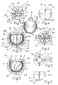
- the spherical shell 1 shown in FIGS. 1 to 5 has an upper opening 1.1 un shown in the drawing and two opposite sides Slots 2, 3. These slots 2, 3 run essentially in the direction of the central axis 4 of the spherical shell 1, which is preferred also coaxial or essentially coaxial to the central axis 5 of the associated ball joint housing 6 extends.
- the Slots 2, 3 run downwards in one towards the outside closed, in Fig. 1 by the dash-dotted Border line 1.5.1 indicated central area 1.5 of the spherical shell 1 together.
- the central area 1.5 is also as Well formed so that it can absorb lubricant can.
- the spherical shell 1 two spring deflectable shell parts 1.2 and 1.3.
- transverse slot or slots runs or run 2.2, 3.2 in the direction of the border line 1.5.1 or in the border area 1.5.2.
- the spherical shell 1 consists of resiliently elastic material, especially made of plastic. Occur as plastics all those made of or based on polyethylene, Polypropylene, polyoxymethylene, polyether sulfone, polyether ether ketone or polyamide in question.
- the inner wall 1.4 of the spherical shell 1 has grooves or channel-shaped depressions 1.6. According to FIG. 3 and 4 in the direction of the central axis 4 or according to FIG. 5 obliquely at an angle to it, arcuate, spiral or the like. run. At the opening 1.1 are depressions open there so that they can later be filled with fat can. However, you can also do all or at least there some of them will be closed. If a deepening 1.6 intersects a slot 2 or 3, the slot is 2 or 3 closed at or in front of the interface. Through the closed recess 1.6 at slot 2 or 3 can not Filling compound for forming an intermediate layer 10 in a Enter deepening 1.6.
- the recess 1.6 on the slot 2 and / or 3rd to leave open It results when snapping onto one Ball 7 of a ball pin 8 channels 9 after assembly with a lubricant, such as grease in it dispersed molybdenum disulfide. That fat can for example from the opening 1.1 or from one injected or pressed in another injection opening become.
- a lubricant such as grease in it dispersed molybdenum disulfide. That fat can for example from the opening 1.1 or from one injected or pressed in another injection opening become.
- spherical shell 1 On the outer wall 1.7 of the spherical shell 1 are on the outside protruding spacer knobs 1.8 (Fig. 1) provided that when inserted into a ball cavity 6.1 of the ball joint housing 6 on the inner wall 6.2 of the ball cavity 6.1 lightly or with little pretension or in a short distance from this. This is the location the spherical shell 1 and thus also the ball 7 in the ball cavity 6.1 specified and the spherical shell 1 fixable therein.
- Spacers 1.8.2 can also be on both sides of the Slots 2, 3 may be provided, as in FIGS. 6 and 7 can be seen.
- the spacer knobs 1.8 in the Level and / or above and / or below the equator 12 (Fig. 7) of the spherical shell 1 can be provided.
- they are arranged there at the end 2.1 or 3.1 of the slots 2 or 3.
- Those facing the sprue opening 6.3 or during injection the filling compound in the inflow surfaces 13 are aerodynamic, for example at an angle, butt to formed at an acute angle or the like.
- the central area 1.5 is located at a point where when the ball 7 is inserted, it is produced forming, deviating from the spherical shape, generally flattened Pole cap 7.1 (Fig. 3A) is present.
- the sprue opening 6.3 Injecting a filling compound or intermediate layer, as in Fig. 3 is indicated with 10.
- the intermediate layer 10 fills by the distance of the spherical shell 1 from the inner wall 6.2 of the ball cavity 6.1 formed from the cavity 11, anchored the ball socket 1 firmly in the ball joint housing 6 and compensates for all tolerances.
- the slots 2, 3 that is the base of a slot 2 or 3, one each Spacer knobs 1.8.2. This seems undesirable Tear the slots 2, 3 at the ends 2.1 and 3.1 the manufacture of the spherical shell 1 or when using it opposite.
- the slot base as a whole or it is advantageous are at least their marginal ends 2.1.1 and 3.1.1 rounded.
- the inner wall 6.2 of the Ball joint housing 6 is roughened, in particular molded Has grooves, grooves and / or grooves.
- the ball joint housing 6 is advantageously together with a Mounting flange or the like.
- the bearing shell 1 consists in particular of a non-reinforced plastic.
- the filling compound or Intermediate layer 10 can be made of glass or another consist of mineral material, possibly with Fibers, spheres or other particles can be filled.
Landscapes
- Engineering & Computer Science (AREA)
- General Engineering & Computer Science (AREA)
- Mechanical Engineering (AREA)
- Physics & Mathematics (AREA)
- Geometry (AREA)
- Pivots And Pivotal Connections (AREA)
Applications Claiming Priority (3)
| Application Number | Priority Date | Filing Date | Title |
|---|---|---|---|
| DE29722507U | 1997-12-20 | ||
| DE29722507U DE29722507U1 (de) | 1997-12-20 | 1997-12-20 | Kugelschale für ein Kugelgelenk und Kugelgelenk mit einer solchen Kugelschale |
| PCT/DE1998/003595 WO1999032796A1 (de) | 1997-12-20 | 1998-12-03 | Kugelschale für ein kugelgelenk und kugelgelenk mit einer solchen kugelschale |
Publications (2)
| Publication Number | Publication Date |
|---|---|
| EP1055076A1 EP1055076A1 (de) | 2000-11-29 |
| EP1055076B1 true EP1055076B1 (de) | 2003-07-09 |
Family
ID=8050245
Family Applications (1)
| Application Number | Title | Priority Date | Filing Date |
|---|---|---|---|
| EP98965107A Expired - Lifetime EP1055076B1 (de) | 1997-12-20 | 1998-12-03 | Kugelschale für ein kugelgelenk und kugelgelenk mit einer solchen kugelschale |
Country Status (7)
| Country | Link |
|---|---|
| EP (1) | EP1055076B1 (es) |
| JP (1) | JP2002500320A (es) |
| KR (1) | KR20010033396A (es) |
| DE (2) | DE29722507U1 (es) |
| ES (1) | ES2202929T3 (es) |
| PT (1) | PT1055076E (es) |
| WO (1) | WO1999032796A1 (es) |
Cited By (4)
| Publication number | Priority date | Publication date | Assignee | Title |
|---|---|---|---|---|
| DE10329777A1 (de) * | 2003-07-01 | 2005-02-03 | Daimlerchrysler Ag | Lagerschale für ein Kugelgelenk |
| DE102011076161A1 (de) | 2011-05-20 | 2012-11-22 | Zf Friedrichshafen Ag | Lagerschale für ein Kugelgelenk |
| US11608854B2 (en) | 2017-08-16 | 2023-03-21 | Multimatic Inc. | Ball joint with injection molded bearing |
| DE102011076160B4 (de) | 2011-05-20 | 2023-04-27 | Zf Friedrichshafen Ag | Lagerschale für ein Kugelgelenk |
Families Citing this family (19)
| Publication number | Priority date | Publication date | Assignee | Title |
|---|---|---|---|---|
| DE19832254C2 (de) * | 1998-07-17 | 2000-10-12 | Sachsenring Entwicklungsgesell | Kugelgelenk und Verfahren zu dessen Herstellung |
| DE29819498U1 (de) * | 1998-11-02 | 2000-03-16 | Sachsenring Automobiltechnik AG, 08058 Zwickau | Lagerschale und Kugelgelenk mit einer solchen Lagerschale |
| DE29819487U1 (de) * | 1998-11-02 | 2000-03-30 | Sachsenring Automobiltechnik AG, 08058 Zwickau | Kugelgelenk |
| DE19937655B4 (de) | 1999-08-13 | 2005-06-16 | ZF Lemförder Metallwaren AG | Kugelgelenk |
| DE10024554A1 (de) * | 2000-05-18 | 2001-11-29 | Zlatomir Krstin | Halterung für plattenförmige Bauteile und Baukastensystem zur Herstellung einer entsprechenden Halterung |
| DE10028984C2 (de) | 2000-06-16 | 2002-09-26 | Zf Lemfoerder Metallwaren Ag | Lagerschale für Kugelgelenke oder Kugelhülsengelenke |
| JP4514297B2 (ja) * | 2000-09-11 | 2010-07-28 | 日本発條株式会社 | ボールジョイントおよびその組立方法 |
| DE10135386A1 (de) | 2001-07-25 | 2003-02-13 | Zf Lemfoerder Metallwaren Ag | Kugelgelenk |
| DE10233489B4 (de) * | 2002-07-24 | 2004-08-12 | ZF Lemförder Metallwaren AG | Hochleistungs-Kugelschale |
| DE10346068A1 (de) * | 2003-10-04 | 2005-04-28 | Daimler Chrysler Ag | Kugelschale |
| NO323260B1 (no) * | 2004-02-12 | 2007-02-19 | Raufoss Tech As | Kuleledd for hjuloppheng og foring for kuleledd |
| DE102004022533B4 (de) | 2004-05-05 | 2006-08-03 | Zf Friedrichshafen Ag | Lagerschale |
| JP2006312948A (ja) * | 2005-05-06 | 2006-11-16 | Somic Ishikawa Inc | ボールジョイント |
| DE102006045809B4 (de) * | 2006-09-26 | 2015-06-18 | Zf Friedrichshafen Ag | Kugelgelenk |
| CN101830071A (zh) * | 2010-04-15 | 2010-09-15 | 南通杰西电器有限公司 | 一种用于微型压缩机传动机构连杆的处理工艺 |
| DE102010029137B4 (de) | 2010-05-19 | 2023-09-28 | Zf Friedrichshafen Ag | Gelenkanordnung, insbesondere Traggelenk |
| FR2970052B1 (fr) * | 2011-01-03 | 2013-12-27 | Jtekt Europe Sas | Cage pour une rotule de direction d'un vehicule |
| DE102013223042A1 (de) * | 2013-11-13 | 2015-05-13 | Schaeffler Technologies Gmbh & Co. Kg | Ausrückvorrichtung |
| WO2015070864A2 (de) * | 2013-11-13 | 2015-05-21 | Schaeffler Technologies AG & Co. KG | Betätigungseinrichtung |
Family Cites Families (11)
| Publication number | Priority date | Publication date | Assignee | Title |
|---|---|---|---|---|
| DE8420718U1 (de) * | 1984-10-04 | Robert Sihn GmbH & Co KG, 7532 Niefern-Öschelbronn | Kugelpfanne für ein Kugelgelenk | |
| DE2057513A1 (de) * | 1970-11-23 | 1972-06-15 | Elastrogran Gmbh | Kugelgelenk |
| EP0075414B1 (en) * | 1981-09-22 | 1985-11-13 | Automotive Products Public Limited Company | Ball and socket joints |
| US4619658A (en) * | 1982-02-24 | 1986-10-28 | Pappas Michael J | Spherical kinematic joint |
| JPH01131043U (es) * | 1988-03-01 | 1989-09-06 | ||
| DE3823777C1 (es) * | 1988-07-14 | 1989-11-23 | Trw Ehrenreich Gmbh & Co Kg, 4000 Duesseldorf, De | |
| DE3828683A1 (de) * | 1988-08-24 | 1990-03-08 | Lemfoerder Metallwaren Ag | Kugelgelenk fuer kraftfahrzeuge |
| US4904106A (en) * | 1989-06-26 | 1990-02-27 | Dana Corporation | Socket bearing |
| JP2605548Y2 (ja) * | 1992-02-28 | 2000-07-24 | 株式会社リズム | ボールジョイント |
| EP0659608B1 (en) * | 1993-11-30 | 1999-02-03 | Donnelly Corporation | Mirror support bracket |
| DE4421403C2 (de) * | 1994-06-18 | 1997-08-21 | Trw Fahrwerksyst Gmbh & Co | Kugelgelenk |
-
1997
- 1997-12-20 DE DE29722507U patent/DE29722507U1/de not_active Expired - Lifetime
-
1998
- 1998-12-03 EP EP98965107A patent/EP1055076B1/de not_active Expired - Lifetime
- 1998-12-03 KR KR1020007006865A patent/KR20010033396A/ko not_active Withdrawn
- 1998-12-03 JP JP2000525689A patent/JP2002500320A/ja active Pending
- 1998-12-03 DE DE59809005T patent/DE59809005D1/de not_active Expired - Lifetime
- 1998-12-03 ES ES98965107T patent/ES2202929T3/es not_active Expired - Lifetime
- 1998-12-03 WO PCT/DE1998/003595 patent/WO1999032796A1/de not_active Ceased
- 1998-12-03 PT PT98965107T patent/PT1055076E/pt unknown
Cited By (6)
| Publication number | Priority date | Publication date | Assignee | Title |
|---|---|---|---|---|
| DE10329777A1 (de) * | 2003-07-01 | 2005-02-03 | Daimlerchrysler Ag | Lagerschale für ein Kugelgelenk |
| DE10329777B4 (de) * | 2003-07-01 | 2009-08-27 | Daimler Ag | Lagerschale für ein Kugelgelenk |
| DE102011076161A1 (de) | 2011-05-20 | 2012-11-22 | Zf Friedrichshafen Ag | Lagerschale für ein Kugelgelenk |
| DE102011076160B4 (de) | 2011-05-20 | 2023-04-27 | Zf Friedrichshafen Ag | Lagerschale für ein Kugelgelenk |
| US11608854B2 (en) | 2017-08-16 | 2023-03-21 | Multimatic Inc. | Ball joint with injection molded bearing |
| US11649852B2 (en) | 2017-08-16 | 2023-05-16 | Multimatic Inc. | Ball joint with injection molded bearing |
Also Published As
| Publication number | Publication date |
|---|---|
| KR20010033396A (ko) | 2001-04-25 |
| EP1055076A1 (de) | 2000-11-29 |
| ES2202929T3 (es) | 2004-04-01 |
| WO1999032796A1 (de) | 1999-07-01 |
| DE29722507U1 (de) | 1999-04-22 |
| PT1055076E (pt) | 2003-11-28 |
| DE59809005D1 (de) | 2003-08-14 |
| JP2002500320A (ja) | 2002-01-08 |
Similar Documents
| Publication | Publication Date | Title |
|---|---|---|
| EP1055076B1 (de) | Kugelschale für ein kugelgelenk und kugelgelenk mit einer solchen kugelschale | |
| DE4305994C2 (de) | Kugelgelenk | |
| DE69735246T2 (de) | Auswechselbare Rasierklingeneinheit | |
| DE69821141T2 (de) | Steifes etui insbesondere für brillen oder ähnliches | |
| EP0929749A1 (de) | Kugelgelenk | |
| WO2014012678A1 (de) | Federfunktionsbauteil für ein hydroelastisches lager und hydroelastisches lager | |
| DE19839325C2 (de) | Fahrgastsitz mit Hohlräumen | |
| DE4115708A1 (de) | Foerdereinrichtung | |
| EP1232070B1 (de) | Befestigungsvorrichtung für eine zusatzmatte | |
| AT393003B (de) | Kaefig fuer kugellager | |
| DE19901282C1 (de) | Spritzgießwerkzeug zur Herstellung eines Wälzlagerkäfigs für ein Linearlager und Wälzlagerkäfig für ein Linearlager | |
| DE8808443U1 (de) | Kugelgelenk | |
| DE3328998A1 (de) | Wischerarmbefestigung | |
| DE3812345C2 (de) | Zwei- oder mehrteiliger Wälzlagerkäfig | |
| DE10251644B4 (de) | Hahn | |
| DE3323229A1 (de) | Kopfstuetze fuer kraftfahrzeugsitze | |
| DE2912363A1 (de) | Elektrischer schalter mit einer handhabe | |
| DE3419509A1 (de) | Buegelende eines brillenbuegels | |
| EP1421308A1 (de) | Rückschlagventil für eine pumpe | |
| DE2904290A1 (de) | Verschlussanordnung | |
| DE3521814A1 (de) | Verfahren zur herstellung eines kammkaefigs fuer ein waelzlager, spritz-, giess- oder pressform zur durchfuehrung des verfahrens und nach dem verfahren hergestellter kaefig | |
| DE4340321B4 (de) | Schnellverschlußkupplung | |
| DE2341200B2 (de) | Kugelgelenk | |
| DE3822325C1 (es) | ||
| EP0875682B1 (de) | Anschlusseinrichtung |
Legal Events
| Date | Code | Title | Description |
|---|---|---|---|
| PUAI | Public reference made under article 153(3) epc to a published international application that has entered the european phase |
Free format text: ORIGINAL CODE: 0009012 |
|
| 17P | Request for examination filed |
Effective date: 20000802 |
|
| AK | Designated contracting states |
Kind code of ref document: A1 Designated state(s): DE ES FR GB IT PT SE |
|
| 17Q | First examination report despatched |
Effective date: 20010831 |
|
| GRAG | Despatch of communication of intention to grant |
Free format text: ORIGINAL CODE: EPIDOS AGRA |
|
| GRAG | Despatch of communication of intention to grant |
Free format text: ORIGINAL CODE: EPIDOS AGRA |
|
| GRAH | Despatch of communication of intention to grant a patent |
Free format text: ORIGINAL CODE: EPIDOS IGRA |
|
| GRAH | Despatch of communication of intention to grant a patent |
Free format text: ORIGINAL CODE: EPIDOS IGRA |
|
| GRAA | (expected) grant |
Free format text: ORIGINAL CODE: 0009210 |
|
| AK | Designated contracting states |
Designated state(s): DE ES FR GB IT PT SE |
|
| REG | Reference to a national code |
Ref country code: GB Ref legal event code: FG4D Free format text: NOT ENGLISH |
|
| REF | Corresponds to: |
Ref document number: 59809005 Country of ref document: DE Date of ref document: 20030814 Kind code of ref document: P |
|
| REG | Reference to a national code |
Ref country code: SE Ref legal event code: TRGR |
|
| GBT | Gb: translation of ep patent filed (gb section 77(6)(a)/1977) |
Effective date: 20031018 |
|
| REG | Reference to a national code |
Ref country code: ES Ref legal event code: FG2A Ref document number: 2202929 Country of ref document: ES Kind code of ref document: T3 |
|
| ET | Fr: translation filed | ||
| 29U | Proceedings interrupted after grant according to rule 142 epc |
Effective date: 20020901 |
|
| REG | Reference to a national code |
Ref country code: PT Ref legal event code: PC4A Free format text: SACHSENRING ZWICKAU AG DE Effective date: 20040927 Ref country code: PT Ref legal event code: PC4A Free format text: SACHSENRING FAHRZEUGTECHNIK GMBH DE Effective date: 20040927 |
|
| REG | Reference to a national code |
Ref country code: ES Ref legal event code: PC2A |
|
| REG | Reference to a national code |
Ref country code: FR Ref legal event code: TP |
|
| PG25 | Lapsed in a contracting state [announced via postgrant information from national office to epo] |
Ref country code: IT Free format text: LAPSE BECAUSE OF NON-PAYMENT OF DUE FEES;WARNING: LAPSES OF ITALIAN PATENTS WITH EFFECTIVE DATE BEFORE 2007 MAY HAVE OCCURRED AT ANY TIME BEFORE 2007. THE CORRECT EFFECTIVE DATE MAY BE DIFFERENT FROM THE ONE RECORDED. Effective date: 20051203 |
|
| REG | Reference to a national code |
Ref country code: GB Ref legal event code: 732E |
|
| 29W | Proceedings resumed after grant [after interruption of proceedings according to rule 142 epc] |
Effective date: 20030529 |
|
| PLBE | No opposition filed within time limit |
Free format text: ORIGINAL CODE: 0009261 |
|
| STAA | Information on the status of an ep patent application or granted ep patent |
Free format text: STATUS: NO OPPOSITION FILED WITHIN TIME LIMIT |
|
| 26N | No opposition filed |
Effective date: 20040414 |
|
| PGRI | Patent reinstated in contracting state [announced from national office to epo] |
Ref country code: IT Effective date: 20110616 |
|
| REG | Reference to a national code |
Ref country code: DE Ref document number: 59809005 Country of ref document: DE Representative=s name: RUMRICH, GABRIELE, DIPL.-ING. PAT.-ING., DE Ref legal event code: R082 |
|
| REG | Reference to a national code |
Ref country code: DE Ref legal event code: R082 Ref document number: 59809005 Country of ref document: DE Representative=s name: RUMRICH, GABRIELE, DIPL.-ING. PAT.-ING., DE Effective date: 20131216 Ref country code: DE Ref legal event code: R081 Ref document number: 59809005 Country of ref document: DE Owner name: TUBE TECHNOLOGY SYSTEMS AG, DE Free format text: FORMER OWNER: HQM SACHSENRING GMBH, 08058 ZWICKAU, DE Effective date: 20150303 |
|
| REG | Reference to a national code |
Ref country code: FR Ref legal event code: PLFP Year of fee payment: 18 |
|
| REG | Reference to a national code |
Ref country code: FR Ref legal event code: PLFP Year of fee payment: 19 |
|
| REG | Reference to a national code |
Ref country code: FR Ref legal event code: PLFP Year of fee payment: 20 |
|
| PGFP | Annual fee paid to national office [announced via postgrant information from national office to epo] |
Ref country code: DE Payment date: 20171027 Year of fee payment: 20 Ref country code: FR Payment date: 20171219 Year of fee payment: 20 |
|
| PGFP | Annual fee paid to national office [announced via postgrant information from national office to epo] |
Ref country code: GB Payment date: 20171221 Year of fee payment: 20 Ref country code: SE Payment date: 20171221 Year of fee payment: 20 Ref country code: IT Payment date: 20171218 Year of fee payment: 20 Ref country code: PT Payment date: 20171127 Year of fee payment: 20 |
|
| PGFP | Annual fee paid to national office [announced via postgrant information from national office to epo] |
Ref country code: ES Payment date: 20180105 Year of fee payment: 20 |
|
| REG | Reference to a national code |
Ref country code: DE Ref legal event code: R071 Ref document number: 59809005 Country of ref document: DE |
|
| REG | Reference to a national code |
Ref country code: GB Ref legal event code: PE20 Expiry date: 20181202 |
|
| REG | Reference to a national code |
Ref country code: SE Ref legal event code: EUG |
|
| PG25 | Lapsed in a contracting state [announced via postgrant information from national office to epo] |
Ref country code: PT Free format text: LAPSE BECAUSE OF EXPIRATION OF PROTECTION Effective date: 20181211 |
|
| PG25 | Lapsed in a contracting state [announced via postgrant information from national office to epo] |
Ref country code: GB Free format text: LAPSE BECAUSE OF EXPIRATION OF PROTECTION Effective date: 20181202 |
|
| REG | Reference to a national code |
Ref country code: ES Ref legal event code: FD2A Effective date: 20200721 |
|
| PG25 | Lapsed in a contracting state [announced via postgrant information from national office to epo] |
Ref country code: ES Free format text: LAPSE BECAUSE OF EXPIRATION OF PROTECTION Effective date: 20181204 |