EP1057901A2 - Schnelllaufendes Teil für eine Maschine zur plastischen Verformung - Google Patents
Schnelllaufendes Teil für eine Maschine zur plastischen Verformung Download PDFInfo
- Publication number
- EP1057901A2 EP1057901A2 EP00111267A EP00111267A EP1057901A2 EP 1057901 A2 EP1057901 A2 EP 1057901A2 EP 00111267 A EP00111267 A EP 00111267A EP 00111267 A EP00111267 A EP 00111267A EP 1057901 A2 EP1057901 A2 EP 1057901A2
- Authority
- EP
- European Patent Office
- Prior art keywords
- fast moving
- composite
- free
- moving part
- cutting
- Prior art date
- Legal status (The legal status is an assumption and is not a legal conclusion. Google has not performed a legal analysis and makes no representation as to the accuracy of the status listed.)
- Withdrawn
Links
Images


Classifications
-
- C—CHEMISTRY; METALLURGY
- C22—METALLURGY; FERROUS OR NON-FERROUS ALLOYS; TREATMENT OF ALLOYS OR NON-FERROUS METALS
- C22C—ALLOYS
- C22C32/00—Non-ferrous alloys containing at least 5% by weight but less than 50% by weight of oxides, carbides, borides, nitrides, silicides or other metal compounds, e.g. oxynitrides, sulfides, whether added as such or formed in situ
- C22C32/001—Non-ferrous alloys containing at least 5% by weight but less than 50% by weight of oxides, carbides, borides, nitrides, silicides or other metal compounds, e.g. oxynitrides, sulfides, whether added as such or formed in situ with only oxides
- C22C32/0015—Non-ferrous alloys containing at least 5% by weight but less than 50% by weight of oxides, carbides, borides, nitrides, silicides or other metal compounds, e.g. oxynitrides, sulfides, whether added as such or formed in situ with only oxides with only single oxides as main non-metallic constituents
- C22C32/0036—Matrix based on Al, Mg, Be or alloys thereof
Definitions
- This invention relates to a fast moving part for a press, or other plastic working apparatus (or a part for a machine tool), and more particularly, to a fast moving part formed from a lightweight material of high machinability.
- aluminum-based material as herein used means aluminum, or an aluminum alloy containing a small amount of another element or elements (excluding magnesium and free-cutting inclusions), and the term “magnesium-based material” means magnesium, or a magnesium alloy containing a small amount of another element or elements (excluding aluminum and free-cutting inclusions).
- a slide for a press is basically composed of a rectangular slide case having a middle wall by which it is connected to connecting rods midway of its height, a bottom wall to which an upper die is mounted, and a plurality of reinforcing ribs having through holes extending horizontally between those two walls.
- the slide case also has four vertical guide ribs formed along its corners, respectively.
- the connecting rods are used for connecting a crankshaft and the slide.
- the slide has a hollow interior complicated in shape, and an uneven configuration around its exterior, too. Therefore, it is usually made by casting, and is often of cast iron (e.g., gray cast iron) for strength reasons.
- a frame for a press is also complicated in shape, is usually made by casting, and is of cast iron for strength reasons.
- the frictional heat produced between the slide and frame by the reciprocating motion of the slide, and the frictional heat produced by the rotational motion of the crankshaft, are transmitted to the slide by the connecting rods, and to the frame directly, and raise the temperature of the slide and frame.
- the slide and frame have a virtually equal degree of thermal expansion, since they are made of a similar, or the same, material, as stated above. Therefore, their thermal expansion does not cause any problem at all.
- a slide made of cast iron has a relatively large weight (mass), since cast iron has a high density (for example, gray cast iron has a density of 7,300 kg/m 3 ).
- the upper die mounted to the slide adds to its weight (mass), and thereby increases the force of inertia acting upon it in proportion to its mass.
- Such an increase in force of inertia is a factor hindering the realization of a high-speed and high-accuracy press.
- a high-speed press requires a crankshaft which can change its direction of rotation while it remains under a large force of inertia. If its direction of rotation is changed by resisting a large force of inertia, the crankshaft has its axis displaced, and as a consequence, the press fails to display a high accuracy.
- a slide made of a light alloy is, however, likely to be scored or worn easily by a cast iron frame along which it is slidable, when its temperature has been raised by the frictional heat resulting from its motion at a high speed, since there is a large difference in coefficient of thermal expansion between a light alloy and cast iron.
- an aluminum alloy has a thermal expansion coefficient of 21.1 ⁇ 10 -6 /m° C, while that of gray cast iron is 9.8 ⁇ 10 -6 /m° C.
- a slide of a light alloy is generally less strong than one of cast iron because of its lower rigidity. It is, therefore, likely that an upper die mounted to the bottom of the slide may cause it to sag and may be displaced from its right position in a press. If such is the case, it is difficult to realize any press working of high accuracy.
- Japanese Patent Laid-Open No. 193196/1998 proposes a slide for a press which is formed from a composite having an aluminum-based matrix and containing a ceramic material.
- the slide as proposed is light in weight, and can overcome the problems of thermal expansion and strength as pointed out above.
- the composite contains silicon carbide (SiC) or alumina (Al 2 O 3 ) in its aluminum matrix, and these materials are by far harder than metals, and damage a cutting tool, and lower the machinability of the composite.
- This object is essentially attained by a part of which the whole, or a principal portion, is formed from a composite containing a ceramic material in a light metal matrix, and having a specific gravity not exceeding 3.2, a Brinell hardness of 130 to 400, and a coefficient of linear expansion not exceeding 16.0 ⁇ 10 -6 /° C, the composite further containing 0.1 to 1.0% by weight of free-cutting inclusions.
- the light metal matrix may be of an aluminum-based material, and the composite may contain the ceramic material in the amount of 10% to 45%, preferably 15% to 35%, by volume, and the free-cutting inclusions in the amount of 0.20% to 0.35%, preferably 0.22% to 0.32%, by weight.
- the light metal matrix may alternatively be of an aluminum-based material and a magnesium-based material mixed in a ratio by volume of 9/1 to 1/9, and the composite may contain ceramic material in the amount of 5% to 45% by volume, and free-cutting inclusions in the amount of 0.02% to 0.60% by weight.
- the light metal matrix may also be of a magnesium-based material, and the composite may contain ceramic material in the amount of 10% to 45% by volume, and free-cutting inclusions in the amount of 0.20% to 0.70% by weight.
- the part, or its principal portion, is usually made by casting. It preferably forms a slide for a press.
- the slide preferably comprises a main body formed by the principal portion of the part according to this invention and an adaptor attached detachably to the main body.
- a fast moving part, or slide 10, embodying this invention is shown in Fig. 1, and is incorporated in a straight-sided press 1 as shown in Fig. 2.
- the slide 10 is connected to a crankshaft installed in a crown 2, but not shown, by connecting rods 5, and is mounted in a column (or frame) 3.
- the slide 10 carries at its bottom an upper die 6, which is reciprocatable to and away from a lower die 9 supported by a bolster 7 on a bed 4.
- the slide 10 has four guide ribs 15, which are guided by the column 3 for moving the slide 10, while maintaining it in parallel to the lower die 9.
- the slide comprises a main body 10 and an adaptor plate 13, attached detachably to a bottom of the main body 10 by bolts, or the like. Therefore, only the main body 10 (the fast moving parts main portion) is formed from a light metal composite containing free-cutting inclusions, since its complicated shape requires a cutting job of high accuracy, while the adaptor plate 13 can be formed from a light metal composite not containing any tree-cutting inclusions, since its shape requires only little, or substantially no cutting work. This enables a corresponding reduction in the use of the composite containing free-cutting inclusions, which is expensive. Moreover, the whole slide does not have to be changed, but only the adaptor plate 13 has to be changed, when the dies have to be changed. Other parts, such as the guide ribs 15, can also be prepared as detachable members if they require only little, or no, cutting work.
- the main body 10 is shaped like a rectangular case, and the guide ribs 15 extend along the four corners thereof, respectively, and project downwards below the adaptor plate 13. It has a rod-connecting wall 11 which lies midway of the height of the case, and to which the connecting rods 5 are connected. It has an open space above its rod-connecting wall 11, and the rod-connecting wall 11 and the adaptor plate 13 define therebetween a hollow space surrounded by a wall having a plurality of holes 10a through which core sand can be removed.
- Fig. 3 shows a different form of slide 19 embodying this invention which is mainly used in a C type press.
- the slide 19 includes a pair of parallel guide posts 21 extending vertically along two opposite edges, respectively, of its back, and each having a sloping surface, and a pair of ribs 27 projecting forwards from the guide posts 21, respectively, in parallel with each other. It also has a bearing 23 formed between the lower portions of the ribs 27 for supporting a connecting rod, and located above an adaptor plate 25 to which an upper die can be mounted.
- the slide (fast moving part) 10 or 19 is designed for making a vertical reciprocating motion at a high speed to enable the upper die to apply pressure to the workpiece. Therefore, it is required to be wear resistant, rigid and hard enough to resist wear and deformation.
- the slide is also required to be light in weight, low in coefficient of thermal expansion, and easy to make by cutting.
- the link and lever mechanism is a mechanism for changing a rotary motion into a rectilinear motion for driving a slide in a link press.
- the mechanism is required to be strong enough to resist any high-speed rotary motion and impact when the slide makes a reciprocating rectilinear motion at a high speed for applying pressure to the material to be pressed. Therefore, its connecting ends are desired to have a high wear resistance, a high rigidity, a light weight and a low coefficient of thermal expansion.
- the connecting rod connects a crankshaft and a slide in a crank press, and is driven by the crankshaft for driving the slide. It is required to be wear resistant, particularly at its connecting ends, when the slide makes a reciprocating motion at a high speed for applying pressure to the material to be pressed. It is also desired that the connecting rod be highly rigid to resist any impact, as well as having a light weight.
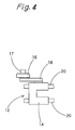
- This invention is also applicable to a fast moving part in a transporting device used with, or incorporated in a press, or other plastic working apparatus, for example, a gripper feeder 12 as shown in Fig. 4, or a transfer 22 as shown in Fig. 5.
- the gripper feeder 12 is used for conveying the workpiece (or material to be pressed) to a working position in a timely way for its press working. It includes a movable gripper 14 capable of a reciprocating motion at a high speed as a fast moving part embodying this invention.
- the gripper 14 is required to be wear resistant and light in weight.
- the crank lever is required to have a high wear resistance and a high rigidity.
- the transfer 22 is a device for conveying the workpiece in straight lines to enable multiple steps of processing to be performed in parallel with each other.
- the transfer 22 includes a pair of feed bars 24 for making a rectangular motion at a high speed to feed the material for its continuous multi-stage working. This pair of feed bars 24 are, therefore, required to be light in weight, rigid and wear resistant.
- the device also includes a framework 26 and a cam case 28.
- every fast moving part such as the slide 10 or 19, movable gripper 14, or each feed bar 24, be formed from a composite containing a light metal matrix. It is, however, not necessary to form the whole part from such a material, but it is sufficient to form at least its principal portion from such a material.
- the composite further contains a ceramic material.
- the ceramic material which it may include is, for example, an oxide such as Al 2 O 3 , TiO 2 , ZrO 2 , MgO or SiO 2 , a carbide such as SiC, B 4 C, ZrC, WC, TiC or NbC, a boride such as TiB 2 or MoB 2 , a nitride such as AlN or BN, or a partly stabilized zirconia obtained by adding a silicide, CaO or Y 2 O 3 , to zirconium.
- Alumina (Al 2 O 3 ) or silicon carbide (Sic) is, among others, preferred, since each of these facilitates the preparation of an appropriately hard (and strong) composite having a low coefficient of linear expansion, while being a common material.
- the ceramic material to be selected depends on the light metal used as the matrix, and the hardness and coefficient of linear expansion as required of the composite.
- the amount of the ceramic material to be incorporated depends on the hardness and coefficient of linear expansion as required of the composite.
- the high heat resistance of the ceramic material and its low coefficient of thermal expansion ensure the accuracy of working by an apparatus including a fast moving part according to this invention. Its high wear resistance protects the part from being easily worn as a result of its repeated motion at a high speed. Its high bending strength and rigidity minimize the possibility of deformation of the part. Its high hardness imparts an adequate hardness to the part if the composite has an adequate ceramic content.
- composition of the composite giving it the mechanical properties as will be stated below depends on the light metal employed as its matrix, it may usually have a ceramic content of at least 5%, preferably at least 10%, or more preferably at least 20%, by volume. Its maximum is limited to a level not affecting the machinability of the composite containing free-cutting inclusions, if any, and may usually be less than 50%, preferably not more than 45%, or more preferably not more than 35%, by volume.
- the light metal means both a light metal and a light alloy, and more specifically, it is a material based on at least one metal selected from the group consisting of aluminum (Al), magnesium (Mg), titanium (Ti) and beryllium (Be).
- the alloy may contain a small amount of another metal, or nonmetal element or elements, too.
- An aluminum- or magnesium-based material, or both, are usually employed, as they are relatively easily available.
- the aluminum- and magnesium-based materials are as defined before.
- the selection of the aluminum- or magnesium-based material depends on the properties as desired of the composite, particularly its desired specific gravity. Therefore, a composition containing at least a specific amount of magnesium-based material is selected if a light weight is strongly desired.
- Aluminum has a broad range of use as an industrial material, and is suitable for a fast moving part of light weight because of its specific gravity (or density) of 2.7, which is as low as about one-third of that of gray cast iron, while it also has a high affinity for a ceramic material and is of high uniformity in quality. It is also high in corrosion resistance, machinability and castability.
- Magnesium can make a fast moving part of still lighter weight, as it has a specific gravity of 1.74, which is lower than that of aluminum (2.7), and of any other metal in practical use. It also has a high affinity for a ceramic material and is easy to work (cut).
- Both aluminum and magnesium are usually employed in the form of their respective alloys, such as an aluminum alloy containing copper, nickel, manganese, silicon, zinc or chromium, and a magnesium alloy containing zinc, zirconium, a rare earth element or silver, since the alloys exhibit still better mechanical properties.
- specific examples of those light alloys are:
- Casting is a suitable method for making a fast moving machine part having a complicated shape as described above.
- a composite containing a light metal matrix which was very difficult to prepare, has become easier to prepare by, for example, casting, or pressureless cementation. It is worthy of particular mention that a composite containing 20% or more of a ceramic material in a light metal matrix has recently become available for a wide range of uses as a lightweight and highly rigid material, and is applicable to a fast moving machine part having a complicated shape.
- a special casting method such as die casting or thixotropic molding, has been drawing attention as a desirable method.
- An oxide type ceramic material and aluminum often contain a considerable amount of oxygen, and require special care for adequate deoxidation prior to casting and degassing during casting. Stirring for the uniform dispersion of ceramic particles and bubbling by an inert gas are necessary before a fast moving machine part is made by casting.
- the known composite containing a light metal matrix is very low in machinability because of its high ceramic content which is necessary for giving it mechanical properties, particularly a coefficient of linear expansion, close to those of steel, as stated before. Therefore, the composite for making a fast moving machine part according to this invention further contains 0.1% to 1.0% by weight of free-cutting inclusions which improve its machinability.
- the improved machinability of the composite is essential, since a fast moving machine part is manufactured from an ingot, or a cast product, by machining, including cutting, such as lathing, drilling, boring, milling, planing, slotting or broaching, and grinding.
- the machinability is determined by considering (1) the wear resistance of a tool, (2) the disposability of chips, (3) the smoothness of a finished surface, and (4) the cutting resistance acting upon the tool.
- the improvement of (1) the wear resistance of the tool, and (3) the smoothness of a finished surface is, among others, of importance.
- any known free-cutting inclusions used for making free-cutting steel, free-cutting stainless steel, a free-cutting aluminum alloy, etc. can, however, be used for the purpose of this invention.
- a mixture of two or more substances is usually employed.
- the composite may contain, for example, metallic inclusions such as particles of lead (Pb), bismuth (Bi) or tellurium (Te), or nonmetallic inclusions in the form of an oxide such as anorthite CaO ⁇ Al 2 O 3 or gehlenite 2CaO ⁇ Al 2 O 3 ⁇ SiO 2 , or in the form of a compound of an element of the sulfur group, such as MnS, MnSe or MnTe.
- metallic inclusions such as particles of lead (Pb), bismuth (Bi) or tellurium (Te)
- nonmetallic inclusions in the form of an oxide such as anorthite CaO ⁇ Al 2 O 3 or gehlenite 2CaO ⁇ Al 2 O 3 ⁇
- the proportion of the free-cutting inclusions in the composite depends on the material used as the matrix, the ceramic material used and its proportion, but is usually from 0.1% to 1.0% by weight. If their proportion exceeds 1.0% by weight, these inclusions are likely to exert an adverse effect on the mechanical properties of the composite, and if they are lower than 0. 1% by weight, These inclusions cannot be expected to improve the free-cutting property of the composite.
- the composite may usually be of any of the following compositions:
- the free-cutting inclusions are usually added when the alloying elements are added.
- the fast moving part of this invention for a plastic working apparatus enables it to operate at a higher speed with a higher accuracy, since it has such a light weight owing to the light metal matrix that its fast motion does not produce any undesirably large force of inertia.
- the ceramic material which it contains also contributes to a higher speed and accuracy of operation, since the composite containing a ceramic material has a lower coefficient of thermal expansion and higher mechanical properties including wear resistance, strength and rigidity properties, than those of any known aluminum alloy.
- the composite containing a small amount of free-cutting inclusions is easier to work on for making any machine part having a complicated shape than any known composite, and thereby enables any cutting tool to have a prolonged life.
- the fast moving part of this invention which can be made by casting requires only a smaller amount of later cutting work, and thereby makes it possible to increase the productivity of the apparatus and process employed for making it, even though it may have a complicated shape.
- the fast moving part of this invention may have a main body formed separately from its remaining portion, and used as a standardized part for a variety of types of dies, so that it may be possible to increase the productivity of the apparatus and process employed for making any such part.
- the aluminum- and magnesium-based materials were each of the following composition, while silicon carbide (SiC) was used as the ceramic material, and manganese sulfide as free-cutting inclusions:
- Aluminum-based material The Al-Mg alloy containing 0.1% Cu, 0.35% Si, 10% Mg, 0.1% Zn, 0.35% Fe, 0.1% Mn and 0.2% Ti in addition to aluminum; and
- Magnesium-based material The Mg-Al-Zn-Mn alloy containing 5.3% to 6.7% Al, 2.5% to 3.5% Zn, 0.15% to 0.6% Mn, not more than 0.3% Si, 0.25% Cu and not more than 0.01% Ni in addition to magnesium.
- a diamond tool was used for making a cut depth of 0.05 mm by employing a cutting speed of 50 m/min., a feed rate of 0.01 mm/rev., and a water-soluble cutting oil.
- the results of the cutting tests and the overall evaluation of each material were classified into 'Very good', 'Good', 'Somewhat poor' and 'Very poor, which are shown by a double circle, a circle, a triangle and an x, respectively, in Table 2.
- the composite according to Example 1 contains about 20% by volume of ceramic material, about 80% by volume of aluminum-based material, and 0.25% by weight of free-cutting inclusions. It has a density of 3,100 kg/m 3 and is, therefore, substantially as light in weight as any known aluminum alloy. Its linear expansion coefficient of 15.1 ⁇ 10 -6 /m° C is considerably lower than that of any aluminum alloy, and althugh its linear expansion coeffcient is about 1.6 times higher than that of gray cast iron, it falls within the acceptable range. Its tensile strength of 355 MPa is higher than that of any aluminum alloy, or gray cast iron, and it is satisfactory in elongation, too.
- Example 1 Al-based material Mg-based material Ceramic Free-cutting inclusions (vol%) (vol%) (wt%) Control Example 1 100 0 0 0.10 Example 1 80 0 20 0.25 Example 2 70 0 30 0.30 Example 3 60 0 40 0.33 Control Example 2 50 0 50 0.22 Example 4 80 10 10 0.15 Example 5 40 20 40 0.55 Example 6 40 30 30 0.05 Example 7 40 40 20 0.05 Control Example 3 40 40 20 0 Example 8 0 60 40 0.55 Example 9 0 80 20 0.55 Reference Example Cast iron (FC250)
Landscapes
- Chemical & Material Sciences (AREA)
- Engineering & Computer Science (AREA)
- Materials Engineering (AREA)
- Mechanical Engineering (AREA)
- Metallurgy (AREA)
- Organic Chemistry (AREA)
- Manufacture Of Alloys Or Alloy Compounds (AREA)
- Presses And Accessory Devices Thereof (AREA)
- Braking Arrangements (AREA)
- Forging (AREA)
Applications Claiming Priority (4)
| Application Number | Priority Date | Filing Date | Title |
|---|---|---|---|
| JP15598999 | 1999-06-03 | ||
| JP15598999 | 1999-06-03 | ||
| JP2000108499A JP2001047298A (ja) | 1999-06-03 | 2000-04-10 | 塑性加工装置の高速運動部品 |
| JP2000108499 | 2000-04-10 |
Publications (2)
| Publication Number | Publication Date |
|---|---|
| EP1057901A2 true EP1057901A2 (de) | 2000-12-06 |
| EP1057901A3 EP1057901A3 (de) | 2002-02-06 |
Family
ID=26483843
Family Applications (1)
| Application Number | Title | Priority Date | Filing Date |
|---|---|---|---|
| EP00111267A Withdrawn EP1057901A3 (de) | 1999-06-03 | 2000-05-25 | Schnelllaufendes Teil für eine Maschine zur plastischen Verformung |
Country Status (3)
| Country | Link |
|---|---|
| US (1) | US20010002240A1 (de) |
| EP (1) | EP1057901A3 (de) |
| JP (1) | JP2001047298A (de) |
Cited By (2)
| Publication number | Priority date | Publication date | Assignee | Title |
|---|---|---|---|---|
| EP1477576A4 (de) * | 2002-02-15 | 2005-07-13 | Toudai Tlo Ltd | Verbundwerkstoff auf magnesiumbasis und herstellungsverfahren dafür |
| CN103898384A (zh) * | 2014-04-23 | 2014-07-02 | 大连海事大学 | 可溶性镁基合金材料,其制备方法及应用 |
Families Citing this family (9)
| Publication number | Priority date | Publication date | Assignee | Title |
|---|---|---|---|---|
| JP2002307200A (ja) * | 2001-04-13 | 2002-10-22 | Yamada Dobby Co Ltd | 塑性加工装置の高速運動部品 |
| JP2004048919A (ja) * | 2002-07-12 | 2004-02-12 | Nikon Corp | リニアモータ及びステージ装置並びに露光装置 |
| CN101332561B (zh) * | 2007-06-25 | 2012-11-21 | 鸿富锦精密工业(深圳)有限公司 | 机床 |
| CN101332574B (zh) * | 2007-06-28 | 2012-11-21 | 鸿富锦精密工业(深圳)有限公司 | 机床 |
| CN101332570A (zh) * | 2007-06-28 | 2008-12-31 | 鸿富锦精密工业(深圳)有限公司 | 机床 |
| CN101332575B (zh) * | 2007-06-28 | 2013-01-09 | 鸿富锦精密工业(深圳)有限公司 | 机床 |
| CN104789842B (zh) * | 2015-04-01 | 2016-08-24 | 河南科技大学 | 一种耐高温高强度镁合金的制备方法 |
| ES2935171T3 (es) * | 2017-12-28 | 2023-03-02 | Fehrmann Alloys Gmbh & Co Kg | Aleación de aluminio |
| JP7195327B2 (ja) * | 2017-12-28 | 2022-12-23 | フェールマン ゲーエムベーハー | アルミニウム合金 |
Family Cites Families (3)
| Publication number | Priority date | Publication date | Assignee | Title |
|---|---|---|---|---|
| JPH072980B2 (ja) * | 1990-09-20 | 1995-01-18 | 大同メタル工業株式会社 | 複合摺動材料 |
| AUPN273695A0 (en) * | 1995-05-02 | 1995-05-25 | University Of Queensland, The | Aluminium alloy powder blends and sintered aluminium alloys |
| JPH10193196A (ja) * | 1997-01-09 | 1998-07-28 | Yamada Dobby Co Ltd | プレス機のスライド |
-
2000
- 2000-04-10 JP JP2000108499A patent/JP2001047298A/ja active Pending
- 2000-05-25 EP EP00111267A patent/EP1057901A3/de not_active Withdrawn
-
2001
- 2001-01-05 US US09/754,380 patent/US20010002240A1/en not_active Abandoned
Cited By (4)
| Publication number | Priority date | Publication date | Assignee | Title |
|---|---|---|---|---|
| EP1477576A4 (de) * | 2002-02-15 | 2005-07-13 | Toudai Tlo Ltd | Verbundwerkstoff auf magnesiumbasis und herstellungsverfahren dafür |
| US7052526B2 (en) | 2002-02-15 | 2006-05-30 | Toudai Tlo, Ltd. | Magnesium base composite material and its manufacturing method |
| CN103898384A (zh) * | 2014-04-23 | 2014-07-02 | 大连海事大学 | 可溶性镁基合金材料,其制备方法及应用 |
| CN103898384B (zh) * | 2014-04-23 | 2016-04-20 | 大连海事大学 | 可溶性镁基合金材料,其制备方法及应用 |
Also Published As
| Publication number | Publication date |
|---|---|
| JP2001047298A (ja) | 2001-02-20 |
| EP1057901A3 (de) | 2002-02-06 |
| US20010002240A1 (en) | 2001-05-31 |
Similar Documents
| Publication | Publication Date | Title |
|---|---|---|
| EP1057901A2 (de) | Schnelllaufendes Teil für eine Maschine zur plastischen Verformung | |
| US5225007A (en) | Method for wear-resistant compound roll manufacture | |
| US6416598B1 (en) | Free machining aluminum alloy with high melting point machining constituent and method of use | |
| JP2779164B2 (ja) | 工具鋼 | |
| EP3050638B1 (de) | Zentrifugal gegossene verbundstoffwalze und verfahren zur herstellung davon | |
| US20080008616A1 (en) | Fabrication of hardmetals having binders with rhenium or ni-based superalloy | |
| EP0672760A1 (de) | Verschliessfeste Gusslegierung aus Aluminium und Verfahren zur Herstellung | |
| EP0704543B1 (de) | Gleitstück aus gesinterter aluminiumlegierung | |
| DK162881B (da) | Fremgangsmaade til fremstilling af et sejt, slidbestandigt formlegeme | |
| WO2002077309A1 (fr) | Acier moule et moule metallique destine a la coulee | |
| JP2636816B2 (ja) | 合金工具鋼 | |
| US6066291A (en) | Nickel aluminide intermetallic alloys for tooling applications | |
| CN101412093A (zh) | 一种复合耐磨锤头的制备方法 | |
| JP4213022B2 (ja) | 溶製法で製造可能な高剛性鋼及びその製造方法 | |
| JPH1068048A (ja) | 高剛性高靱性鋼およびその製造方法 | |
| JP2507765B2 (ja) | 高速度工具鋼 | |
| US20050158204A1 (en) | Method of production of broadside plates for continuous casting molds | |
| US6033498A (en) | Thermal processing of nickel aluminide alloys to improve mechanical properties | |
| CN109136714A (zh) | 一种用于锂电池分切机的硬质合金材料 | |
| JPH01215947A (ja) | 切削又は切断工具部材用超硬合金 | |
| JPH06299298A (ja) | 高速度工具鋼 | |
| JP2716441B2 (ja) | 高速度工具鋼 | |
| JPH04198442A (ja) | 高靭性亜鉛基合金 | |
| US2327561A (en) | Silver-containing free-machining die steel | |
| Chumanov et al. | Investigation of macro-and microstructure of experimental composite materials obtained by disperse hardening method |
Legal Events
| Date | Code | Title | Description |
|---|---|---|---|
| PUAI | Public reference made under article 153(3) epc to a published international application that has entered the european phase |
Free format text: ORIGINAL CODE: 0009012 |
|
| AK | Designated contracting states |
Kind code of ref document: A2 Designated state(s): CH DE LI Kind code of ref document: A2 Designated state(s): AT BE CH CY DE DK ES FI FR GB GR IE IT LI LU MC NL PT SE |
|
| AX | Request for extension of the european patent |
Free format text: AL;LT;LV;MK;RO;SI |
|
| PUAL | Search report despatched |
Free format text: ORIGINAL CODE: 0009013 |
|
| RIC1 | Information provided on ipc code assigned before grant |
Free format text: 7C 22C 32/00 A, 7B 30B 15/06 B, 7B 29C 43/32 B, 7C 22C 21/00 B |
|
| AK | Designated contracting states |
Kind code of ref document: A3 Designated state(s): AT BE CH CY DE DK ES FI FR GB GR IE IT LI LU MC NL PT SE |
|
| AX | Request for extension of the european patent |
Free format text: AL;LT;LV;MK;RO;SI |
|
| 17P | Request for examination filed |
Effective date: 20020308 |
|
| AKX | Designation fees paid |
Free format text: CH DE LI |
|
| 17Q | First examination report despatched |
Effective date: 20031006 |
|
| STAA | Information on the status of an ep patent application or granted ep patent |
Free format text: STATUS: THE APPLICATION IS DEEMED TO BE WITHDRAWN |
|
| 18D | Application deemed to be withdrawn |
Effective date: 20031202 |