EP1058019B1 - Commande pour un embrayage actionné par fluide - Google Patents
Commande pour un embrayage actionné par fluide Download PDFInfo
- Publication number
- EP1058019B1 EP1058019B1 EP99110762A EP99110762A EP1058019B1 EP 1058019 B1 EP1058019 B1 EP 1058019B1 EP 99110762 A EP99110762 A EP 99110762A EP 99110762 A EP99110762 A EP 99110762A EP 1058019 B1 EP1058019 B1 EP 1058019B1
- Authority
- EP
- European Patent Office
- Prior art keywords
- clutch
- slip
- control
- pressure
- forward model
- Prior art date
- Legal status (The legal status is an assumption and is not a legal conclusion. Google has not performed a legal analysis and makes no representation as to the accuracy of the status listed.)
- Expired - Lifetime
Links
- 239000012530 fluid Substances 0.000 title description 3
- 230000005540 biological transmission Effects 0.000 claims description 18
- 238000000034 method Methods 0.000 claims description 15
- 230000008859 change Effects 0.000 claims description 5
- 230000009123 feedback regulation Effects 0.000 claims 1
- 238000010168 coupling process Methods 0.000 description 9
- 230000008878 coupling Effects 0.000 description 8
- 238000005859 coupling reaction Methods 0.000 description 8
- 230000007704 transition Effects 0.000 description 8
- 230000001419 dependent effect Effects 0.000 description 4
- 238000010586 diagram Methods 0.000 description 3
- 230000006870 function Effects 0.000 description 3
- 239000010720 hydraulic oil Substances 0.000 description 3
- 230000001105 regulatory effect Effects 0.000 description 3
- 230000008569 process Effects 0.000 description 2
- 230000004044 response Effects 0.000 description 2
- 230000032683 aging Effects 0.000 description 1
- 230000015572 biosynthetic process Effects 0.000 description 1
- 238000010276 construction Methods 0.000 description 1
- 230000018109 developmental process Effects 0.000 description 1
- 230000000694 effects Effects 0.000 description 1
- 239000000446 fuel Substances 0.000 description 1
- 230000006872 improvement Effects 0.000 description 1
- 230000008447 perception Effects 0.000 description 1
- 230000002265 prevention Effects 0.000 description 1
- 238000005096 rolling process Methods 0.000 description 1
- 230000003068 static effect Effects 0.000 description 1
- 238000009423 ventilation Methods 0.000 description 1
Images


Classifications
-
- F—MECHANICAL ENGINEERING; LIGHTING; HEATING; WEAPONS; BLASTING
- F16—ENGINEERING ELEMENTS AND UNITS; GENERAL MEASURES FOR PRODUCING AND MAINTAINING EFFECTIVE FUNCTIONING OF MACHINES OR INSTALLATIONS; THERMAL INSULATION IN GENERAL
- F16D—COUPLINGS FOR TRANSMITTING ROTATION; CLUTCHES; BRAKES
- F16D48/00—External control of clutches
- F16D48/06—Control by electric or electronic means, e.g. of fluid pressure
- F16D48/066—Control of fluid pressure, e.g. using an accumulator
-
- B—PERFORMING OPERATIONS; TRANSPORTING
- B60—VEHICLES IN GENERAL
- B60W—CONJOINT CONTROL OF VEHICLE SUB-UNITS OF DIFFERENT TYPE OR DIFFERENT FUNCTION; CONTROL SYSTEMS SPECIALLY ADAPTED FOR HYBRID VEHICLES; ROAD VEHICLE DRIVE CONTROL SYSTEMS FOR PURPOSES NOT RELATED TO THE CONTROL OF A PARTICULAR SUB-UNIT
- B60W50/00—Details of control systems for road vehicle drive control not related to the control of a particular sub-unit, e.g. process diagnostic or vehicle driver interfaces
- B60W2050/0001—Details of the control system
- B60W2050/0002—Automatic control, details of type of controller or control system architecture
- B60W2050/0012—Feedforward or open loop systems
-
- B—PERFORMING OPERATIONS; TRANSPORTING
- B60—VEHICLES IN GENERAL
- B60W—CONJOINT CONTROL OF VEHICLE SUB-UNITS OF DIFFERENT TYPE OR DIFFERENT FUNCTION; CONTROL SYSTEMS SPECIALLY ADAPTED FOR HYBRID VEHICLES; ROAD VEHICLE DRIVE CONTROL SYSTEMS FOR PURPOSES NOT RELATED TO THE CONTROL OF A PARTICULAR SUB-UNIT
- B60W50/00—Details of control systems for road vehicle drive control not related to the control of a particular sub-unit, e.g. process diagnostic or vehicle driver interfaces
- B60W2050/0001—Details of the control system
- B60W2050/0019—Control system elements or transfer functions
- B60W2050/0028—Mathematical models, e.g. for simulation
- B60W2050/0031—Mathematical model of the vehicle
-
- B—PERFORMING OPERATIONS; TRANSPORTING
- B60—VEHICLES IN GENERAL
- B60W—CONJOINT CONTROL OF VEHICLE SUB-UNITS OF DIFFERENT TYPE OR DIFFERENT FUNCTION; CONTROL SYSTEMS SPECIALLY ADAPTED FOR HYBRID VEHICLES; ROAD VEHICLE DRIVE CONTROL SYSTEMS FOR PURPOSES NOT RELATED TO THE CONTROL OF A PARTICULAR SUB-UNIT
- B60W2510/00—Input parameters relating to a particular sub-units
- B60W2510/02—Clutches
- B60W2510/0241—Clutch slip, i.e. difference between input and output speeds
-
- B—PERFORMING OPERATIONS; TRANSPORTING
- B60—VEHICLES IN GENERAL
- B60W—CONJOINT CONTROL OF VEHICLE SUB-UNITS OF DIFFERENT TYPE OR DIFFERENT FUNCTION; CONTROL SYSTEMS SPECIALLY ADAPTED FOR HYBRID VEHICLES; ROAD VEHICLE DRIVE CONTROL SYSTEMS FOR PURPOSES NOT RELATED TO THE CONTROL OF A PARTICULAR SUB-UNIT
- B60W2510/00—Input parameters relating to a particular sub-units
- B60W2510/06—Combustion engines, Gas turbines
- B60W2510/0604—Throttle position
-
- B—PERFORMING OPERATIONS; TRANSPORTING
- B60—VEHICLES IN GENERAL
- B60W—CONJOINT CONTROL OF VEHICLE SUB-UNITS OF DIFFERENT TYPE OR DIFFERENT FUNCTION; CONTROL SYSTEMS SPECIALLY ADAPTED FOR HYBRID VEHICLES; ROAD VEHICLE DRIVE CONTROL SYSTEMS FOR PURPOSES NOT RELATED TO THE CONTROL OF A PARTICULAR SUB-UNIT
- B60W2540/00—Input parameters relating to occupants
- B60W2540/10—Accelerator pedal position
- B60W2540/106—Rate of change
-
- B—PERFORMING OPERATIONS; TRANSPORTING
- B60—VEHICLES IN GENERAL
- B60W—CONJOINT CONTROL OF VEHICLE SUB-UNITS OF DIFFERENT TYPE OR DIFFERENT FUNCTION; CONTROL SYSTEMS SPECIALLY ADAPTED FOR HYBRID VEHICLES; ROAD VEHICLE DRIVE CONTROL SYSTEMS FOR PURPOSES NOT RELATED TO THE CONTROL OF A PARTICULAR SUB-UNIT
- B60W2710/00—Output or target parameters relating to a particular sub-units
- B60W2710/02—Clutches
- B60W2710/025—Clutch slip, i.e. difference between input and output speeds
-
- B—PERFORMING OPERATIONS; TRANSPORTING
- B60—VEHICLES IN GENERAL
- B60W—CONJOINT CONTROL OF VEHICLE SUB-UNITS OF DIFFERENT TYPE OR DIFFERENT FUNCTION; CONTROL SYSTEMS SPECIALLY ADAPTED FOR HYBRID VEHICLES; ROAD VEHICLE DRIVE CONTROL SYSTEMS FOR PURPOSES NOT RELATED TO THE CONTROL OF A PARTICULAR SUB-UNIT
- B60W2710/00—Output or target parameters relating to a particular sub-units
- B60W2710/02—Clutches
- B60W2710/027—Clutch torque
-
- B—PERFORMING OPERATIONS; TRANSPORTING
- B60—VEHICLES IN GENERAL
- B60W—CONJOINT CONTROL OF VEHICLE SUB-UNITS OF DIFFERENT TYPE OR DIFFERENT FUNCTION; CONTROL SYSTEMS SPECIALLY ADAPTED FOR HYBRID VEHICLES; ROAD VEHICLE DRIVE CONTROL SYSTEMS FOR PURPOSES NOT RELATED TO THE CONTROL OF A PARTICULAR SUB-UNIT
- B60W30/00—Purposes of road vehicle drive control systems not related to the control of a particular sub-unit, e.g. of systems using conjoint control of vehicle sub-units
- B60W30/18—Propelling the vehicle
- B60W30/20—Reducing vibrations in the driveline
-
- F—MECHANICAL ENGINEERING; LIGHTING; HEATING; WEAPONS; BLASTING
- F16—ENGINEERING ELEMENTS AND UNITS; GENERAL MEASURES FOR PRODUCING AND MAINTAINING EFFECTIVE FUNCTIONING OF MACHINES OR INSTALLATIONS; THERMAL INSULATION IN GENERAL
- F16D—COUPLINGS FOR TRANSMITTING ROTATION; CLUTCHES; BRAKES
- F16D2500/00—External control of clutches by electric or electronic means
- F16D2500/30—Signal inputs
- F16D2500/304—Signal inputs from the clutch
- F16D2500/30404—Clutch temperature
-
- F—MECHANICAL ENGINEERING; LIGHTING; HEATING; WEAPONS; BLASTING
- F16—ENGINEERING ELEMENTS AND UNITS; GENERAL MEASURES FOR PRODUCING AND MAINTAINING EFFECTIVE FUNCTIONING OF MACHINES OR INSTALLATIONS; THERMAL INSULATION IN GENERAL
- F16D—COUPLINGS FOR TRANSMITTING ROTATION; CLUTCHES; BRAKES
- F16D2500/00—External control of clutches by electric or electronic means
- F16D2500/30—Signal inputs
- F16D2500/306—Signal inputs from the engine
- F16D2500/3067—Speed of the engine
-
- F—MECHANICAL ENGINEERING; LIGHTING; HEATING; WEAPONS; BLASTING
- F16—ENGINEERING ELEMENTS AND UNITS; GENERAL MEASURES FOR PRODUCING AND MAINTAINING EFFECTIVE FUNCTIONING OF MACHINES OR INSTALLATIONS; THERMAL INSULATION IN GENERAL
- F16D—COUPLINGS FOR TRANSMITTING ROTATION; CLUTCHES; BRAKES
- F16D2500/00—External control of clutches by electric or electronic means
- F16D2500/30—Signal inputs
- F16D2500/308—Signal inputs from the transmission
- F16D2500/3081—Signal inputs from the transmission from the input shaft
- F16D2500/30816—Speed of the input shaft
-
- F—MECHANICAL ENGINEERING; LIGHTING; HEATING; WEAPONS; BLASTING
- F16—ENGINEERING ELEMENTS AND UNITS; GENERAL MEASURES FOR PRODUCING AND MAINTAINING EFFECTIVE FUNCTIONING OF MACHINES OR INSTALLATIONS; THERMAL INSULATION IN GENERAL
- F16D—COUPLINGS FOR TRANSMITTING ROTATION; CLUTCHES; BRAKES
- F16D2500/00—External control of clutches by electric or electronic means
- F16D2500/30—Signal inputs
- F16D2500/314—Signal inputs from the user
- F16D2500/31406—Signal inputs from the user input from pedals
- F16D2500/3144—Accelerator pedal position
-
- F—MECHANICAL ENGINEERING; LIGHTING; HEATING; WEAPONS; BLASTING
- F16—ENGINEERING ELEMENTS AND UNITS; GENERAL MEASURES FOR PRODUCING AND MAINTAINING EFFECTIVE FUNCTIONING OF MACHINES OR INSTALLATIONS; THERMAL INSULATION IN GENERAL
- F16D—COUPLINGS FOR TRANSMITTING ROTATION; CLUTCHES; BRAKES
- F16D2500/00—External control of clutches by electric or electronic means
- F16D2500/50—Problem to be solved by the control system
- F16D2500/52—General
- F16D2500/525—Improve response of control system
-
- F—MECHANICAL ENGINEERING; LIGHTING; HEATING; WEAPONS; BLASTING
- F16—ENGINEERING ELEMENTS AND UNITS; GENERAL MEASURES FOR PRODUCING AND MAINTAINING EFFECTIVE FUNCTIONING OF MACHINES OR INSTALLATIONS; THERMAL INSULATION IN GENERAL
- F16D—COUPLINGS FOR TRANSMITTING ROTATION; CLUTCHES; BRAKES
- F16D2500/00—External control of clutches by electric or electronic means
- F16D2500/70—Details about the implementation of the control system
- F16D2500/704—Output parameters from the control unit; Target parameters to be controlled
- F16D2500/70402—Actuator parameters
- F16D2500/70406—Pressure
-
- F—MECHANICAL ENGINEERING; LIGHTING; HEATING; WEAPONS; BLASTING
- F16—ENGINEERING ELEMENTS AND UNITS; GENERAL MEASURES FOR PRODUCING AND MAINTAINING EFFECTIVE FUNCTIONING OF MACHINES OR INSTALLATIONS; THERMAL INSULATION IN GENERAL
- F16D—COUPLINGS FOR TRANSMITTING ROTATION; CLUTCHES; BRAKES
- F16D2500/00—External control of clutches by electric or electronic means
- F16D2500/70—Details about the implementation of the control system
- F16D2500/704—Output parameters from the control unit; Target parameters to be controlled
- F16D2500/70422—Clutch parameters
- F16D2500/70426—Clutch slip
-
- F—MECHANICAL ENGINEERING; LIGHTING; HEATING; WEAPONS; BLASTING
- F16—ENGINEERING ELEMENTS AND UNITS; GENERAL MEASURES FOR PRODUCING AND MAINTAINING EFFECTIVE FUNCTIONING OF MACHINES OR INSTALLATIONS; THERMAL INSULATION IN GENERAL
- F16D—COUPLINGS FOR TRANSMITTING ROTATION; CLUTCHES; BRAKES
- F16D2500/00—External control of clutches by electric or electronic means
- F16D2500/70—Details about the implementation of the control system
- F16D2500/706—Strategy of control
- F16D2500/70631—Feed-forward
-
- F—MECHANICAL ENGINEERING; LIGHTING; HEATING; WEAPONS; BLASTING
- F16—ENGINEERING ELEMENTS AND UNITS; GENERAL MEASURES FOR PRODUCING AND MAINTAINING EFFECTIVE FUNCTIONING OF MACHINES OR INSTALLATIONS; THERMAL INSULATION IN GENERAL
- F16D—COUPLINGS FOR TRANSMITTING ROTATION; CLUTCHES; BRAKES
- F16D2500/00—External control of clutches by electric or electronic means
- F16D2500/70—Details about the implementation of the control system
- F16D2500/706—Strategy of control
- F16D2500/70652—Open loop
Definitions
- the invention relates to a method for automatic Control a clutch that has a torque of one Transfers engine to a transmission, according to the generic term of Claim 1.
- DE 39 18 254 A1 describes a method for prevention of load changes due to abrupt changes in the Accelerator pedal position known, in which the torque of the Transfer clutch smoothly during normal driving and in the case of sudden load changes artificial clutch slip is generated, which then is reduced to zero again.
- the generic US 5 527 238 describes a control method for the Bypass clutch of a torque converter, with improvement slip control parallel to a PID controller Feed-forward model is used.
- a method for regulating clutch slip also shows US 5 002 170, but without a feed-forward model would be used.
- the present invention has the object based on increasing driving comfort.
- the method includes that in a clutch that the Transmits torque in normal driving operation without slip sudden load changes an artificial clutch slip generated and then gradually to zero again is reduced.
- Tip-ins i.e. when the Accelerator pedal or if the accelerator pedal is suddenly released, Powertrain blows from the inevitable Avoid play in the drive train elements.
- the blows are soft intercepted, thereby depriving the driver of his perception become.
- the sudden load changes are preferred due to a quickly change the position of a power control of the engine recognized.
- an artificial clutch slip even at very low Vehicle speeds are activated, for example when coasting the engine to stall the engine to prevent without a complete at this stage Disengaging is required.
- the clutch with the help of a Inverse feed-forward model controlled that the by means of a Actuator on the clutch pressure to be applied depending on a desired clutch slip certainly.
- the inverse feed-forward model can be optional work with or without feedback, so that ever Depending on the operating mode, a pure control or a slip or speed control are possible.
- the Coupling pressure across the inverse feed-forward model during of slip-free normal driving operation (i.e. after the starting process) set to a pressure that is at the minimum pressure for freedom from slip plus a safety factor lies.
- the feed-forward model works during this Normal driving operation preferred in a feedback-free (Open Loop) mode.
- the security factor is measured so tightly that the occurrence of slip in normal driving is still avoided. Because not the full Clutch pressure is applied, are internal to the clutch Minimized losses.
- the clutch is still through this Measure the weakest link in the drive chain so that heavy blows from the road to the powertrain The clutch slips, which protects the gearbox.
- the friction value is particularly preferably included in the feed-forward model the clutch, and the artificial clutch slip is generated by increasing the coefficient of friction. hereby a clutch with a better grip than existing is simulated, so that in reality - there is no feedback control occurs - a slip results.
- the coefficient of friction is to generate an artificial hatch, i.e. for the light Opening the clutch, a particularly suitable size, because on this way with little effort and very short response times starting from a fully closed clutch a defined slip can be brought about.
- the task with a generic Clutch control is solved in that they facilities and Has controller for performing these process steps.
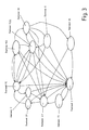
- the embodiment shown in Figure 1 has one Hardware part 1 and a software part 2.
- To the hardware part 1 include the transmission 3, the clutch 4, e.g. a hydraulic Wet clutch with return spring, also a control valve 5, e.g. a proportional valve and a variable one Control magnet 6.
- a certain hydraulic pressure on the clutch 4 which in turn causes the transmission or the clutch slip of the transmission 3 is affected becomes.
- the transmission is based on the engine speed before Clutch 4 and the primary speed or the transmission input speed determined behind the clutch 4. The difference from These two speeds determine the current clutch slip.
- This clutch slip represents a possible actual value for a clutch control.
- the slip control is the upper control block 7 of the software part in FIG. 1 2.
- the lower control block 8 provides engine speed control represents.
- the slip control 7 has a PID controller 9, which the Gear 3 both the engine speed 10 and the transmission input speed 11 is fed, this feed can be interrupted with a switch 12. From the difference between engine speed 10 and transmission input speed 11 the current clutch slip is calculated.
- the PID controller 9 is also a setpoint 13 for a Clutch slip rate or a clutch slip setpoint fed, which also directly an inverse feed-forward model 14 are fed to the clutch control. Also these leads can be interrupted by switches 15 and 16 become.
- the hydraulic pressure is between the control valve 5 and the clutch 4 queried, and a corresponding signal 17th is also passed to the inverse feed forward model 14.
- a corresponding signal 17th is also passed to the inverse feed forward model 14.
- the inverse feed-forward model 14 can still more Control variables 18 received, the different clutch states represent.
- the software part 2 also contains a real-time torque calculation 19, in which a number of suitable parameters 20 for the engine operating condition, e.g. Ignition timing and Air / fuel ratio.
- the real-time engine torque is also the inverse for the slip control 7 Feed-forward model 14 fed.
- the engine speed control 8 also has a PID controller 21 on.
- the engine speed 22 is supplied to it by the transmission 3, the corresponding line through a switch 23 can be interrupted.
- the PID controller 21 will also a target engine speed 24 is supplied.
- the initial size of the PID controller 8 is a signal for an engine torque 25.
- the calculated real-time torque is also used to control the engine speed 8 forwarded.
- the lines from the PID controller 21 and from the real-time torque calculation 19 to the inverse feed-forward model can be interrupted with two switches 27 and 27a.
- the inverse feed forward model 14 determines from it supplied by the slip or engine speed control 7, 8 Data a target current 28, which it the variable Control magnet 6 supplies. Actuated due to the target current 28 the control magnet 6, the control valve 5 to a predetermined To generate hydraulic pressure on the clutch 4.
- the inverse feed-forward model 14 used is a further development the feed-forward strategy. With the feed-forward strategy a certain proportion of the target size becomes direct given on the manipulated variable. The remaining portion of the The setpoint runs through a conventional control loop. However, this only works satisfactorily if the one given directly to the controller output Input size with the right size and the right one Direction works. This requires impact the actual variable change to the manipulated variable as precisely as possible to know in advance.
- the inverse feed-forward model is used for this 14 of the clutch control shown.
- the inverse Feed-forward model 14 calculates the characteristic of the control magnet 6, the control valve 5, the hydraulics 29 and the Clutch 4 reverse, i.e. it simulates the transfer function the controlled system in an inverse manner. Along with the controlled system thus results in a transfer function of almost one. Due to model inaccuracies, for example an unconsidered clutch aging however, a feedback scheme continues in certain Operating modes necessary, but only errors are corrected and no longer the entire target size.
- FIG. 2 shows the inverse feed-forward model 14 in more detail. It includes blocks I to V, each different physical aspects of the clutch are simulated.
- Block II contains the clutch model in which the target torque 31 also entered bypassing block I directly can be.
- Other input variables are a control variable 32 for the brake-away control, which is below is a control variable 33 for the ramp of the Torque control with clutch closed (will also explained in more detail below) and a tax variable 34 for pump losses.
- the latter tax variable 34 is the Block II fed from block III.
- block II the required Coupling pressure calculated at a desired torque. The geometry of the coupling and the static and dynamic friction coefficient of the clutch taken into account.
- So-called pump losses 34 are calculated in block III are transmitted as an output variable to block II.
- Pump losses are among others speed and temperature dependent Fluctuations in clutch fluid flow and fluctuations taken into account in the fluid supply system, which for the Generation of a desired clutch pressure required Influence valve position and therefore in the feed-forward model are to be considered.
- Block IV contains a control valve model.
- Block IV receives from Block II is the input variable to be set by the control valve Clutch pressure 35, i.e. the one to be set on the clutch Hydraulic pressure.
- Other input variables are a Signal 36 from an optional pressure sensor and signal 37 for the open-loop pressure ramp with the clutch open (will continue explained in more detail below).
- Block IV is essentially implements a table or function that the to be controlled Position of the valve for a desired clutch pressure contains. This essentially depends on the geometry of the valve from.
- Block V contains the model for the variable control magnet 6 and receives a control signal as an input variable from block IV 38 for the hydraulic pressure to be set.
- Initial size of the Blocks V is the required target current to be applied 28. In this block thus becomes the nonlinear characteristic of the variable Control magnet compensated.
- State II represents a creep mode without torque transmission (Low creep), i.e. the vehicle is stationary. At a Gear lever change from P or also from N (idle) to D target the creep mode does not start with too much delay. Due to the finite length of the hydraulic line 29 from Control valve 5 to clutch 4 and due to the ventilation this hydraulic line 29 with a longer disengagement time, A hydraulic oil column must first be used to effect clutch pressure be built up, resulting in said delay leads.
- the courses of five are characteristic in FIG Sizes shown over time. To these characteristic Sizes include clutch pressure A, timer B, a calculated clutch torque C on the control solenoids D applied target current 0 and the position of the gear selector lever E.
- the gear selector lever E is located between the times t0 and t1 to N, the target current D is for closing the control valve 5 large, the calculated or target clutch torque C. 0, timer B is at 0 and clutch pressure A is also to 0.
- gear selector lever E is shifted from N to D. to reduce the delay due to construction the hydraulic oil column according to the invention for a so-called Blip-Time 39 between t1 and t2 a high arithmetic Coupling torque 40 given to the clutch control.
- the clutch control leaves the clutch pressure A in a pure open loop control can rise very high.
- This is purely timer-controlled as long (in the example shown up to time t2) until after experience has built up sufficient pressure without the clutch 4 engages to prevent the engine stalling.
- the Blip-Time 39 or the set duration of the timer depends on the temperature, to the temperature dependent viscosity of the Hydraulic oil to be considered.
- Creep high creep, condition IV
- This Creeping can be done open-loop, i.e. with one certain transmission factor so that the vehicle is dependent of gradient, temperature, etc. at different speeds creeps.
- This option is based on a given Clutch pressure regulated. But it is also an engine speed control 8 closed-loop according to Figure 1 possible, so that Vehicle always crawls at the same speed. It is also conceivable that the driver is between regulated and unregulated creep can choose. It is also conceivable that the driver Crawl can completely turn off via a switch. in the State IV will be blocks II to V of the inverse feed-forward model 14 executed.
- the state X represents a feature that the driving comfort in increased in a special way.
- Starting from state X only can be activated by state IX in two ways: once by a so-called "tip in", i.e. an abrupt Depress the accelerator pedal or release suddenly of the accelerator pedal, causing rapid changes in throttle position and secondly due to very low vehicle speeds, where the fully closed Clutch choking the engine would be feared as for example when rolling out the vehicle.
- tip in i.e. an abrupt Depress the accelerator pedal or release suddenly of the accelerator pedal, causing rapid changes in throttle position and secondly due to very low vehicle speeds, where the fully closed Clutch choking the engine would be feared as for example when rolling out the vehicle.
- To beat in To prevent the drivetrain or stalling is used in this Condition creates an artificial clutch slip (so-called. Brake-away control). This can be done through special regular measures are generated by the clutch 4 a little is opened.
- state XI can still be approached be below a given vehicle speed is activated.
- the clutch pressure is in state XI not immediately moved to zero to close the clutch open, but there is a defined ramp open-loop of at an initially higher set pressure to produce a reproducible feeling when disengaging. Therefor only blocks IV and V of the inverse feed-forward model 14 used.
Landscapes
- Engineering & Computer Science (AREA)
- General Engineering & Computer Science (AREA)
- Physics & Mathematics (AREA)
- Fluid Mechanics (AREA)
- Mechanical Engineering (AREA)
- Hydraulic Clutches, Magnetic Clutches, Fluid Clutches, And Fluid Joints (AREA)
Claims (6)
- Procédé de commande automatique d'un embrayage répercutant, sur une transmission, un couple de rotation développé par un moteur, dans lequel
un patinage d'accouplement est déterminé à partir de la différence entre la vitesse angulaire (10) du moteur et la vitesse angulaire d'entrée (11) de la transmission,
le couple de rotation est répercuté sans patinage, par l'embrayage (4), en mode déplacement normal, et
un patinage d'accouplement artificiel est immédiatement engendré lors de variations brusques de la charge, puis est ensuite progressivement ramené vers zéro, caractérisé par le fait que
l'embrayage est exclusivement piloté par un modèle inverse "feed-forward" (14) qui détermine, en fonction d'un patinage d'accouplement souhaité, la pression d'accouplement devant être exercée sur ledit embrayage au moyen d'un organe de réglage. - Procédé selon la revendication 1, caractérisé par le fait que les variations brusques de la charge sont repérées sur la base d'une modification rapide de la position d'un élément de commande de puissance du moteur.
- Procédé selon 1a revendication 1 ou 2, caractérisé par le fait qu'un patinage d'accouplement artificiel est additionnellement engendré à de très faibles vitesses angulaires du moteur.
- Procédé selon l'une des revendications 1 à 3, caractérisé par le fait que la pression d'accouplement est réglée en mode déplacement normal exempt de patinage, par l'intermédiaire du modèle inverse "feed-forward", sur une pression avoisinant la pression minimale pour l'absence de patinage, à laquelle s'ajoute un facteur de sûreté.
- Procédé selon l'une des revendications 1 à 4, caractérisé par le fait que la valeur de la friction de l'embrayage (4) est entrée dans le modèle inverse "feed-forward" (14); et par le fait que le patinage d'accouplement artificiel est engendré par accroissement de ladite valeur de friction.
- Procédé selon l'une des revendications 1 à 5, caractérisé par le fait que, après génération du patinage d'accouplement artificiel, une régulation de rétrocouplage est exécutée par l'intermédiaire du modèle inverse "feed-forward", avec la valeur de consigne "0" du patinage, jusqu'à ce que l'absence de patinage soit atteinte.
Priority Applications (3)
| Application Number | Priority Date | Filing Date | Title |
|---|---|---|---|
| DE59903970T DE59903970D1 (de) | 1999-06-04 | 1999-06-04 | Steuerung für eine fluidbetätigte Kupplung |
| EP99110762A EP1058019B1 (fr) | 1999-06-04 | 1999-06-04 | Commande pour un embrayage actionné par fluide |
| JP2000165541A JP2001012517A (ja) | 1999-06-04 | 2000-06-02 | 流体作動クラッチの制御 |
Applications Claiming Priority (1)
| Application Number | Priority Date | Filing Date | Title |
|---|---|---|---|
| EP99110762A EP1058019B1 (fr) | 1999-06-04 | 1999-06-04 | Commande pour un embrayage actionné par fluide |
Publications (2)
| Publication Number | Publication Date |
|---|---|
| EP1058019A1 EP1058019A1 (fr) | 2000-12-06 |
| EP1058019B1 true EP1058019B1 (fr) | 2003-01-08 |
Family
ID=8238290
Family Applications (1)
| Application Number | Title | Priority Date | Filing Date |
|---|---|---|---|
| EP99110762A Expired - Lifetime EP1058019B1 (fr) | 1999-06-04 | 1999-06-04 | Commande pour un embrayage actionné par fluide |
Country Status (3)
| Country | Link |
|---|---|
| EP (1) | EP1058019B1 (fr) |
| JP (1) | JP2001012517A (fr) |
| DE (1) | DE59903970D1 (fr) |
Families Citing this family (7)
| Publication number | Priority date | Publication date | Assignee | Title |
|---|---|---|---|---|
| EP1319138B1 (fr) * | 2000-09-18 | 2006-03-01 | Siemens Aktiengesellschaft | Procede de commande d'un embrayage automatique de vehicule a moteur |
| JP3535140B2 (ja) | 2002-05-23 | 2004-06-07 | 本田技研工業株式会社 | ハイブリッド車両 |
| JP3771213B2 (ja) | 2002-11-19 | 2006-04-26 | 本田技研工業株式会社 | ハイブリッド車両のクラッチ制御装置 |
| WO2011020461A1 (fr) * | 2009-08-20 | 2011-02-24 | Schaeffler Technologies Gmbh & Co. Kg | Procédé de commande d'un système d'embrayage automatisé |
| US8634997B2 (en) | 2011-04-29 | 2014-01-21 | GM Global Technology Operations LLC | Direct clutch control for dual clutch transmissions |
| DE102019102682B4 (de) | 2019-02-04 | 2026-04-30 | Volkswagen Aktiengesellschaft | Verfahren zur Regelung einer nasslaufenden Kupplung eines Kraftfahrzeugs |
| CN117628085A (zh) * | 2022-08-17 | 2024-03-01 | 上海汽车集团股份有限公司 | 一种离合器的压力确定方法及装置 |
Family Cites Families (4)
| Publication number | Priority date | Publication date | Assignee | Title |
|---|---|---|---|---|
| GB8723547D0 (en) * | 1987-10-07 | 1987-11-11 | Automotive Prod Plc | Clutch control |
| DE3918254C2 (de) * | 1988-06-15 | 1998-04-30 | Volkswagen Ag | Verfahren zur Verhinderung von Lastwechselschlägen |
| US5553694A (en) | 1994-10-14 | 1996-09-10 | Ford Motor Company | Multiple ratio automatic transmission and torque converter |
| US5527238A (en) * | 1995-04-10 | 1996-06-18 | Ford Motor Company | Automatic transmission bypass clutch slip control using nonlinear nverse dynamics |
-
1999
- 1999-06-04 EP EP99110762A patent/EP1058019B1/fr not_active Expired - Lifetime
- 1999-06-04 DE DE59903970T patent/DE59903970D1/de not_active Expired - Fee Related
-
2000
- 2000-06-02 JP JP2000165541A patent/JP2001012517A/ja active Pending
Also Published As
| Publication number | Publication date |
|---|---|
| DE59903970D1 (de) | 2003-02-13 |
| EP1058019A1 (fr) | 2000-12-06 |
| JP2001012517A (ja) | 2001-01-16 |
Similar Documents
| Publication | Publication Date | Title |
|---|---|---|
| EP0580827B1 (fr) | Dispositif de reglage du couple de sortie d'une boite de vitesses automatique | |
| DE602004000650T2 (de) | Steuerverfahren für ein Doppelkupplungsgetriebe | |
| DE3045840C2 (fr) | ||
| EP0670789B1 (fr) | Procede permettant de moduler le couple de sortie d'une boite de vitesses automatique | |
| DE69521866T2 (de) | Automatisierte Kupplungsbetätigung und -Einstellung | |
| DE602005003896T2 (de) | Steuervorrichtung zum Steuern eines Motormomentes | |
| DE69905485T2 (de) | Verfahren zur steuerung des motordrehmoments während eines schaltvorganges | |
| DE19837816A1 (de) | Verfahren zum Steuern einer Kupplung | |
| DE10012122A1 (de) | Kupplungssteuersystem | |
| DE19634441C2 (de) | Drucksteuersystem für das Arbeitsfluid in einem automatischen Getriebe zur schnellen und ruckfreien Bewegung eines Schalthebels | |
| EP1564446B1 (fr) | Méthode et dispostif de commande de changement de vitesse pour transmission véhiculaire à changement parallèle | |
| DE19725816A1 (de) | Kraftfahrzeug, sowie ein Verfahren zur Verwendung eines Kraftfahrzeuges | |
| DE10225448A1 (de) | Verfahren und Vorrichtung zur Steuerung der Brennkraftmaschine eines Fahrzeugs | |
| DE19841856C1 (de) | Verfahren zum Durchführen von Schaltprozeduren | |
| EP3277552B1 (fr) | Procédé permettant de faire fonctionner un dispositif d'entraînement pour un véhicule automobile et dispositif d'entraînement correspondant | |
| DE19644286A1 (de) | Herunterschalt-Steuervorrichtung für Automatikgetriebe | |
| EP1181166A1 (fr) | Procede permettant de commander un ensemble d'entrainement d'un systeme d'entrainement sur la base d'un deroulement predictif pour une certaine grandeur de fonctionnement | |
| EP1058019B1 (fr) | Commande pour un embrayage actionné par fluide | |
| WO2017076604A1 (fr) | Procédé et dispositif d'engagement d'une chaîne cinématique dans un fonctionnement en poussée d'un véhicule automobile | |
| DE2447949A1 (de) | Getriebesteuerung | |
| DE10231817A1 (de) | Verfahren zur Steuerung eines Gangwechsels in einem Kraftfahrzeug-Automatgetriebe | |
| WO2016177367A1 (fr) | Procédé de commande de l'embrayage d'un véhicule une fois terminée une marche en roue libre du véhicule | |
| EP1375238B1 (fr) | Commande de couple moteur et d'embrayage en véhicules roulants | |
| DE19949204A1 (de) | Kraftfahrzeug mit Kupplungseinrichtung | |
| EP3232093B1 (fr) | Procédé destiné à réduire au minimum des perturbations dans une chaîne cinématique d'un véhicule automobile lors du changement de vitesses |
Legal Events
| Date | Code | Title | Description |
|---|---|---|---|
| PUAI | Public reference made under article 153(3) epc to a published international application that has entered the european phase |
Free format text: ORIGINAL CODE: 0009012 |
|
| 17P | Request for examination filed |
Effective date: 19991229 |
|
| AK | Designated contracting states |
Kind code of ref document: A1 Designated state(s): DE FR GB IT SE |
|
| AX | Request for extension of the european patent |
Free format text: AL;LT;LV;MK;RO;SI |
|
| AKX | Designation fees paid |
Free format text: DE FR GB IT SE |
|
| 17Q | First examination report despatched |
Effective date: 20011115 |
|
| GRAH | Despatch of communication of intention to grant a patent |
Free format text: ORIGINAL CODE: EPIDOS IGRA |
|
| GRAH | Despatch of communication of intention to grant a patent |
Free format text: ORIGINAL CODE: EPIDOS IGRA |
|
| GRAA | (expected) grant |
Free format text: ORIGINAL CODE: 0009210 |
|
| AK | Designated contracting states |
Kind code of ref document: B1 Designated state(s): DE FR GB IT SE |
|
| PG25 | Lapsed in a contracting state [announced via postgrant information from national office to epo] |
Ref country code: IT Free format text: LAPSE BECAUSE OF FAILURE TO SUBMIT A TRANSLATION OF THE DESCRIPTION OR TO PAY THE FEE WITHIN THE PRE;WARNING: LAPSES OF ITALIAN PATENTS WITH EFFECTIVE DATE BEFORE 2007 MAY HAVE OCCURRED AT ANY TIME BEFORE 2007. THE CORRECT EFFECTIVE DATE MAY BE DIFFERENT FROM THE ONE RECORDED.SCRIBED TIME-LIMIT Effective date: 20030108 |
|
| REG | Reference to a national code |
Ref country code: GB Ref legal event code: FG4D Free format text: NOT ENGLISH |
|
| REF | Corresponds to: |
Ref document number: 59903970 Country of ref document: DE Date of ref document: 20030213 Kind code of ref document: P |
|
| PG25 | Lapsed in a contracting state [announced via postgrant information from national office to epo] |
Ref country code: SE Free format text: LAPSE BECAUSE OF FAILURE TO SUBMIT A TRANSLATION OF THE DESCRIPTION OR TO PAY THE FEE WITHIN THE PRESCRIBED TIME-LIMIT Effective date: 20030408 |
|
| GBT | Gb: translation of ep patent filed (gb section 77(6)(a)/1977) | ||
| REG | Reference to a national code |
Ref country code: FR Ref legal event code: RN |
|
| REG | Reference to a national code |
Ref country code: FR Ref legal event code: FC |
|
| PLBE | No opposition filed within time limit |
Free format text: ORIGINAL CODE: 0009261 |
|
| STAA | Information on the status of an ep patent application or granted ep patent |
Free format text: STATUS: NO OPPOSITION FILED WITHIN TIME LIMIT |
|
| EN | Fr: translation not filed | ||
| PG25 | Lapsed in a contracting state [announced via postgrant information from national office to epo] |
Ref country code: FR Free format text: LAPSE BECAUSE OF FAILURE TO SUBMIT A TRANSLATION OF THE DESCRIPTION OR TO PAY THE FEE WITHIN THE PRESCRIBED TIME-LIMIT Effective date: 20031128 |
|
| ET | Fr: translation filed | ||
| 26N | No opposition filed |
Effective date: 20031009 |
|
| REG | Reference to a national code |
Ref country code: FR Ref legal event code: TP |
|
| REG | Reference to a national code |
Ref country code: GB Ref legal event code: 746 Effective date: 20060420 |
|
| PGFP | Annual fee paid to national office [announced via postgrant information from national office to epo] |
Ref country code: DE Payment date: 20080630 Year of fee payment: 10 |
|
| PGFP | Annual fee paid to national office [announced via postgrant information from national office to epo] |
Ref country code: GB Payment date: 20080506 Year of fee payment: 10 |
|
| GBPC | Gb: european patent ceased through non-payment of renewal fee |
Effective date: 20090604 |
|
| REG | Reference to a national code |
Ref country code: FR Ref legal event code: ST Effective date: 20100226 |
|
| PGFP | Annual fee paid to national office [announced via postgrant information from national office to epo] |
Ref country code: FR Payment date: 20080424 Year of fee payment: 10 |
|
| PG25 | Lapsed in a contracting state [announced via postgrant information from national office to epo] |
Ref country code: GB Free format text: LAPSE BECAUSE OF NON-PAYMENT OF DUE FEES Effective date: 20090604 |
|
| PG25 | Lapsed in a contracting state [announced via postgrant information from national office to epo] |
Ref country code: DE Free format text: LAPSE BECAUSE OF NON-PAYMENT OF DUE FEES Effective date: 20100101 |
|
| PG25 | Lapsed in a contracting state [announced via postgrant information from national office to epo] |
Ref country code: FR Free format text: LAPSE BECAUSE OF FAILURE TO SUBMIT A TRANSLATION OF THE DESCRIPTION OR TO PAY THE FEE WITHIN THE PRESCRIBED TIME-LIMIT Effective date: 20090630 |