EP1058093A1 - Verfahren und Schaltungsanordnung zur Spannungsversorgung und Funktionsüberwachung zumindest eines Messwertumformers - Google Patents
Verfahren und Schaltungsanordnung zur Spannungsversorgung und Funktionsüberwachung zumindest eines Messwertumformers Download PDFInfo
- Publication number
- EP1058093A1 EP1058093A1 EP99110454A EP99110454A EP1058093A1 EP 1058093 A1 EP1058093 A1 EP 1058093A1 EP 99110454 A EP99110454 A EP 99110454A EP 99110454 A EP99110454 A EP 99110454A EP 1058093 A1 EP1058093 A1 EP 1058093A1
- Authority
- EP
- European Patent Office
- Prior art keywords
- voltage
- monitoring
- circuit
- primary frequency
- signals
- Prior art date
- Legal status (The legal status is an assumption and is not a legal conclusion. Google has not performed a legal analysis and makes no representation as to the accuracy of the status listed.)
- Granted
Links
- 238000012544 monitoring process Methods 0.000 title claims description 46
- 238000000034 method Methods 0.000 title claims description 19
- 230000001419 dependent effect Effects 0.000 claims abstract description 16
- 238000005259 measurement Methods 0.000 claims abstract description 15
- 238000011156 evaluation Methods 0.000 claims description 37
- 238000006243 chemical reaction Methods 0.000 claims description 25
- 230000005540 biological transmission Effects 0.000 claims description 9
- 239000000126 substance Substances 0.000 claims description 6
- 230000007257 malfunction Effects 0.000 claims description 4
- 238000012360 testing method Methods 0.000 claims description 3
- 230000005669 field effect Effects 0.000 claims description 2
- 238000004088 simulation Methods 0.000 description 5
- 238000012545 processing Methods 0.000 description 3
- 230000009467 reduction Effects 0.000 description 3
- 239000003990 capacitor Substances 0.000 description 2
- 238000001514 detection method Methods 0.000 description 2
- 238000005516 engineering process Methods 0.000 description 2
- 231100001261 hazardous Toxicity 0.000 description 2
- 238000012546 transfer Methods 0.000 description 2
- 230000006978 adaptation Effects 0.000 description 1
- 230000015572 biosynthetic process Effects 0.000 description 1
- 230000007423 decrease Effects 0.000 description 1
- 230000005611 electricity Effects 0.000 description 1
- 238000004880 explosion Methods 0.000 description 1
- 239000002360 explosive Substances 0.000 description 1
- 238000002955 isolation Methods 0.000 description 1
- 238000002360 preparation method Methods 0.000 description 1
- 230000008054 signal transmission Effects 0.000 description 1
- 238000011144 upstream manufacturing Methods 0.000 description 1
Images
Classifications
-
- G—PHYSICS
- G01—MEASURING; TESTING
- G01R—MEASURING ELECTRIC VARIABLES; MEASURING MAGNETIC VARIABLES
- G01R19/00—Arrangements for measuring currents or voltages or for indicating presence or sign thereof
- G01R19/25—Arrangements for measuring currents or voltages or for indicating presence or sign thereof using digital measurement techniques
- G01R19/252—Arrangements for measuring currents or voltages or for indicating presence or sign thereof using digital measurement techniques using analogue/digital converters of the type with conversion of voltage or current into frequency and measuring of this frequency
-
- G—PHYSICS
- G01—MEASURING; TESTING
- G01D—MEASURING NOT SPECIALLY ADAPTED FOR A SPECIFIC VARIABLE; ARRANGEMENTS FOR MEASURING TWO OR MORE VARIABLES NOT COVERED IN A SINGLE OTHER SUBCLASS; TARIFF METERING APPARATUS; MEASURING OR TESTING NOT OTHERWISE PROVIDED FOR
- G01D3/00—Indicating or recording apparatus with provision for the special purposes referred to in the subgroups
- G01D3/08—Indicating or recording apparatus with provision for the special purposes referred to in the subgroups with provision for safeguarding the apparatus, e.g. against abnormal operation, against breakdown
-
- G—PHYSICS
- G01—MEASURING; TESTING
- G01R—MEASURING ELECTRIC VARIABLES; MEASURING MAGNETIC VARIABLES
- G01R31/00—Arrangements for testing electric properties; Arrangements for locating electric faults; Arrangements for electrical testing characterised by what is being tested not provided for elsewhere
- G01R31/28—Testing of electronic circuits, e.g. by signal tracer
- G01R31/282—Testing of electronic circuits specially adapted for particular applications not provided for elsewhere
- G01R31/2829—Testing of circuits in sensor or actuator systems
Definitions
- the invention relates to a method for power supply and function monitoring of at least one transducer, especially two-wire transducer in safety-endangered, especially explosion-endangered, (Industrial) areas of e.g. B. chemical plants.
- Such methods are basically from practice known and will be different depending on the reliability Assigned to application classes in DIN V 19250 are described. Otherwise come as a basis for assessment for the TÜV the standards DIN VDE 0160 (04/89) and DIN 0116 (10/89) (section 8.7) in question.
- two-wire transducers are concerned such transducers (e.g. temperature sensors PT 100 or pressure sensors), which in connection with a so-called Two-wire circuit are used.
- Such Two-wire circuit generates when connected to a low impedance Voltage source proportional to the measured variable Electricity.
- appropriate electronics are provided, a minimum current is required to supply them. Therefore the zero point of such systems has a defined one Value; in many cases it is about 4 mA, while that Nominal signal is approx. 20 mA.
- the measuring span therefore corresponds approx. 16 mA.
- Such signal levels are typical of the Process and control technology and are therefore particularly suitable good for monitoring and processing.
- two-wire systems or circuits can be easily implemented connect electrically.
- the invention is based on the technical problem Method and a circuit arrangement for voltage supply and function monitoring of at least one transducer indicate which one is particularly reliable works and flawless error detection enables so that hereby in particular transducers can be operated, at least the application class AK5 according to DIN V 19250.
- the monitoring / evaluation circuit is already addressed voltage source preferably galvanically isolated executed.
- the two measurement-dependent primary frequency signals are usually independent of each other via a galvanic isolating device from the measurement conversion circuit to the monitoring / evaluation circuit transfer.
- This galvanic isolator can it is an optocoupler or conventional transformers act or transmitter.
- the invention further provides that the output side Measured value voltage additionally in a corresponding Secondary frequency signal is implemented, which with the Primary frequency signals on match or predetermined Dependency is checked.
- the aforementioned test also within selectable limits.
- the invention takes advantage of the fact that two measured value dependent, z. B. measured value proportional, voltage signals usually in a voltage divider two identical (precision) resistors are generated. If there are deviations in the resistance values and thus the Voltage signals occur immediately Deviations in the two corresponding primary frequency signals, the easily in the alternate comparison be recorded in the two computer units. Of course, by doing this, too other errors, for example voltage / frequency converters, determined, which is usually used to implement the measurement-dependent voltage signals in the corresponding Primary frequency signals are used. In any case can be by resorting to the at least two Measured value-dependent voltage signals and their separate processing and transmission to the monitoring / evaluation circuit and the comparison there is already extraordinary achieve great error and functional reliability.
- a defined reduction of the secondary frequency signal is carried out at Preparation and comparison of the two primary frequency signals exclude any errors that occur can.
- This defined reduction in the secondary frequency signal is usually from the two computing units carried out alternately and subjected to a comparison. If the same frequency reductions are detected here, it can be assumed that the monitoring / evaluation circuit (and also the measurement conversion circuit) reliable works.
- the conversion of the measurement-dependent voltage signals into the primary frequency signals and the implementation of the output side Measured value voltage in the secondary frequency signal offers the advantage that on the one hand such (digital) frequency signals reliably and precisely in computer units Agreement or predefined dependency checked and on the other hand a simple transfer of the measured value conversion circuit to the monitoring / evaluation circuit succeed through the galvanic isolating device.
- the term "measured value-dependent voltage signals" is intended in The scope of the invention express that the measurement circuit Voltage signals generated over a certain Correlate the dependency with the measured value. This can be a quadratic dependency act, which is unusual. Because usually linear dependencies are set so that measured values are proportional Voltage signals are generated. This is - as I said - but not mandatory. The same applies naturally also when converting the voltage signals into the primary frequency signals or in the secondary frequency signal. Because here too there are deviations from the majority linear dependency conceivable as long as the dependency is known and can be evaluated.
- the invention is based on only one Exemplary embodiment illustrating the drawing.
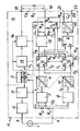
- the only illustration shows a circuit arrangement for power supply and function monitoring at least one transducer, according to the embodiment of a two-wire transducer in hazardous areas Areas of chemical plants.
- the circuit arrangement shown in the single figure is used to connect a two-wire transducer 1 with the to supply the required voltage and at the same time a Complete automatic function monitoring of the voltage supply to guarantee including transducer 1.
- This two-wire transducer 1 has a corresponding one Electronics equipped by a voltage source 2 is powered. Output side of the Transmitter 1 is connected to associated terminals 3, 4 Current dependent on measured value, in the present case proportional to measured value available, which is between approx. 4 mA and approx. 20 mA varies.
- the measuring span of approx. 16 mA corresponds to that Measuring range of the transducer 1, for example the Pressure range between 0 MPa and 1 MPa.
- the transducer 1 together with a transducer circuit M in a safety or explosion hazard Area of a chemical plant is arranged as this through the dash-dotted dividing line to the monitoring / evaluation circuit A was indicated in the supply path to the two-wire transducer 1 a voltage limiter 5 and a current limiter 6, which ensure that, for example, when tearing there is no sparking in a cable. You are for that actual functioning of the circuit arrangement according to the invention of minor importance and pose only the intrinsic safety of the in the potentially explosive Area via terminals 3, 4 to the transducer guided circuit safely.
- the voltage source 2 is galvanically isolated and is used with a partial voltage source 2a on the one hand to supply the measured value conversion circuit M and with a partial voltage source 2b for the energy supply of the monitoring / evaluation circuit A, which is located in protected areas.
- the supply current for the transducer 1 flows from the partial voltage source 2a via the voltage limiter 5, the current limiter 6, the terminal 3, the transducer 1, the terminal 4 and finally back to the partial voltage source 2a, via the two input resistors R 1 and R 2 , which are present connected as a voltage divider R 1 , R 2 and designed as equivalent precision resistors.
- Both U 1 and U 2 are converted in a subsequent voltage / frequency converter 7, 8 into corresponding (square-wave) frequencies or primary frequency signals f 1 , f 2 (proportional to the measured value).
- These voltage / frequency converters 7, 8 can be designed identically, in which case the voltage / frequency converter 7 generates half the frequency of the voltage / frequency converter 8. This can be attributed to the fact that the voltage / frequency converter 8 evaluates the voltage, which is twice as large as compared to the voltage / frequency converter 7, because the zero point of the voltage U 2 coincides with the maximum value of the voltage U 1 .
- U 1 can assume values between 0.2 V to 1 V, while U 2 then covers the range from approximately 1 V to 1.8 V or 2 V. In any case, this can explain the frequency relationships described.
- the voltage / frequency converter 7 Due to the fact that the voltage / frequency converter 7 generates half the frequency of the voltage / frequency converter 8, a corresponding adaptation must take place in two computer units 11, 12 or microprocessors. This can be done in such a way that, for example, the frequency f 1 generated in the voltage / frequency converter 7 is evaluated by a factor of 2 or the frequency f 2 present on the output side of the voltage / frequency converter 8 is evaluated by a factor of 0.5 before the difference value formation described below takes place .
- the slope of the voltage / frequency converter 8 can also be set to half the slope of the voltage / frequency converter 7. In this case, ideally, (square) frequencies f 1, f 2 of the same frequency (and the same amplitude) can be generated on the output side.
- the voltage / frequency converters 7, 8 may be voltage controlled oscillators (VCO).
- Galvanic isolators 9, 10 are connected to the two aforementioned voltage / frequency converters 7, 8, which ensure the independent transmission of the primary frequency signals f 1 , f 2 generated in this way from the measured value conversion circuit M to the monitoring / evaluation circuit A.
- These galvanic isolating devices 9, 10 can be optocouplers or transmitters, which in any case do not correspond to influencing the respectively transmitted frequency f 1 , f 2 .
- the galvanic isolation at this point and in the area of the voltage source 2 ensures complete independence from, on the one hand, the measured value conversion circuit M and, on the other hand, the monitoring / evaluation circuit A, both in terms of the supply or power supply and the signal transmission.
- the (square) frequencies f 1 , f 2 are evaluated in the two computer units 11, 12 or microprocessors. This is done in such a way that the frequency f- transmitted by the galvanic isolating device 9 is transmitted both to an input E 1 of the computer unit 11 and to an input E 1 of the computer unit 12. The same applies to the second frequency f 2 picked up by the separating device 10, which is read in via corresponding inputs E 2 in the computer unit 11 and in the computer unit 12.
- the frequency f 1 transmitted by means of the galvanic isolating device 9 is converted into a frequency / voltage converter 13 and finally a voltage / current converter 14 into an output current (ideally) corresponding to the input current at the terminals 3, 4 or a measured value voltage U 3 (in Connection with a resistor R 7 ) at terminals 15, 16 converted.
- the measured value current thus provided at the terminals 15, 16 is converted into a (square) frequency in a third voltage / frequency converter 17 (which is provided in addition to the converters 7, 8 already described).
- a fixed resistor or resistor R 3 is provided, which corresponds to R 1 or R 2 , so that comparable voltage drops U 1 , U 2 are implemented by the voltage / frequency converter 17.
- the (rectangular) frequency f 3 emitted by it corresponds to the primary frequency signals f 1 , f 2 read in on the input side of the computer units 11, 12.
- This so-called secondary frequency signal f 3 on the output side of the voltage-frequency converter 17 is read in via inputs E 3 in the computer unit 11 or 12.
- This RS flip-flop 18 which is usually constructed from two NOR gates, assumes a correspondingly changing state at its output Q in a known manner only when the respective input R or S is acted upon alternately. In other words, a (square wave) voltage is present at the output Q of the RS flip-flop 18 only if the frequencies f 1 , f 2 , f 3 on the part of the computer unit 11 and the computer unit 12 are successfully checked alternately.
- This stretching voltage is transmitted to a safety signal device 20 via a further galvanic isolating device 19 and rectified.
- a filter element comprising a resistor R 4 and a capacitor C 1 is provided on the output side of this safety signal device 20, so that a DC voltage is present at associated terminals 21, 22.
- This DC voltage signals the correspondence of the frequencies f 1 , f 2 , f 3 , since a corresponding DC voltage is only generated when the RS flip-flop 18 is clocked accordingly.
- Errors in the area of the transmission / evaluation circuit A can be eliminated by a so-called error simulation, which is described below.
- this error simulation continuously reduces the frequency of the secondary frequency signal f 3 present at the respective input E 3 by connecting switching resistors or resistors R 5 and R 6 to R 3 in parallel . This is done in such a way that the computer units 11, 12 alternately switch the resistors R 5 and R 6 upstream of respective field effect transistors T 1 and T 2 to pass through respective outputs A 2 , so that on the one hand the resistor R 5 parallel to the resistor R 3 and on the other hand the Resistor R 6 is parallel to resistor R 3 .
- the frequency of the secondary frequency signal f 3 drops at the respective input E 3 of the computer unit 11 or 12.
- This frequency drop in the secondary frequency signal f 3 compared to the primary frequency signals f 1 , f 2 is checked in the respective computer unit 11, 12. If both processors or computing units 11, 12 come to a matching result, then - and only then - may e.g. B. the R input of the RS flip-flop 18 can be operated.
- the so-called master / slave concept is followed.
- the computer unit 11 may begin and recognize the fault simulation, for example.
- the computer unit 12 is then asked to carry out the error simulation. If both error determinations are the same, the other processor - in this case the computer unit 12 - is authorized to operate the S input of the RS flip-flop 18, for example. Of course, this is done alternately, like checking the primary frequency signals f 1 , f 2 . Consequently, the RS flip-flop 18 is clocked alternately when the above-described error simulation routine is run successfully, so that the DC voltage signal documenting the correct functioning is present at the outputs 21, 22.
- the primary frequency signals f 1 , f 2 and the secondary frequency signal f 3 are checked for equality within a predetermined tolerance band, whereby the processors 11, 12 are also mutually checked.
- the associated outputs A 1 are only operated if there is a match.
Landscapes
- Physics & Mathematics (AREA)
- General Physics & Mathematics (AREA)
- Electromagnetism (AREA)
- Engineering & Computer Science (AREA)
- General Engineering & Computer Science (AREA)
- Arrangements For Transmission Of Measured Signals (AREA)
Abstract
Description
- einer Meßwertumformschaltung mit Meßwertumformer, welche zumindest zwei meßwertabhängige, z. B. meßwertproportionale, Spannungssignale erzeugt, die in zwei korrespondierende (natürlich auch meßwertabhängige bzw. meßwertproportionale) Primärfrequenzsignale umgewandelt und an eine Überwachungs-/Auswerteschaltung mit Sicherheitssignaleinrichtung übertragen werden, und mit
- einer Spannungsquelle für die Meßwertumformschaltung und die Überwachungs-/Auswerteschaltung,
- wonach die Überwachungs-/Auswerteschaltung wenigstens ein Primärfrequenzsignal in die ausgangsseitige Meßwertspannung umwandelt,
- wonach ferner die Überwachungs-/Auswerteschaltung die beiden Primärfrequenzsignale wechselweise vergleicht und hierzu die beiden Primärfrequenzsignale auf Übereinstimmung oder vorgegebene Abhängigkeit überprüft, und
- wonach die Sicherheitssignaleinrichtung bei Übereinstimmung oder Einhaltung der gegebenen Abhängigkeit der Primärfrequenzsignale - selbstverständlich innerhalb wählbarer Grenzen - zum Zwecke der Dokumentation eines einwandfreien Betriebes angesteuert wird oder ein Alarmsignal abgegeben wird (wenn die Übereinstimmung oder gegebene Abhängigkeit nicht vorliegt).
Claims (10)
- Verfahren zur Spannungsversorgung und Funktionsüberwachung zumindest eines Meßwertumformers (1), insbesondere Zweileiter-Meßwertumformers (1) in sicherheitsgefährdeten Bereichen von z. B. chemischen Anlagen, miteiner Meßwertumformschaltung (M), welche zumindest zwei meßwertabhängige Spannungssignale (U1, U2) erzeugt, die in zwei korrespondierende Primärfrequenzsignale (f1, f2) umgewandelt und an eine Überwachungs-/Auswerteschaltung (A) mit Sicherheitssignaleinrichtung (20) übertragen werden, und miteiner Spannungsquelle (2) für die Meßwertumformschaltung (M) und die Überwachungs-/Auswerteschaltung (A),wonach die Überwachungs-/Auswerteschaltung (A) wenigstens ein Primärfrequenzsignal (f1, f2) in eine ausgangsseitige Meßwertspannung (U3) umwandelt,wonach ferner die Überwachungs-/Auswerteschaltung (A) die beiden Primärfrequenzsignale (f1, f2) wechselweise vergleicht und hierzu die beiden Primärfrequenzsignale (f1, f2) auf Übereinstimmung oder vorgegebener Abhängigkeit überprüft, undwonach die Sicherheitssignaleinrichtung (20) bei Übereinstimmung oder Einhaltung der gegebenen Abhängigkeit zum Zwecke der Dokumentation eines einwandfreien Betriebes angesteuert wird.
- Verfahren nach Anspruch 1, dadurch gekennzeichnet, daß zur Speisung einerseits der Meßwertumformschaltung (M, andererseits der Überwachungs-/Auswerteschaltung (A) die Spannungswelle (2) galvanisch getrennt ausgeführt wird.
- Verfahren nach Anspruch 1 oder 2, dadurch gekennzeichnet, daß die beiden Primärfrequenzsignale (f1, f2) jeweils unabhängig voneinander über eine galvanische Trenneinrichtung (9, 10) von der Meßwertumformschaltung (M) an die Überwachungs-/Auswerteschaltung (A) übertragen werden.
- Verfahren nach einem der Ansprüche 1 bis 3, dadurch gekennzeichnet, daß lediglich eines der beiden an die Überwachungs-/Auswerteschaltung (A) übertragenen Primärfrequenzsignale (f1) in die Meßwertspannung (U3) umgewandelt wird.
- Verfahren nach einem der Ansprüche 1 bis 4, dadurch gekennzeichnet, daß die Meßwertspannung (U3) zusätzlich in ein korrespondierendes Senkundärfrequenzsignal (f3) umgesetzt wird, welches mit den Primärfrequenzsignalen (f1, f2) auf Übereinstimmung oder vorgegebene Abhängigkeit überprüft wird.
- Verfahren nach einem der Ansprüche 1 bis 5, dadurch gekennzeichnet, daß zur Ermittlung einer Fehlübertragung seitens der Meßwertumformschaltung (M) und/oder einer Fehlfunktion der Überwachungs-/Auswerteschaltung (A) eine definierte Absenkung des Sekundärfrequenzsignales (f3) durchgeführt wird.
- Schaltungsanordnung zur Durchführung des Verfahrens nach einem der Ansprüche 1 bis 6, miteiner galvanisch getrennten Spannungsquelle (2) zur unabhängigen Speisung einerseits der Meßwertumformschaltung (M) andererseits der Überwachungsauswerteschaltung (A), wobeidie Meßwertumformschaltung (M) zumindest den Meßwertumformer (1), einen Spannungsteiler (R1, R2) zur Erzeugung der wenigstens zwei meßwertabhängigen Spannungssignale (U1, U2) und wenigstens zwei Spannungs-/Frequenzwandler (7, 8) zur Umsetzung der beiden meßwertabhängigen Spannungssignale (U1, U2) in zwei korrespondierende Primärfrequenzsignale (f1, f2) aufweist, wobei fernerdie Überwachungs-/Auswerteschaltung (A) mit zumindest zwei Rechnereinheiten (11, 12) zum jeweils wechselweisen Vergleich der beiden Primärfrequenzsignale (f1, f2) sowie einer von beiden Rechnereinheiten (11, 12) gesteuerten Sicherheitssignaleinrichtung (20) ausgerüstet ist und einen Frequenz-Spannungswandler (13) zur Umsetzung des oder der PrimärFrequenzsignale (f1, f2) in die ausgangsseitige Meßwertspannung (U3) aufweist, und wobeieine galvanische Trenneinrichtung (9, 10) jeweils zwischen Meßwertumformschaltung (M) und Überwachungs/Auswerteschaltung (A) zur Übertragung der Primärfrequenzsignale (f1, f2) vorgesehen ist.
- Schaltungsanordnung nach Anspruch 7, dadurch gekennzeichnet, daß die beiden Rechnereinheiten (11, 12) in Abhängigkeit von der Prüfung der beiden Primärfrequenzsignale (f1, f2) jeweils einen Eingang einer Kippschaltung, z. B. RS-Flip-Flop (18), zur vorzugsweisen Erzeugung einer Gleichspannung im Zuge der Dokumentation des einwandfreien Betriebes mittels der Sicherheitssignaleinrichtung (20) ansteuern.
- Schaltungsanordnung nach Anspruch 7 oder 8, dadurch gekennzeichnet, daß zusätzlich ein dritter Spannungs-/Frequenzwandler (17) in der Überwachungs-/Auswerteschaltung (A) vorgesehen ist, welcher ausgangsseitig das Senkundärfrequenzsignal (f3) erzeugt, welches in den beiden Rechnereinheiten (11, 12) auf Übereinstimmung mit den Primärfrequenzsignalen (f1, f2) überprüft wird.
- Schaltungsanordnung nach einem der Ansprüche 7 bis 9, dadurch gekennzeichnet, daß zur Fehlersimulation und Absenkung der Frequenz des Sekundärfrequenzsignales (f3) von den Rechnereinheiten (11, 12) beaufschlagbare Schalteinrichtungen, z. B. Feldeffekttransistoren (T1, T2) vorgesehen sind, welche jeweils Zuschaltwiderstände (R5, R6) einem Festwiderstand (R3) parallel schalten, der für den zur Erzeugung des Senkundärfrequenzsignales (f3) mit Hilfe des dritten Spannungs-Frequenzwandlers (17) erforderlichen Spannungsabfall sorgt.
Priority Applications (2)
| Application Number | Priority Date | Filing Date | Title |
|---|---|---|---|
| DE59904155T DE59904155D1 (de) | 1999-05-29 | 1999-05-29 | Verfahren und Schaltungsanordnung zur Spannungsversorgung und Funktionsüberwachung zumindest eines Messwertumformers |
| EP19990110454 EP1058093B1 (de) | 1999-05-29 | 1999-05-29 | Verfahren und Schaltungsanordnung zur Spannungsversorgung und Funktionsüberwachung zumindest eines Messwertumformers |
Applications Claiming Priority (1)
| Application Number | Priority Date | Filing Date | Title |
|---|---|---|---|
| EP19990110454 EP1058093B1 (de) | 1999-05-29 | 1999-05-29 | Verfahren und Schaltungsanordnung zur Spannungsversorgung und Funktionsüberwachung zumindest eines Messwertumformers |
Publications (2)
| Publication Number | Publication Date |
|---|---|
| EP1058093A1 true EP1058093A1 (de) | 2000-12-06 |
| EP1058093B1 EP1058093B1 (de) | 2003-01-29 |
Family
ID=8238262
Family Applications (1)
| Application Number | Title | Priority Date | Filing Date |
|---|---|---|---|
| EP19990110454 Expired - Lifetime EP1058093B1 (de) | 1999-05-29 | 1999-05-29 | Verfahren und Schaltungsanordnung zur Spannungsversorgung und Funktionsüberwachung zumindest eines Messwertumformers |
Country Status (2)
| Country | Link |
|---|---|
| EP (1) | EP1058093B1 (de) |
| DE (1) | DE59904155D1 (de) |
Cited By (52)
| Publication number | Priority date | Publication date | Assignee | Title |
|---|---|---|---|---|
| US6356191B1 (en) | 1999-06-17 | 2002-03-12 | Rosemount Inc. | Error compensation for a process fluid temperature transmitter |
| US6370448B1 (en) | 1997-10-13 | 2002-04-09 | Rosemount Inc. | Communication technique for field devices in industrial processes |
| US6397114B1 (en) | 1996-03-28 | 2002-05-28 | Rosemount Inc. | Device in a process system for detecting events |
| US6434504B1 (en) | 1996-11-07 | 2002-08-13 | Rosemount Inc. | Resistance based process control device diagnostics |
| US6449574B1 (en) | 1996-11-07 | 2002-09-10 | Micro Motion, Inc. | Resistance based process control device diagnostics |
| US6473710B1 (en) | 1999-07-01 | 2002-10-29 | Rosemount Inc. | Low power two-wire self validating temperature transmitter |
| US6505517B1 (en) | 1999-07-23 | 2003-01-14 | Rosemount Inc. | High accuracy signal processing for magnetic flowmeter |
| US6735484B1 (en) | 2000-09-20 | 2004-05-11 | Fargo Electronics, Inc. | Printer with a process diagnostics system for detecting events |
| US6754601B1 (en) | 1996-11-07 | 2004-06-22 | Rosemount Inc. | Diagnostics for resistive elements of process devices |
| US6772036B2 (en) | 2001-08-30 | 2004-08-03 | Fisher-Rosemount Systems, Inc. | Control system using process model |
| US6859755B2 (en) | 2001-05-14 | 2005-02-22 | Rosemount Inc. | Diagnostics for industrial process control and measurement systems |
| US6907383B2 (en) | 1996-03-28 | 2005-06-14 | Rosemount Inc. | Flow diagnostic system |
| US6920799B1 (en) | 2004-04-15 | 2005-07-26 | Rosemount Inc. | Magnetic flow meter with reference electrode |
| US6970003B2 (en) | 2001-03-05 | 2005-11-29 | Rosemount Inc. | Electronics board life prediction of microprocessor-based transmitters |
| US7010459B2 (en) | 1999-06-25 | 2006-03-07 | Rosemount Inc. | Process device diagnostics using process variable sensor signal |
| US7018800B2 (en) | 2003-08-07 | 2006-03-28 | Rosemount Inc. | Process device with quiescent current diagnostics |
| US7046180B2 (en) | 2004-04-21 | 2006-05-16 | Rosemount Inc. | Analog-to-digital converter with range error detection |
| US7085610B2 (en) | 1996-03-28 | 2006-08-01 | Fisher-Rosemount Systems, Inc. | Root cause diagnostics |
| US7254518B2 (en) | 1996-03-28 | 2007-08-07 | Rosemount Inc. | Pressure transmitter with diagnostics |
| US7290450B2 (en) | 2003-07-18 | 2007-11-06 | Rosemount Inc. | Process diagnostics |
| US7321846B1 (en) | 2006-10-05 | 2008-01-22 | Rosemount Inc. | Two-wire process control loop diagnostics |
| WO2008135397A1 (de) | 2007-05-03 | 2008-11-13 | Endress+Hauser (Deutschland) Ag+Co. Kg | Verfahren zum inbetriebnehmen und/oder rekonfigurieren eines programmierbaren feldmessgeräts |
| US7523667B2 (en) | 2003-12-23 | 2009-04-28 | Rosemount Inc. | Diagnostics of impulse piping in an industrial process |
| DE102007058608A1 (de) | 2007-12-04 | 2009-06-10 | Endress + Hauser Flowtec Ag | Elektrisches Gerät |
| US7590511B2 (en) | 2007-09-25 | 2009-09-15 | Rosemount Inc. | Field device for digital process control loop diagnostics |
| DE102008022373A1 (de) | 2008-05-06 | 2009-11-12 | Endress + Hauser Flowtec Ag | Meßgerät sowie Verfahren zum Überwachen eines Meßgeräts |
| US7623932B2 (en) | 1996-03-28 | 2009-11-24 | Fisher-Rosemount Systems, Inc. | Rule set for root cause diagnostics |
| US7627441B2 (en) | 2003-09-30 | 2009-12-01 | Rosemount Inc. | Process device with vibration based diagnostics |
| US7630861B2 (en) | 1996-03-28 | 2009-12-08 | Rosemount Inc. | Dedicated process diagnostic device |
| DE102008036552A1 (de) * | 2008-08-06 | 2010-02-18 | Endress + Hauser Gmbh + Co. Kg | Feldgerät der Prozessautomatisierung |
| US7750642B2 (en) | 2006-09-29 | 2010-07-06 | Rosemount Inc. | Magnetic flowmeter with verification |
| US7835295B2 (en) | 2005-07-19 | 2010-11-16 | Rosemount Inc. | Interface module with power over Ethernet function |
| US7921734B2 (en) | 2009-05-12 | 2011-04-12 | Rosemount Inc. | System to detect poor process ground connections |
| US7940189B2 (en) | 2005-09-29 | 2011-05-10 | Rosemount Inc. | Leak detector for process valve |
| US7949495B2 (en) | 1996-03-28 | 2011-05-24 | Rosemount, Inc. | Process variable transmitter with diagnostics |
| US7953501B2 (en) | 2006-09-25 | 2011-05-31 | Fisher-Rosemount Systems, Inc. | Industrial process control loop monitor |
| DE202010006553U1 (de) | 2010-05-06 | 2011-10-05 | Endress + Hauser Flowtec Ag | Elektronisches Meßgerät mit einem Optokoppler |
| WO2011131399A1 (de) | 2010-04-19 | 2011-10-27 | Endress+Hauser Flowtec Ag | Treiberschaltung für einen messwandler sowie damit gebildetes messsystem |
| DE102010030924A1 (de) | 2010-06-21 | 2011-12-22 | Endress + Hauser Flowtec Ag | Elektronik-Gehäuse für ein elektronisches Gerät bzw. damit gebildetes Gerät |
| US8112565B2 (en) | 2005-06-08 | 2012-02-07 | Fisher-Rosemount Systems, Inc. | Multi-protocol field device interface with automatic bus detection |
| US8290721B2 (en) | 1996-03-28 | 2012-10-16 | Rosemount Inc. | Flow measurement diagnostics |
| DE102011076838A1 (de) | 2011-05-31 | 2012-12-06 | Endress + Hauser Flowtec Ag | Meßgerät-Elektronik für ein Meßgerät-Gerät sowie damit gebildetes Meßgerät-Gerät |
| US8788070B2 (en) | 2006-09-26 | 2014-07-22 | Rosemount Inc. | Automatic field device service adviser |
| US8898036B2 (en) | 2007-08-06 | 2014-11-25 | Rosemount Inc. | Process variable transmitter with acceleration sensor |
| US9052240B2 (en) | 2012-06-29 | 2015-06-09 | Rosemount Inc. | Industrial process temperature transmitter with sensor stress diagnostics |
| US9207670B2 (en) | 2011-03-21 | 2015-12-08 | Rosemount Inc. | Degrading sensor detection implemented within a transmitter |
| US9207129B2 (en) | 2012-09-27 | 2015-12-08 | Rosemount Inc. | Process variable transmitter with EMF detection and correction |
| US9602122B2 (en) | 2012-09-28 | 2017-03-21 | Rosemount Inc. | Process variable measurement noise diagnostic |
| US9634858B2 (en) | 2005-07-20 | 2017-04-25 | Rosemount Inc. | Field device with power over Ethernet |
| DE102016114860A1 (de) | 2016-08-10 | 2018-02-15 | Endress + Hauser Flowtec Ag | Treiberschaltung sowie damit gebildete Umformer-Elektronik bzw. damit gebildetes Meßsystem |
| EP3686558A1 (de) * | 2019-01-28 | 2020-07-29 | Melexis Bulgaria Ltd. | Sensorvorrichtung |
| WO2024022656A1 (de) | 2022-07-29 | 2024-02-01 | Endress+Hauser Flowtec | Anschlussschaltung für ein feldgerät und feldgerät |
Families Citing this family (9)
| Publication number | Priority date | Publication date | Assignee | Title |
|---|---|---|---|---|
| US6539267B1 (en) | 1996-03-28 | 2003-03-25 | Rosemount Inc. | Device in a process system for determining statistical parameter |
| US6654697B1 (en) | 1996-03-28 | 2003-11-25 | Rosemount Inc. | Flow measurement with diagnostics |
| US6519546B1 (en) | 1996-11-07 | 2003-02-11 | Rosemount Inc. | Auto correcting temperature transmitter with resistance based sensor |
| US6601005B1 (en) | 1996-11-07 | 2003-07-29 | Rosemount Inc. | Process device diagnostics using process variable sensor signal |
| US6615149B1 (en) | 1998-12-10 | 2003-09-02 | Rosemount Inc. | Spectral diagnostics in a magnetic flow meter |
| US6611775B1 (en) | 1998-12-10 | 2003-08-26 | Rosemount Inc. | Electrode leakage diagnostics in a magnetic flow meter |
| US6701274B1 (en) | 1999-08-27 | 2004-03-02 | Rosemount Inc. | Prediction of error magnitude in a pressure transmitter |
| US6556145B1 (en) | 1999-09-24 | 2003-04-29 | Rosemount Inc. | Two-wire fluid temperature transmitter with thermocouple diagnostics |
| US6629059B2 (en) | 2001-05-14 | 2003-09-30 | Fisher-Rosemount Systems, Inc. | Hand held diagnostic and communication device with automatic bus detection |
Citations (2)
| Publication number | Priority date | Publication date | Assignee | Title |
|---|---|---|---|---|
| GB2227383A (en) * | 1986-05-28 | 1990-07-25 | Marconi Instruments Ltd | Measuring a frequency signal |
| DE19629934A1 (de) * | 1995-12-28 | 1997-07-03 | Mitsubishi Electric Corp | Sensor und Sensorsystem |
-
1999
- 1999-05-29 DE DE59904155T patent/DE59904155D1/de not_active Expired - Fee Related
- 1999-05-29 EP EP19990110454 patent/EP1058093B1/de not_active Expired - Lifetime
Patent Citations (2)
| Publication number | Priority date | Publication date | Assignee | Title |
|---|---|---|---|---|
| GB2227383A (en) * | 1986-05-28 | 1990-07-25 | Marconi Instruments Ltd | Measuring a frequency signal |
| DE19629934A1 (de) * | 1995-12-28 | 1997-07-03 | Mitsubishi Electric Corp | Sensor und Sensorsystem |
Cited By (60)
| Publication number | Priority date | Publication date | Assignee | Title |
|---|---|---|---|---|
| US7949495B2 (en) | 1996-03-28 | 2011-05-24 | Rosemount, Inc. | Process variable transmitter with diagnostics |
| US7254518B2 (en) | 1996-03-28 | 2007-08-07 | Rosemount Inc. | Pressure transmitter with diagnostics |
| US6397114B1 (en) | 1996-03-28 | 2002-05-28 | Rosemount Inc. | Device in a process system for detecting events |
| US8290721B2 (en) | 1996-03-28 | 2012-10-16 | Rosemount Inc. | Flow measurement diagnostics |
| US7085610B2 (en) | 1996-03-28 | 2006-08-01 | Fisher-Rosemount Systems, Inc. | Root cause diagnostics |
| US7623932B2 (en) | 1996-03-28 | 2009-11-24 | Fisher-Rosemount Systems, Inc. | Rule set for root cause diagnostics |
| US6907383B2 (en) | 1996-03-28 | 2005-06-14 | Rosemount Inc. | Flow diagnostic system |
| US6532392B1 (en) | 1996-03-28 | 2003-03-11 | Rosemount Inc. | Transmitter with software for determining when to initiate diagnostics |
| US7630861B2 (en) | 1996-03-28 | 2009-12-08 | Rosemount Inc. | Dedicated process diagnostic device |
| US6449574B1 (en) | 1996-11-07 | 2002-09-10 | Micro Motion, Inc. | Resistance based process control device diagnostics |
| US6754601B1 (en) | 1996-11-07 | 2004-06-22 | Rosemount Inc. | Diagnostics for resistive elements of process devices |
| US6434504B1 (en) | 1996-11-07 | 2002-08-13 | Rosemount Inc. | Resistance based process control device diagnostics |
| US6370448B1 (en) | 1997-10-13 | 2002-04-09 | Rosemount Inc. | Communication technique for field devices in industrial processes |
| US6356191B1 (en) | 1999-06-17 | 2002-03-12 | Rosemount Inc. | Error compensation for a process fluid temperature transmitter |
| US7010459B2 (en) | 1999-06-25 | 2006-03-07 | Rosemount Inc. | Process device diagnostics using process variable sensor signal |
| US6473710B1 (en) | 1999-07-01 | 2002-10-29 | Rosemount Inc. | Low power two-wire self validating temperature transmitter |
| US6505517B1 (en) | 1999-07-23 | 2003-01-14 | Rosemount Inc. | High accuracy signal processing for magnetic flowmeter |
| US6735484B1 (en) | 2000-09-20 | 2004-05-11 | Fargo Electronics, Inc. | Printer with a process diagnostics system for detecting events |
| US6970003B2 (en) | 2001-03-05 | 2005-11-29 | Rosemount Inc. | Electronics board life prediction of microprocessor-based transmitters |
| US6859755B2 (en) | 2001-05-14 | 2005-02-22 | Rosemount Inc. | Diagnostics for industrial process control and measurement systems |
| US6772036B2 (en) | 2001-08-30 | 2004-08-03 | Fisher-Rosemount Systems, Inc. | Control system using process model |
| US7290450B2 (en) | 2003-07-18 | 2007-11-06 | Rosemount Inc. | Process diagnostics |
| US7018800B2 (en) | 2003-08-07 | 2006-03-28 | Rosemount Inc. | Process device with quiescent current diagnostics |
| US7627441B2 (en) | 2003-09-30 | 2009-12-01 | Rosemount Inc. | Process device with vibration based diagnostics |
| US7523667B2 (en) | 2003-12-23 | 2009-04-28 | Rosemount Inc. | Diagnostics of impulse piping in an industrial process |
| US6920799B1 (en) | 2004-04-15 | 2005-07-26 | Rosemount Inc. | Magnetic flow meter with reference electrode |
| US7046180B2 (en) | 2004-04-21 | 2006-05-16 | Rosemount Inc. | Analog-to-digital converter with range error detection |
| US8112565B2 (en) | 2005-06-08 | 2012-02-07 | Fisher-Rosemount Systems, Inc. | Multi-protocol field device interface with automatic bus detection |
| US7835295B2 (en) | 2005-07-19 | 2010-11-16 | Rosemount Inc. | Interface module with power over Ethernet function |
| US9634858B2 (en) | 2005-07-20 | 2017-04-25 | Rosemount Inc. | Field device with power over Ethernet |
| US7940189B2 (en) | 2005-09-29 | 2011-05-10 | Rosemount Inc. | Leak detector for process valve |
| US7953501B2 (en) | 2006-09-25 | 2011-05-31 | Fisher-Rosemount Systems, Inc. | Industrial process control loop monitor |
| US8788070B2 (en) | 2006-09-26 | 2014-07-22 | Rosemount Inc. | Automatic field device service adviser |
| US7750642B2 (en) | 2006-09-29 | 2010-07-06 | Rosemount Inc. | Magnetic flowmeter with verification |
| US7321846B1 (en) | 2006-10-05 | 2008-01-22 | Rosemount Inc. | Two-wire process control loop diagnostics |
| WO2008135397A1 (de) | 2007-05-03 | 2008-11-13 | Endress+Hauser (Deutschland) Ag+Co. Kg | Verfahren zum inbetriebnehmen und/oder rekonfigurieren eines programmierbaren feldmessgeräts |
| US8898036B2 (en) | 2007-08-06 | 2014-11-25 | Rosemount Inc. | Process variable transmitter with acceleration sensor |
| US7590511B2 (en) | 2007-09-25 | 2009-09-15 | Rosemount Inc. | Field device for digital process control loop diagnostics |
| DE102007058608A1 (de) | 2007-12-04 | 2009-06-10 | Endress + Hauser Flowtec Ag | Elektrisches Gerät |
| DE102008022373A1 (de) | 2008-05-06 | 2009-11-12 | Endress + Hauser Flowtec Ag | Meßgerät sowie Verfahren zum Überwachen eines Meßgeräts |
| DE102008036552A1 (de) * | 2008-08-06 | 2010-02-18 | Endress + Hauser Gmbh + Co. Kg | Feldgerät der Prozessautomatisierung |
| US7921734B2 (en) | 2009-05-12 | 2011-04-12 | Rosemount Inc. | System to detect poor process ground connections |
| WO2011131399A1 (de) | 2010-04-19 | 2011-10-27 | Endress+Hauser Flowtec Ag | Treiberschaltung für einen messwandler sowie damit gebildetes messsystem |
| DE202010006553U1 (de) | 2010-05-06 | 2011-10-05 | Endress + Hauser Flowtec Ag | Elektronisches Meßgerät mit einem Optokoppler |
| DE102010030924A1 (de) | 2010-06-21 | 2011-12-22 | Endress + Hauser Flowtec Ag | Elektronik-Gehäuse für ein elektronisches Gerät bzw. damit gebildetes Gerät |
| WO2011160949A1 (de) | 2010-06-21 | 2011-12-29 | Endress+Hauser Flowtec Ag | Elektronik-gehäuse für ein elektronisches gerät bzw. damit gebildetes gerät |
| US9207670B2 (en) | 2011-03-21 | 2015-12-08 | Rosemount Inc. | Degrading sensor detection implemented within a transmitter |
| US9109936B2 (en) | 2011-05-31 | 2015-08-18 | Endress + Hauser Flowtec Ag | Measuring device electronics for a measuring device as well as measuring device formed therewith |
| WO2012163608A1 (de) | 2011-05-31 | 2012-12-06 | Endress+Hauser Flowtec Ag | Messgerät-elektronik für ein messgerät-gerät und verfahren zum überprüfen des messgeräts |
| DE102011076838A1 (de) | 2011-05-31 | 2012-12-06 | Endress + Hauser Flowtec Ag | Meßgerät-Elektronik für ein Meßgerät-Gerät sowie damit gebildetes Meßgerät-Gerät |
| US9052240B2 (en) | 2012-06-29 | 2015-06-09 | Rosemount Inc. | Industrial process temperature transmitter with sensor stress diagnostics |
| US9207129B2 (en) | 2012-09-27 | 2015-12-08 | Rosemount Inc. | Process variable transmitter with EMF detection and correction |
| US9602122B2 (en) | 2012-09-28 | 2017-03-21 | Rosemount Inc. | Process variable measurement noise diagnostic |
| DE102016114860A1 (de) | 2016-08-10 | 2018-02-15 | Endress + Hauser Flowtec Ag | Treiberschaltung sowie damit gebildete Umformer-Elektronik bzw. damit gebildetes Meßsystem |
| WO2018028932A1 (de) | 2016-08-10 | 2018-02-15 | Endress+Hauser Flowtec Ag | Treiberschaltung, damit gebildete umformerelektronik und damit gebildetes messsystem |
| EP3686558A1 (de) * | 2019-01-28 | 2020-07-29 | Melexis Bulgaria Ltd. | Sensorvorrichtung |
| CN111486875A (zh) * | 2019-01-28 | 2020-08-04 | 迈来芯保加利亚有限公司 | 传感器设备 |
| US11275129B2 (en) | 2019-01-28 | 2022-03-15 | Melexis Bulgaria Ltd. | Sensor device |
| WO2024022656A1 (de) | 2022-07-29 | 2024-02-01 | Endress+Hauser Flowtec | Anschlussschaltung für ein feldgerät und feldgerät |
| DE102022119145A1 (de) | 2022-07-29 | 2024-02-01 | Endress+Hauser Flowtec Ag | Anschlussschaltung für ein Feldgerät und Feldgerät |
Also Published As
| Publication number | Publication date |
|---|---|
| EP1058093B1 (de) | 2003-01-29 |
| DE59904155D1 (de) | 2003-03-06 |
Similar Documents
| Publication | Publication Date | Title |
|---|---|---|
| EP1058093B1 (de) | Verfahren und Schaltungsanordnung zur Spannungsversorgung und Funktionsüberwachung zumindest eines Messwertumformers | |
| EP0946932A2 (de) | Sensor- und auswertesystem, insbesondere für doppelsensoren zur endlagen- und grenzwerterfassung | |
| EP2378663B1 (de) | Sichere Eingangsschaltung mit einkanaligem Peripherieanschluss für den Eingang eines Bus-Teilnehmers | |
| DE2555603C2 (de) | Sicherheitsschaltung | |
| DE10035174A1 (de) | Peripheriebaustein mit hoher Fehlersicherheit für speicherprogrammierbare Steuerungen | |
| EP0127163B1 (de) | Fehlererkennungsschaltung für parallel auf einen Verbraucher speisende Stromversorgungsgeräte | |
| EP0358887B1 (de) | Messwertgeber-Fehlererkennungsschaltung | |
| DE2903860C2 (de) | Einrichtung zur Gleichstromversorgung eines Verbrauchers und zur gleichzeitigen Informationsübertragung über ein Aderpaar | |
| EP2494534B1 (de) | Sicherheits-kommunikationssystem zur signalisierung von systemzuständen | |
| EP3380852B1 (de) | Induktiver strommesswandler | |
| EP1282859B1 (de) | Peripheriebaustein mit hoher fehlersicherheit für speicherprogrammierbare steuerungen | |
| DE2555594C2 (de) | Sicherheitsschaltung | |
| DE102009029307A1 (de) | Vorrichtung zur Übertragung eines Steuersignals | |
| CH669464A5 (de) | ||
| DE2719223C2 (de) | Anordnung zum Umsetzen von Alarmsignalen zwischen einem digitalen Nachrichtenübertragungssystem und einer zentralen Betriebsüberwachung | |
| DE3342710C1 (de) | Näherungsschalter mit Überwachung der Funktion und Funktionsbereitschaft | |
| EP0222682B1 (de) | Signalübertragungsanordnung für eine Vergleichsschutzeinrichtung | |
| WO2020120117A1 (de) | Online-kontrolle für kondensatoren von kondensatorbänken | |
| EP1091332A1 (de) | Leistungsstarkes doppeltes Zweileiter-Messgerät | |
| DE2148072B2 (de) | Schaltungsanordnung zur Überwachung von binären Signalen auf Antivalenz | |
| DE2034487C3 (de) | Schaltungsanordnung zur Erfassung und Auswertung von Störungen einer Nachrichtenübertragungsanlage | |
| WO2020125996A1 (de) | Verfahren und prüfvorrichtung | |
| DE19847179B4 (de) | Schaltungsanordnung zum Erfassen einer galvanisch getrennten Spannung | |
| EP0143111A1 (de) | Schaltungsanordnung eines Fensterkomparators mit Selbstkontrolle | |
| DE2047147A1 (de) | Einrichtung zum Überwachen von Gleisabschnitten für Eisenbahnverkehrs anlagen |
Legal Events
| Date | Code | Title | Description |
|---|---|---|---|
| PUAI | Public reference made under article 153(3) epc to a published international application that has entered the european phase |
Free format text: ORIGINAL CODE: 0009012 |
|
| 17P | Request for examination filed |
Effective date: 19990529 |
|
| AK | Designated contracting states |
Kind code of ref document: A1 Designated state(s): BE CH DE FR GB IT LI NL |
|
| AX | Request for extension of the european patent |
Free format text: AL;LT;LV;MK;RO;SI |
|
| AKX | Designation fees paid |
Free format text: BE CH DE FR GB IT LI NL |
|
| GRAH | Despatch of communication of intention to grant a patent |
Free format text: ORIGINAL CODE: EPIDOS IGRA |
|
| GRAH | Despatch of communication of intention to grant a patent |
Free format text: ORIGINAL CODE: EPIDOS IGRA |
|
| GRAA | (expected) grant |
Free format text: ORIGINAL CODE: 0009210 |
|
| AK | Designated contracting states |
Designated state(s): BE CH DE FR GB IT LI NL |
|
| PG25 | Lapsed in a contracting state [announced via postgrant information from national office to epo] |
Ref country code: NL Free format text: LAPSE BECAUSE OF FAILURE TO SUBMIT A TRANSLATION OF THE DESCRIPTION OR TO PAY THE FEE WITHIN THE PRESCRIBED TIME-LIMIT Effective date: 20030129 Ref country code: IT Free format text: LAPSE BECAUSE OF FAILURE TO SUBMIT A TRANSLATION OF THE DESCRIPTION OR TO PAY THE FEE WITHIN THE PRESCRIBED TIME-LIMIT;WARNING: LAPSES OF ITALIAN PATENTS WITH EFFECTIVE DATE BEFORE 2007 MAY HAVE OCCURRED AT ANY TIME BEFORE 2007. THE CORRECT EFFECTIVE DATE MAY BE DIFFERENT FROM THE ONE RECORDED. Effective date: 20030129 |
|
| REG | Reference to a national code |
Ref country code: GB Ref legal event code: FG4D Free format text: NOT ENGLISH |
|
| REG | Reference to a national code |
Ref country code: CH Ref legal event code: EP |
|
| REF | Corresponds to: |
Ref document number: 59904155 Country of ref document: DE Date of ref document: 20030306 Kind code of ref document: P |
|
| GBT | Gb: translation of ep patent filed (gb section 77(6)(a)/1977) |
Effective date: 20030429 |
|
| PG25 | Lapsed in a contracting state [announced via postgrant information from national office to epo] |
Ref country code: LI Free format text: LAPSE BECAUSE OF NON-PAYMENT OF DUE FEES Effective date: 20030531 Ref country code: CH Free format text: LAPSE BECAUSE OF NON-PAYMENT OF DUE FEES Effective date: 20030531 Ref country code: BE Free format text: LAPSE BECAUSE OF NON-PAYMENT OF DUE FEES Effective date: 20030531 |
|
| NLV1 | Nl: lapsed or annulled due to failure to fulfill the requirements of art. 29p and 29m of the patents act | ||
| ET | Fr: translation filed | ||
| BERE | Be: lapsed |
Owner name: *MTL INSTRUMENTS G.M.B.H. Effective date: 20030531 |
|
| PLBE | No opposition filed within time limit |
Free format text: ORIGINAL CODE: 0009261 |
|
| STAA | Information on the status of an ep patent application or granted ep patent |
Free format text: STATUS: NO OPPOSITION FILED WITHIN TIME LIMIT |
|
| REG | Reference to a national code |
Ref country code: CH Ref legal event code: PL |
|
| 26N | No opposition filed |
Effective date: 20031030 |
|
| PGFP | Annual fee paid to national office [announced via postgrant information from national office to epo] |
Ref country code: DE Payment date: 20060511 Year of fee payment: 8 |
|
| PGFP | Annual fee paid to national office [announced via postgrant information from national office to epo] |
Ref country code: FR Payment date: 20060519 Year of fee payment: 8 |
|
| PGFP | Annual fee paid to national office [announced via postgrant information from national office to epo] |
Ref country code: GB Payment date: 20060522 Year of fee payment: 8 |
|
| GBPC | Gb: european patent ceased through non-payment of renewal fee |
Effective date: 20070529 |
|
| REG | Reference to a national code |
Ref country code: FR Ref legal event code: ST Effective date: 20080131 |
|
| PG25 | Lapsed in a contracting state [announced via postgrant information from national office to epo] |
Ref country code: DE Free format text: LAPSE BECAUSE OF NON-PAYMENT OF DUE FEES Effective date: 20071201 |
|
| PG25 | Lapsed in a contracting state [announced via postgrant information from national office to epo] |
Ref country code: GB Free format text: LAPSE BECAUSE OF NON-PAYMENT OF DUE FEES Effective date: 20070529 |
|
| PG25 | Lapsed in a contracting state [announced via postgrant information from national office to epo] |
Ref country code: FR Free format text: LAPSE BECAUSE OF NON-PAYMENT OF DUE FEES Effective date: 20070531 |