EP1059432A2 - Cooling apparatus for vehicular engine - Google Patents
Cooling apparatus for vehicular engine Download PDFInfo
- Publication number
- EP1059432A2 EP1059432A2 EP00401583A EP00401583A EP1059432A2 EP 1059432 A2 EP1059432 A2 EP 1059432A2 EP 00401583 A EP00401583 A EP 00401583A EP 00401583 A EP00401583 A EP 00401583A EP 1059432 A2 EP1059432 A2 EP 1059432A2
- Authority
- EP
- European Patent Office
- Prior art keywords
- coolant
- engine
- intercooler
- radiator
- egr
- Prior art date
- Legal status (The legal status is an assumption and is not a legal conclusion. Google has not performed a legal analysis and makes no representation as to the accuracy of the status listed.)
- Granted
Links
- 238000001816 cooling Methods 0.000 title claims abstract description 34
- 239000002826 coolant Substances 0.000 claims abstract description 113
- 239000007789 gas Substances 0.000 description 26
- 239000003507 refrigerant Substances 0.000 description 25
- 238000010438 heat treatment Methods 0.000 description 13
- 239000007788 liquid Substances 0.000 description 8
- 238000010586 diagram Methods 0.000 description 6
- 230000001105 regulatory effect Effects 0.000 description 6
- 238000010248 power generation Methods 0.000 description 4
- 238000007599 discharging Methods 0.000 description 3
- PXHVJJICTQNCMI-UHFFFAOYSA-N Nickel Chemical compound [Ni] PXHVJJICTQNCMI-UHFFFAOYSA-N 0.000 description 2
- 238000004378 air conditioning Methods 0.000 description 2
- 238000010276 construction Methods 0.000 description 2
- 238000005516 engineering process Methods 0.000 description 2
- 229910052751 metal Inorganic materials 0.000 description 2
- 239000002184 metal Substances 0.000 description 2
- OYPRJOBELJOOCE-UHFFFAOYSA-N Calcium Chemical compound [Ca] OYPRJOBELJOOCE-UHFFFAOYSA-N 0.000 description 1
- RYGMFSIKBFXOCR-UHFFFAOYSA-N Copper Chemical compound [Cu] RYGMFSIKBFXOCR-UHFFFAOYSA-N 0.000 description 1
- WHXSMMKQMYFTQS-UHFFFAOYSA-N Lithium Chemical compound [Li] WHXSMMKQMYFTQS-UHFFFAOYSA-N 0.000 description 1
- FYYHWMGAXLPEAU-UHFFFAOYSA-N Magnesium Chemical compound [Mg] FYYHWMGAXLPEAU-UHFFFAOYSA-N 0.000 description 1
- BQCADISMDOOEFD-UHFFFAOYSA-N Silver Chemical compound [Ag] BQCADISMDOOEFD-UHFFFAOYSA-N 0.000 description 1
- 238000007664 blowing Methods 0.000 description 1
- 229910052791 calcium Inorganic materials 0.000 description 1
- 239000011575 calcium Substances 0.000 description 1
- 239000000498 cooling water Substances 0.000 description 1
- 229910052802 copper Inorganic materials 0.000 description 1
- 239000010949 copper Substances 0.000 description 1
- 230000000694 effects Effects 0.000 description 1
- 230000005611 electricity Effects 0.000 description 1
- 239000003792 electrolyte Substances 0.000 description 1
- 230000007613 environmental effect Effects 0.000 description 1
- 150000004820 halides Chemical class 0.000 description 1
- 229910052744 lithium Inorganic materials 0.000 description 1
- 229910052749 magnesium Inorganic materials 0.000 description 1
- 239000011777 magnesium Substances 0.000 description 1
- 229910052759 nickel Inorganic materials 0.000 description 1
- RUOJZAUFBMNUDX-UHFFFAOYSA-N propylene carbonate Chemical compound CC1COC(=O)O1 RUOJZAUFBMNUDX-UHFFFAOYSA-N 0.000 description 1
- 238000005086 pumping Methods 0.000 description 1
- 229910052709 silver Inorganic materials 0.000 description 1
- 239000004332 silver Substances 0.000 description 1
- 239000000126 substance Substances 0.000 description 1
- 239000002918 waste heat Substances 0.000 description 1
Images


Classifications
-
- F—MECHANICAL ENGINEERING; LIGHTING; HEATING; WEAPONS; BLASTING
- F01—MACHINES OR ENGINES IN GENERAL; ENGINE PLANTS IN GENERAL; STEAM ENGINES
- F01P—COOLING OF MACHINES OR ENGINES IN GENERAL; COOLING OF INTERNAL-COMBUSTION ENGINES
- F01P3/00—Liquid cooling
-
- B—PERFORMING OPERATIONS; TRANSPORTING
- B60—VEHICLES IN GENERAL
- B60L—PROPULSION OF ELECTRICALLY-PROPELLED VEHICLES; SUPPLYING ELECTRIC POWER FOR AUXILIARY EQUIPMENT OF ELECTRICALLY-PROPELLED VEHICLES; ELECTRODYNAMIC BRAKE SYSTEMS FOR VEHICLES IN GENERAL; MAGNETIC SUSPENSION OR LEVITATION FOR VEHICLES; MONITORING OPERATING VARIABLES OF ELECTRICALLY-PROPELLED VEHICLES; ELECTRIC SAFETY DEVICES FOR ELECTRICALLY-PROPELLED VEHICLES
- B60L3/00—Electric devices on electrically-propelled vehicles for safety purposes; Monitoring operating variables, e.g. speed, deceleration or energy consumption
- B60L3/0023—Detecting, eliminating, remedying or compensating for drive train abnormalities, e.g. failures within the drive train
- B60L3/0061—Detecting, eliminating, remedying or compensating for drive train abnormalities, e.g. failures within the drive train relating to electrical machines
-
- B—PERFORMING OPERATIONS; TRANSPORTING
- B60—VEHICLES IN GENERAL
- B60L—PROPULSION OF ELECTRICALLY-PROPELLED VEHICLES; SUPPLYING ELECTRIC POWER FOR AUXILIARY EQUIPMENT OF ELECTRICALLY-PROPELLED VEHICLES; ELECTRODYNAMIC BRAKE SYSTEMS FOR VEHICLES IN GENERAL; MAGNETIC SUSPENSION OR LEVITATION FOR VEHICLES; MONITORING OPERATING VARIABLES OF ELECTRICALLY-PROPELLED VEHICLES; ELECTRIC SAFETY DEVICES FOR ELECTRICALLY-PROPELLED VEHICLES
- B60L1/00—Supplying electric power to auxiliary equipment of vehicles
- B60L1/003—Supplying electric power to auxiliary equipment of vehicles to auxiliary motors, e.g. for pumps, compressors
-
- B—PERFORMING OPERATIONS; TRANSPORTING
- B60—VEHICLES IN GENERAL
- B60L—PROPULSION OF ELECTRICALLY-PROPELLED VEHICLES; SUPPLYING ELECTRIC POWER FOR AUXILIARY EQUIPMENT OF ELECTRICALLY-PROPELLED VEHICLES; ELECTRODYNAMIC BRAKE SYSTEMS FOR VEHICLES IN GENERAL; MAGNETIC SUSPENSION OR LEVITATION FOR VEHICLES; MONITORING OPERATING VARIABLES OF ELECTRICALLY-PROPELLED VEHICLES; ELECTRIC SAFETY DEVICES FOR ELECTRICALLY-PROPELLED VEHICLES
- B60L1/00—Supplying electric power to auxiliary equipment of vehicles
- B60L1/02—Supplying electric power to auxiliary equipment of vehicles to electric heating circuits
-
- B—PERFORMING OPERATIONS; TRANSPORTING
- B60—VEHICLES IN GENERAL
- B60L—PROPULSION OF ELECTRICALLY-PROPELLED VEHICLES; SUPPLYING ELECTRIC POWER FOR AUXILIARY EQUIPMENT OF ELECTRICALLY-PROPELLED VEHICLES; ELECTRODYNAMIC BRAKE SYSTEMS FOR VEHICLES IN GENERAL; MAGNETIC SUSPENSION OR LEVITATION FOR VEHICLES; MONITORING OPERATING VARIABLES OF ELECTRICALLY-PROPELLED VEHICLES; ELECTRIC SAFETY DEVICES FOR ELECTRICALLY-PROPELLED VEHICLES
- B60L3/00—Electric devices on electrically-propelled vehicles for safety purposes; Monitoring operating variables, e.g. speed, deceleration or energy consumption
- B60L3/0023—Detecting, eliminating, remedying or compensating for drive train abnormalities, e.g. failures within the drive train
- B60L3/003—Detecting, eliminating, remedying or compensating for drive train abnormalities, e.g. failures within the drive train relating to inverters
-
- B—PERFORMING OPERATIONS; TRANSPORTING
- B60—VEHICLES IN GENERAL
- B60L—PROPULSION OF ELECTRICALLY-PROPELLED VEHICLES; SUPPLYING ELECTRIC POWER FOR AUXILIARY EQUIPMENT OF ELECTRICALLY-PROPELLED VEHICLES; ELECTRODYNAMIC BRAKE SYSTEMS FOR VEHICLES IN GENERAL; MAGNETIC SUSPENSION OR LEVITATION FOR VEHICLES; MONITORING OPERATING VARIABLES OF ELECTRICALLY-PROPELLED VEHICLES; ELECTRIC SAFETY DEVICES FOR ELECTRICALLY-PROPELLED VEHICLES
- B60L3/00—Electric devices on electrically-propelled vehicles for safety purposes; Monitoring operating variables, e.g. speed, deceleration or energy consumption
- B60L3/0023—Detecting, eliminating, remedying or compensating for drive train abnormalities, e.g. failures within the drive train
- B60L3/0046—Detecting, eliminating, remedying or compensating for drive train abnormalities, e.g. failures within the drive train relating to electric energy storage systems, e.g. batteries or capacitors
-
- B—PERFORMING OPERATIONS; TRANSPORTING
- B60—VEHICLES IN GENERAL
- B60L—PROPULSION OF ELECTRICALLY-PROPELLED VEHICLES; SUPPLYING ELECTRIC POWER FOR AUXILIARY EQUIPMENT OF ELECTRICALLY-PROPELLED VEHICLES; ELECTRODYNAMIC BRAKE SYSTEMS FOR VEHICLES IN GENERAL; MAGNETIC SUSPENSION OR LEVITATION FOR VEHICLES; MONITORING OPERATING VARIABLES OF ELECTRICALLY-PROPELLED VEHICLES; ELECTRIC SAFETY DEVICES FOR ELECTRICALLY-PROPELLED VEHICLES
- B60L50/00—Electric propulsion with power supplied within the vehicle
- B60L50/10—Electric propulsion with power supplied within the vehicle using propulsion power supplied by engine-driven generators, e.g. generators driven by combustion engines
- B60L50/16—Electric propulsion with power supplied within the vehicle using propulsion power supplied by engine-driven generators, e.g. generators driven by combustion engines with provision for separate direct mechanical propulsion
-
- B—PERFORMING OPERATIONS; TRANSPORTING
- B60—VEHICLES IN GENERAL
- B60L—PROPULSION OF ELECTRICALLY-PROPELLED VEHICLES; SUPPLYING ELECTRIC POWER FOR AUXILIARY EQUIPMENT OF ELECTRICALLY-PROPELLED VEHICLES; ELECTRODYNAMIC BRAKE SYSTEMS FOR VEHICLES IN GENERAL; MAGNETIC SUSPENSION OR LEVITATION FOR VEHICLES; MONITORING OPERATING VARIABLES OF ELECTRICALLY-PROPELLED VEHICLES; ELECTRIC SAFETY DEVICES FOR ELECTRICALLY-PROPELLED VEHICLES
- B60L58/00—Methods or circuit arrangements for monitoring or controlling batteries or fuel cells, specially adapted for electric vehicles
- B60L58/10—Methods or circuit arrangements for monitoring or controlling batteries or fuel cells, specially adapted for electric vehicles for monitoring or controlling batteries
- B60L58/24—Methods or circuit arrangements for monitoring or controlling batteries or fuel cells, specially adapted for electric vehicles for monitoring or controlling batteries for controlling the temperature of batteries
- B60L58/26—Methods or circuit arrangements for monitoring or controlling batteries or fuel cells, specially adapted for electric vehicles for monitoring or controlling batteries for controlling the temperature of batteries by cooling
-
- B—PERFORMING OPERATIONS; TRANSPORTING
- B60—VEHICLES IN GENERAL
- B60L—PROPULSION OF ELECTRICALLY-PROPELLED VEHICLES; SUPPLYING ELECTRIC POWER FOR AUXILIARY EQUIPMENT OF ELECTRICALLY-PROPELLED VEHICLES; ELECTRODYNAMIC BRAKE SYSTEMS FOR VEHICLES IN GENERAL; MAGNETIC SUSPENSION OR LEVITATION FOR VEHICLES; MONITORING OPERATING VARIABLES OF ELECTRICALLY-PROPELLED VEHICLES; ELECTRIC SAFETY DEVICES FOR ELECTRICALLY-PROPELLED VEHICLES
- B60L58/00—Methods or circuit arrangements for monitoring or controlling batteries or fuel cells, specially adapted for electric vehicles
- B60L58/10—Methods or circuit arrangements for monitoring or controlling batteries or fuel cells, specially adapted for electric vehicles for monitoring or controlling batteries
- B60L58/24—Methods or circuit arrangements for monitoring or controlling batteries or fuel cells, specially adapted for electric vehicles for monitoring or controlling batteries for controlling the temperature of batteries
- B60L58/27—Methods or circuit arrangements for monitoring or controlling batteries or fuel cells, specially adapted for electric vehicles for monitoring or controlling batteries for controlling the temperature of batteries by heating
-
- F—MECHANICAL ENGINEERING; LIGHTING; HEATING; WEAPONS; BLASTING
- F01—MACHINES OR ENGINES IN GENERAL; ENGINE PLANTS IN GENERAL; STEAM ENGINES
- F01P—COOLING OF MACHINES OR ENGINES IN GENERAL; COOLING OF INTERNAL-COMBUSTION ENGINES
- F01P7/00—Controlling of coolant flow
- F01P7/14—Controlling of coolant flow the coolant being liquid
- F01P7/16—Controlling of coolant flow the coolant being liquid by thermostatic control
- F01P7/165—Controlling of coolant flow the coolant being liquid by thermostatic control characterised by systems with two or more loops
-
- F—MECHANICAL ENGINEERING; LIGHTING; HEATING; WEAPONS; BLASTING
- F02—COMBUSTION ENGINES; HOT-GAS OR COMBUSTION-PRODUCT ENGINE PLANTS
- F02B—INTERNAL-COMBUSTION PISTON ENGINES; COMBUSTION ENGINES IN GENERAL
- F02B29/00—Engines characterised by provision for charging or scavenging not provided for in groups F02B25/00, F02B27/00 or F02B33/00 - F02B39/00; Details thereof
- F02B29/04—Cooling of air intake supply
- F02B29/0406—Layout of the intake air cooling or coolant circuit
- F02B29/0437—Liquid cooled heat exchangers
- F02B29/0443—Layout of the coolant or refrigerant circuit
-
- F—MECHANICAL ENGINEERING; LIGHTING; HEATING; WEAPONS; BLASTING
- F02—COMBUSTION ENGINES; HOT-GAS OR COMBUSTION-PRODUCT ENGINE PLANTS
- F02B—INTERNAL-COMBUSTION PISTON ENGINES; COMBUSTION ENGINES IN GENERAL
- F02B29/00—Engines characterised by provision for charging or scavenging not provided for in groups F02B25/00, F02B27/00 or F02B33/00 - F02B39/00; Details thereof
- F02B29/04—Cooling of air intake supply
- F02B29/0493—Controlling the air charge temperature
-
- F—MECHANICAL ENGINEERING; LIGHTING; HEATING; WEAPONS; BLASTING
- F02—COMBUSTION ENGINES; HOT-GAS OR COMBUSTION-PRODUCT ENGINE PLANTS
- F02M—SUPPLYING COMBUSTION ENGINES IN GENERAL WITH COMBUSTIBLE MIXTURES OR CONSTITUENTS THEREOF
- F02M26/00—Engine-pertinent apparatus for adding exhaust gases to combustion-air, main fuel or fuel-air mixture, e.g. by exhaust gas recirculation [EGR] systems
- F02M26/13—Arrangement or layout of EGR passages, e.g. in relation to specific engine parts or for incorporation of accessories
- F02M26/22—Arrangement or layout of EGR passages, e.g. in relation to specific engine parts or for incorporation of accessories with coolers in the recirculation passage
- F02M26/23—Layout, e.g. schematics
- F02M26/28—Layout, e.g. schematics with liquid-cooled heat exchangers
-
- B—PERFORMING OPERATIONS; TRANSPORTING
- B60—VEHICLES IN GENERAL
- B60L—PROPULSION OF ELECTRICALLY-PROPELLED VEHICLES; SUPPLYING ELECTRIC POWER FOR AUXILIARY EQUIPMENT OF ELECTRICALLY-PROPELLED VEHICLES; ELECTRODYNAMIC BRAKE SYSTEMS FOR VEHICLES IN GENERAL; MAGNETIC SUSPENSION OR LEVITATION FOR VEHICLES; MONITORING OPERATING VARIABLES OF ELECTRICALLY-PROPELLED VEHICLES; ELECTRIC SAFETY DEVICES FOR ELECTRICALLY-PROPELLED VEHICLES
- B60L2210/00—Converter types
- B60L2210/10—DC to DC converters
-
- B—PERFORMING OPERATIONS; TRANSPORTING
- B60—VEHICLES IN GENERAL
- B60L—PROPULSION OF ELECTRICALLY-PROPELLED VEHICLES; SUPPLYING ELECTRIC POWER FOR AUXILIARY EQUIPMENT OF ELECTRICALLY-PROPELLED VEHICLES; ELECTRODYNAMIC BRAKE SYSTEMS FOR VEHICLES IN GENERAL; MAGNETIC SUSPENSION OR LEVITATION FOR VEHICLES; MONITORING OPERATING VARIABLES OF ELECTRICALLY-PROPELLED VEHICLES; ELECTRIC SAFETY DEVICES FOR ELECTRICALLY-PROPELLED VEHICLES
- B60L2240/00—Control parameters of input or output; Target parameters
- B60L2240/10—Vehicle control parameters
- B60L2240/34—Cabin temperature
-
- B—PERFORMING OPERATIONS; TRANSPORTING
- B60—VEHICLES IN GENERAL
- B60L—PROPULSION OF ELECTRICALLY-PROPELLED VEHICLES; SUPPLYING ELECTRIC POWER FOR AUXILIARY EQUIPMENT OF ELECTRICALLY-PROPELLED VEHICLES; ELECTRODYNAMIC BRAKE SYSTEMS FOR VEHICLES IN GENERAL; MAGNETIC SUSPENSION OR LEVITATION FOR VEHICLES; MONITORING OPERATING VARIABLES OF ELECTRICALLY-PROPELLED VEHICLES; ELECTRIC SAFETY DEVICES FOR ELECTRICALLY-PROPELLED VEHICLES
- B60L2240/00—Control parameters of input or output; Target parameters
- B60L2240/10—Vehicle control parameters
- B60L2240/36—Temperature of vehicle components or parts
-
- B—PERFORMING OPERATIONS; TRANSPORTING
- B60—VEHICLES IN GENERAL
- B60L—PROPULSION OF ELECTRICALLY-PROPELLED VEHICLES; SUPPLYING ELECTRIC POWER FOR AUXILIARY EQUIPMENT OF ELECTRICALLY-PROPELLED VEHICLES; ELECTRODYNAMIC BRAKE SYSTEMS FOR VEHICLES IN GENERAL; MAGNETIC SUSPENSION OR LEVITATION FOR VEHICLES; MONITORING OPERATING VARIABLES OF ELECTRICALLY-PROPELLED VEHICLES; ELECTRIC SAFETY DEVICES FOR ELECTRICALLY-PROPELLED VEHICLES
- B60L58/00—Methods or circuit arrangements for monitoring or controlling batteries or fuel cells, specially adapted for electric vehicles
- B60L58/30—Methods or circuit arrangements for monitoring or controlling batteries or fuel cells, specially adapted for electric vehicles for monitoring or controlling fuel cells
- B60L58/32—Methods or circuit arrangements for monitoring or controlling batteries or fuel cells, specially adapted for electric vehicles for monitoring or controlling fuel cells for controlling the temperature of fuel cells, e.g. by controlling the electric load
- B60L58/33—Methods or circuit arrangements for monitoring or controlling batteries or fuel cells, specially adapted for electric vehicles for monitoring or controlling fuel cells for controlling the temperature of fuel cells, e.g. by controlling the electric load by cooling
-
- B—PERFORMING OPERATIONS; TRANSPORTING
- B60—VEHICLES IN GENERAL
- B60L—PROPULSION OF ELECTRICALLY-PROPELLED VEHICLES; SUPPLYING ELECTRIC POWER FOR AUXILIARY EQUIPMENT OF ELECTRICALLY-PROPELLED VEHICLES; ELECTRODYNAMIC BRAKE SYSTEMS FOR VEHICLES IN GENERAL; MAGNETIC SUSPENSION OR LEVITATION FOR VEHICLES; MONITORING OPERATING VARIABLES OF ELECTRICALLY-PROPELLED VEHICLES; ELECTRIC SAFETY DEVICES FOR ELECTRICALLY-PROPELLED VEHICLES
- B60L58/00—Methods or circuit arrangements for monitoring or controlling batteries or fuel cells, specially adapted for electric vehicles
- B60L58/30—Methods or circuit arrangements for monitoring or controlling batteries or fuel cells, specially adapted for electric vehicles for monitoring or controlling fuel cells
- B60L58/32—Methods or circuit arrangements for monitoring or controlling batteries or fuel cells, specially adapted for electric vehicles for monitoring or controlling fuel cells for controlling the temperature of fuel cells, e.g. by controlling the electric load
- B60L58/34—Methods or circuit arrangements for monitoring or controlling batteries or fuel cells, specially adapted for electric vehicles for monitoring or controlling fuel cells for controlling the temperature of fuel cells, e.g. by controlling the electric load by heating
-
- F—MECHANICAL ENGINEERING; LIGHTING; HEATING; WEAPONS; BLASTING
- F01—MACHINES OR ENGINES IN GENERAL; ENGINE PLANTS IN GENERAL; STEAM ENGINES
- F01P—COOLING OF MACHINES OR ENGINES IN GENERAL; COOLING OF INTERNAL-COMBUSTION ENGINES
- F01P2031/00—Fail safe
- F01P2031/30—Cooling after the engine is stopped
-
- F—MECHANICAL ENGINEERING; LIGHTING; HEATING; WEAPONS; BLASTING
- F01—MACHINES OR ENGINES IN GENERAL; ENGINE PLANTS IN GENERAL; STEAM ENGINES
- F01P—COOLING OF MACHINES OR ENGINES IN GENERAL; COOLING OF INTERNAL-COMBUSTION ENGINES
- F01P2050/00—Applications
- F01P2050/24—Hybrid vehicles
-
- F—MECHANICAL ENGINEERING; LIGHTING; HEATING; WEAPONS; BLASTING
- F01—MACHINES OR ENGINES IN GENERAL; ENGINE PLANTS IN GENERAL; STEAM ENGINES
- F01P—COOLING OF MACHINES OR ENGINES IN GENERAL; COOLING OF INTERNAL-COMBUSTION ENGINES
- F01P2060/00—Cooling circuits using auxiliaries
- F01P2060/02—Intercooler
-
- Y—GENERAL TAGGING OF NEW TECHNOLOGICAL DEVELOPMENTS; GENERAL TAGGING OF CROSS-SECTIONAL TECHNOLOGIES SPANNING OVER SEVERAL SECTIONS OF THE IPC; TECHNICAL SUBJECTS COVERED BY FORMER USPC CROSS-REFERENCE ART COLLECTIONS [XRACs] AND DIGESTS
- Y02—TECHNOLOGIES OR APPLICATIONS FOR MITIGATION OR ADAPTATION AGAINST CLIMATE CHANGE
- Y02T—CLIMATE CHANGE MITIGATION TECHNOLOGIES RELATED TO TRANSPORTATION
- Y02T10/00—Road transport of goods or passengers
- Y02T10/10—Internal combustion engine [ICE] based vehicles
- Y02T10/12—Improving ICE efficiencies
-
- Y—GENERAL TAGGING OF NEW TECHNOLOGICAL DEVELOPMENTS; GENERAL TAGGING OF CROSS-SECTIONAL TECHNOLOGIES SPANNING OVER SEVERAL SECTIONS OF THE IPC; TECHNICAL SUBJECTS COVERED BY FORMER USPC CROSS-REFERENCE ART COLLECTIONS [XRACs] AND DIGESTS
- Y02—TECHNOLOGIES OR APPLICATIONS FOR MITIGATION OR ADAPTATION AGAINST CLIMATE CHANGE
- Y02T—CLIMATE CHANGE MITIGATION TECHNOLOGIES RELATED TO TRANSPORTATION
- Y02T10/00—Road transport of goods or passengers
- Y02T10/60—Other road transportation technologies with climate change mitigation effect
- Y02T10/70—Energy storage systems for electromobility, e.g. batteries
-
- Y—GENERAL TAGGING OF NEW TECHNOLOGICAL DEVELOPMENTS; GENERAL TAGGING OF CROSS-SECTIONAL TECHNOLOGIES SPANNING OVER SEVERAL SECTIONS OF THE IPC; TECHNICAL SUBJECTS COVERED BY FORMER USPC CROSS-REFERENCE ART COLLECTIONS [XRACs] AND DIGESTS
- Y02—TECHNOLOGIES OR APPLICATIONS FOR MITIGATION OR ADAPTATION AGAINST CLIMATE CHANGE
- Y02T—CLIMATE CHANGE MITIGATION TECHNOLOGIES RELATED TO TRANSPORTATION
- Y02T10/00—Road transport of goods or passengers
- Y02T10/60—Other road transportation technologies with climate change mitigation effect
- Y02T10/7072—Electromobility specific charging systems or methods for batteries, ultracapacitors, supercapacitors or double-layer capacitors
-
- Y—GENERAL TAGGING OF NEW TECHNOLOGICAL DEVELOPMENTS; GENERAL TAGGING OF CROSS-SECTIONAL TECHNOLOGIES SPANNING OVER SEVERAL SECTIONS OF THE IPC; TECHNICAL SUBJECTS COVERED BY FORMER USPC CROSS-REFERENCE ART COLLECTIONS [XRACs] AND DIGESTS
- Y02—TECHNOLOGIES OR APPLICATIONS FOR MITIGATION OR ADAPTATION AGAINST CLIMATE CHANGE
- Y02T—CLIMATE CHANGE MITIGATION TECHNOLOGIES RELATED TO TRANSPORTATION
- Y02T10/00—Road transport of goods or passengers
- Y02T10/60—Other road transportation technologies with climate change mitigation effect
- Y02T10/72—Electric energy management in electromobility
-
- Y—GENERAL TAGGING OF NEW TECHNOLOGICAL DEVELOPMENTS; GENERAL TAGGING OF CROSS-SECTIONAL TECHNOLOGIES SPANNING OVER SEVERAL SECTIONS OF THE IPC; TECHNICAL SUBJECTS COVERED BY FORMER USPC CROSS-REFERENCE ART COLLECTIONS [XRACs] AND DIGESTS
- Y02—TECHNOLOGIES OR APPLICATIONS FOR MITIGATION OR ADAPTATION AGAINST CLIMATE CHANGE
- Y02T—CLIMATE CHANGE MITIGATION TECHNOLOGIES RELATED TO TRANSPORTATION
- Y02T90/00—Enabling technologies or technologies with a potential or indirect contribution to GHG emissions mitigation
- Y02T90/40—Application of hydrogen technology to transportation, e.g. using fuel cells
Definitions
- the present invention relates to a cooling apparatus for a vehicular engine, and in particular to cooling technology for an automobile engine which incorporates at least one of an exhaust gas recirculation unit and an intercooler.
- an EGR (Exhaust Gas Recirculation) unit for reintroducing a part of the exhaust gas back into the engine to thereby reduce the NOx in the exhaust gas
- an intercooler is provided between the turbo charger and the intake manifold for cooling the intake and exhaust gas. Since the EGR and intercooler are each exposed to high temperature exhaust gas, a liquid cooling system is employed where a coolant is circulated by the engine pump, and the heat from the intercooler and the EGR is carried to the radiator, to thereby to cool the intercooler and the EGR.
- the cooling apparatus for a vehicular engine of the present invention for achieving the above object incorporates; a vehicular engine provided with at least one of an exhaust gas recirculation unit and a turbo charger intercooler, a radiator, and an electric pump for circulating coolant to carry heat generated by at least one of the intercooler and the exhaust gas recirculation unit to the radiator.
- the operation of the electric pump after stopping continues on for a fixed period so that coolant cooled by the radiator is introduced to at least one of the EGR and the intercooler to provide cooling to thus rapidly reduce the temperature. Then when a low temperature is reached the electric pump is stopped.
- the radiator, the electric pump, the intercooler and the exhaust gas recirculation unit are arranged in order in the coolant circulation circuit, and the coolant is supplied by the electric pump sequentially to the intercooler and the exhaust gas recirculation unit to thereby cool both the intercooler and the exhaust gas recirculation unit.
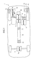
- FIG. 1 is a diagram showing an arrangement of a hybrid vehicle according to the present invention.
- FIG. 2 is a schematic diagram of an embodiment of a cooling apparatus for a vehicular engine according to the present invention.
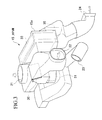
- FIG. 3 is a perspective view of an HPVM mounted in the hybrid vehicle.
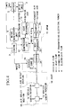
- FIG. 4 is a block diagram of the hybrid vehicle.
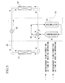
- FIG. 5 is a diagram showing a refrigerant path of an air conditioner mounted in the hybrid vehicle.
- FIG. 6 is a diagram showing the flow of coolant in the hybrid vehicle.
- the hybrid vehicle which uses both an electric motor and an engine as a drive source is one of the strong candidates for the alternative energy vehicle.
- the hybrid vehicle is driven by an engine at the time of high speed driving, and is driven by a drive motor with a battery as a power source at the time of low speed driving.
- the battery is charged by driving an electric power generation motor at the time of engine driving.
- numeral 1 denotes a hybrid vehicle, equipped with a drive unit 2 (apparatus to be cooled) in the front part of the vehicle having a motor 2a housed therein for driving front wheels, and an engine 3 (vehicle engine) in the rear part of the vehicle for driving rear wheels.
- a drive unit 2 apparatus to be cooled
- an engine 3 vehicle engine
- the engine 3 there is a diesel engine or a gasoline turbo charged engine.
- the hybrid vehicle 1 runs at the time of low speed driving, using the driving motor 2a as a drive source and runs at the time of high speed driving exceeding a certain speed, by switching the drive source to the engine 3.
- the engine 3 Since the motor 2a is provided in the front part of the vehicle, the engine 3 is arranged in the rear part of the vehicle, for the reason of mounting space and in consideration of air resistance. There is also the case where the engine 3 and the motor 2a are activated as the drive source at the same time.
- Numeral 5 denotes a battery (apparatus to be cooled) which is a power source for the motor 2a
- numeral 6 denotes a motor-generator unit (apparatus to be cooled) for converting the driving force of the engine 3 into electrical power and storing the electrical power in the battery 5.
- An electrical power generation motor (not shown) is mounted in the motor-generator unit 6, and electrical power is generated by transmitting the driving force of the engine 3 to the electrical power generation motor.
- the motor-generator unit 6 has the function of converting electrical power stored in the battery 5 into the driving force, by driving the electrical power generation motor with the electrical power.
- the battery 5 of this example is a high temperature battery which is stable in a high temperature range (for example 80°C ⁇ 90°C) with a high operating efficiency.
- a high temperature battery there is one which uses a halide of for example copper, nickel, or silver, for the positive electrode, and metallic lithium (alternatively an activated metal such as calcium, magnesium is also possible) for the negative electrode, and employs an organic substance such as propylene carbonate for the electrolyte.
- Numeral 50 denotes an I/C (intercooler) EGR system (apparatus to be cooled).
- This system 50 is provided with an EGR (Exhaust Gas Recirculation) unit 50a, and an intercooler 50b. That is to say, as shown in FIG. 2, the engine 3 is provided with an EGR (Exhaust Gas Recirculation) unit 50a for reintroducing a part of the exhaust gas back into the engine 3 to thereby reduce the NOx in the exhaust gas.
- an intercooler 50b is provided between the turbo charger 100 and the intake manifold 104 for reducing the intake temperature.
- the intercooler 50b of the turbo charger 100 and the EGR 50a are both liquid cooled types.
- numeral 8 denotes a first radiator for cooling the engine 3
- 9 denotes a second radiator provided together with the first radiator 8.
- the second radiator 9 is for cooling the driving motor 2a, the motor-generator unit 6 and the I/C EGR system 50.
- the first radiator 8 and second radiator 9 are so constructed that heat is discharged to the surrounding air by a fan 10 for the cooling radiators.
- a battery heat exchanger 11 (coolant heating device) for transferring heat from the engine 3 to the battery 5.
- the coolant outlet of the second radiator 9 and the coolant inlet of the intercooler 50b are connected by a coolant path 102 (pipe), and an electric pump 53 (intercooler coolant pump) is provided in the coolant path 102 for pumping the coolant.
- the coolant outlet of the intercooler 50b and the coolant inlet of the EGR 50a are connected by a coolant path 103 (pipe).
- the coolant outlet of the EGR 50a and the coolant inlet of the radiator 9 are connected by a coolant path 103 (pipe), thereby making up a coolant circulation circuit 105.
- the electric pump 53 When the automobile engine 3 is running (operating state), the electric pump 53 is also in the operating state so that coolant which has been cooled by the radiator 9 is circulated and sequentially supplied to the intercooler 50b and the EGR 50. Then when the automobile engine 3 is stopped, the operation of the electric pump 53 continues for a fixed period after stopping so that the circulation of the coolant which has been cooled by the second radiator 9 continues, to thereby cool the intercooler 50b and the EGR 50 and rapidly reduce the temperature thereof. The electric pump 53 is then stopped when a low temperature is reached.
- the electric pump 53 does not stop but continues to run for a fixed period so that immediately after stopping the engine the EGR and the intercooler which are conventionally at a high temperature are rapidly cooled so that the high temperature does not occur, thereby improving the life.
- the reason for having the flow sequence for the coolant in the order of intercooler 50b and EGR 50a is to effectively cool the intercooler 50b more than the EGR 50a.
- numeral 12 denotes a compressor unit for compressing a refrigerant
- 13 denotes a heat exchanger
- 14 denotes a fan for blowing air to the heat exchanger 13
- 15 denotes a module referred to as an HPVM (Heat Pump Ventilating Module).
- the heat exchanger 13 is provided on the right side of the vehicle body for facilitating heat exchange with outside air, and heat is forcibly exchanged with outside air by the fan 14.
- the HPVM 15 is arranged in the middle of the rear part of the vehicle body, and is connected to a duct 16 extending to the front of the vehicle body along a center of the lower part of the vehicle body. As shown in FIG. 3, the duct 16 is formed in a tubular shape, and is provided with air outlet sections 17 and 18 in the central portion and in the front end of the duct 16, respectively.
- HPVM 15 will now be described in detail.
- FIG. 3 shows a perspective view of the HPVM 15, and FIG. 4 shows a block diagram of the air conditioner.
- the HPVM 15 is constructed with a casing 15a, an inside air intake 21, an outside air intake 22, a discharge port 23 and a connecting portion 24 for connecting the HPVM to the duct 16.
- the inside air intake 21 is communicated with the vehicle cabin, and the outside air intake 22 and the discharge port 23 are communicated with outside of the vehicle cabin.
- the HPVM 15 is equipped with an inside air/outside air changeover damper 30 for determining which of either air inside of the vehicle cabin (inside air) or air outside of the vehicle cabin (outside air) is to be drawn in, a fan 31 for introducing air via the inside air/outside air changeover damper 30, a heat exchanger 33 for exchanging heat between the introduced air and the refrigerant, an air mix damper 34 for branching a part of the heat exchanged air, and a heater core 35 for heating the branched air.
- an inside air/outside air changeover damper 30 for determining which of either air inside of the vehicle cabin (inside air) or air outside of the vehicle cabin (outside air) is to be drawn in
- a fan 31 for introducing air via the inside air/outside air changeover damper 30, a heat exchanger 33 for exchanging heat between the introduced air and the refrigerant, an air mix damper 34 for branching a part of the heat exchanged air, and a heater core 35 for heating the branched air.
- the inside air/outside air changeover damper 30 By opening or closing the inside air/outside air changeover damper 30, it is possible to select either one of an inside air circulating operation for drawing in inside air from the inside air intake 21 (see FIG. 3) and sending the air to the duct 16, or an outside air introducing operation for introducing outside air from the outside air intake 22 (see FIG. 3) and sending the air to the duct 16, as well as discharging inside air from the discharge port 23 (see FIG. 3).
- the heater core 35 is a heat exchanger for receiving a supply of high temperature coolant from the engine 3, as described below, and heating a flow of introduced air. This is used supplementarily at the time of the heating operation (heat pump operation) of the air conditioner.
- the air mix damper 34 is for adjusting the quantity of introduced air branched off to the heater core 35, according to the opening thereof. The introduced air is then blown to the vehicle cabin from the air outlet sections 17 and 18 of the duct 16.
- the cooling operation or heating operation is effected by supplying refrigerant to the heat exchanger 33 and the heat exchanger 13 by the compressor unit 12.
- FIG. 5 shows the compressor unit 12.
- the compressor unit 12 includes, as main components, a compressor 41, a throttling resistance 42, a four way valve 43 and an accumulator 44.
- the above described heat exchangers 13 and 33 are connected between these respective devices by a refrigerant path 45 to form a refrigerant circuit.
- a driving force is transmitted to the compressor 41 by the engine 3 or the motor-generator unit 6.
- the compressor 41 has the function of compressing the refrigerant which has absorbed heat and been gasified in an evaporator, and discharging and sending the refrigerant as a high temperature and high pressure gas refrigerant to the four way valve 43.
- the throttling resistance 42 has the function of decompressing and expanding the high temperature and high pressure liquid refrigerant to give a low temperature and low pressure liquid refrigerant. This uses a capillary tube or an expansion valve.
- the accumulator 44 is provided for removing the liquid component contained in the gas refrigerant, so as to prevent a part of the liquid refrigerant which has not been evaporated completely by the evaporator from being drawn in directly to the compressor 41.
- the low temperature and low pressure liquid refrigerant is evaporated and gasified in the heat exchanger 33 (which operates as a condenser at the time of cooling) by absorbing heat from outside air, to become a low temperature and low pressure gas refrigerant, and is then sent to the compressor 41 and is compressed into a high temperature and high pressure gas refrigerant.
- the gas refrigerant releases heat to heat the air and is condensed and liquefied, after which it is expanded by passing through the throttling resistance 42 to become a low temperature and low pressure liquid refrigerant, and is circulated again to the heat exchanger 33.
- the heat exchanger 33 operates as an evaporator and cools the heating medium.
- the heat exchanger 13 functions as a condenser and heats the refrigerant.
- the high temperature and high pressure gas refrigerant supplied to the heat exchanger 33 is condensed and liquefied by discharging heat to the outside air. This is then expanded by the throttling resistance 42, and sent to the heat exchanger 13 to be evaporated and gasified, and is then sent to the compressor 41 and is again circulated to the heat exchanger 33.
- the heat exchanger 33 functions as a condenser and the heat exchanger 13 functions as an evaporator. That is to say, one of the heat exchangers of the cooling apparatus arranged in the air conditioner, by switching the four way valve, operates as an evaporator to demonstrate a cooling ability, and may also operate as a condenser to function as a heater.
- the temperature of the above described drive unit 2 and the motor-generator unit 6 is not higher than 65°C.
- the temperature of the battery 5 is ideally 85 ⁇ 5°C from the view point of storage efficiency.
- the temperature of the coolant is controlled as described below.
- FIG. 6 there are formed predetermined flow paths for flowing a coolant between the engine 3, the battery 5, the I/C EGR system 50, the drive unit 2, the motor-generator unit 6, the first radiator 8, the second radiator 9 and the battery heat exchanger 11.
- the engine 3 is cooled by the first radiator 8, and the battery 5, the I/C EGR system 50, the drive unit 2 and the motor-generator unit 6 are cooled by the second radiator 9.
- the I/C EGR system 50, the drive unit 2 and the motor-generator unit 6 are cooled by a coolant supplied from the second radiator 9.
- the coolant is supplied from the outlet side of the second radiator 9 to the flow path 51.
- the coolant is branched, at a branch point p1, to the I/C EGR system 50 side and the drive unit 2 and motor-generator unit 6 side.
- the coolant branched to the I/C EGR system 50 side is supplied into the I/C EGR system 50 via an inter-cooler coolant pump (electric pump) 53 interposed in a flow path b1.
- an inter-cooler coolant pump electric pump
- the coolant is again circulated to the second radiator 9 via a flow path 52.
- a flow velocity is given to the coolant by the inter-cooler coolant pump 53 to make the coolant flow in the flow path b1.
- the coolant branched to the drive unit 2 and the motor-generator unit 6 side is further branched at a branch point p2, after which a part of the coolant is further branched via a traction coolant pump (circulation quantity control device) 54.
- a traction coolant pump (circulation quantity control device) 54.
- One part is branched to a flow path b2 on the drive unit 2 side, and the other is branched to a flow path b3 on the motor-generator unit 6 side.
- the coolant after branching is supplied to the drive unit 2 and the motor-generator unit 6, respectively, similar to the coolant supplied to the I/C EGR system 50, for cooling the apparatus system, and is then again circulated to the second generator 9 via the flow path 52.
- a flow velocity is given to the coolant by the traction coolant pump 54 to make the coolant flow in the flow paths b2 and b3.
- the drive unit 2 is disposed in the front part of the vehicle body, as shown in FIG. 1.
- the motor-generator unit 6 and the second radiator 9 are disposed in the rear part of the vehicle body. That is, the flow path b2 is longer than the flow path b3, and has a larger coolant flow resistance. Therefore, when it is necessary to make the coolant flow to both the drive unit 2 and the motor-generator unit 6, the flow rate on the motor-generator unit 6 side becomes higher than that on the drive unit 2 side, resulting in uneven balance.
- a flow regulating valve 55 is interposed in the flow path b3 to maintain the flow rate balance with the flow path b2.
- the other coolant branched at the branch point p2 flows to the battery 5 side in a flow path b4 in which a battery coolant pump (circulation quantity control device) 57 is interposed.
- the high temperature coolant will be described later.
- the flow rate is adjusted beforehand so that after merging, the coolant attains a predetermined temperature (85 ⁇ 5°C).
- the coolant is supplied to the battery 5, and discharged to the outlet flow path b5, while maintaining the battery 5 within the above described predetermined temperature.
- the coolant is branched at a branch point p3 to flow paths b6 and b7.
- the construction is such that the flow path b6 passes through the battery heat exchanger 11 and joins the flow path b4 at the junction p4, and the flow path b7 joins the flow path 52 and is then circulated again to the second radiator 9.
- a flow regulating valve 60 is interposed in the flow path b6, and a flow regulating valve 61 is interposed in the flow path b7. The flow regulating valves will be described later.
- the coolant flowing in the flow path b6 is heated by the heat of the engine 3 in the battery heat exchanger 11.
- heat is exchanged between the flow path b6 and the flow path b10 which circulates the coolant between the engine 3 and the battery heat exchanger 11. Since the temperature of the coolant in the flow path b10 heated by the engine 3 is higher than that of the coolant in the flow path b6 (85 ⁇ 5°C), the coolant in the flow path b6 is heated to become a high temperature coolant, and merges with the low temperature coolant in the flow path b4 at the junction p4.
- the high temperature coolant and the low temperature coolant merge at the junction p4, to thereby supply the above described coolant having a predetermined temperature to the battery 5.
- the temperature of the coolant supplied to the battery 5 is controlled.
- Another flow path b11 to the engine 3 is provided independent of the above described flow path b10, to circulate the coolant between the first radiator 8 and the engine 3. Moreover, a flow path b12 is provided to circulate the coolant between the heater core 35 and the engine 3.
- the coolant discharged from the engine 3 is branched at a branch point p5 to flow paths b10, b11 and b12, and flows through the battery heat exchanger 11, the first radiator 8 and the heater core 35, respectively, after which it merges at the junction p6, and is then circulated again to the engine 3.
- An engine coolant pump 69 is provided in the flow path on the inlet side of the engine 3, to make the coolant flow in flow paths b10 ⁇ b12. Moreover, in the flow paths b10 and b12 there are provided flow regulating valves 71 and 73, respectively, and in the flow path b11 there is provided a thermostat 72.
- the first radiator 8 and the above described second radiator 9 are provided in parallel, and since the coolant flowing through the first radiator 8 has a higher temperature, a pull (suction) type radiator cooling fan 10 is arranged on the downstream side of the first radiator 8, so that air passing through the second radiator 9 passes through the first radiator 8.
- the hybrid vehicle 1 travels at the time of low speed driving, using the driving motor 2a as a drive source and travels at the time of high speed driving exceeding a certain speed, by switching the drive source to the engine 3.
- the drive source of the air conditioner is also different from that of the conventional vehicular air conditioner.
- the compressor unit 12 is driven by the driving force from the engine 3 at the time of air conditioning, to circulate the refrigerant between the heat exchangers 13 and 33.
- the engine 3 also transmits a driving force to the motor-generator unit 6, and the motor-generator unit 6 generates electrical power by a motor (not shown), and stores the electrical power in the battery 5.
- the fan 31 introduces inside air or outside air via the inside air/outside air changeover damper 30 to blow air to the heat exchanger 33.
- the heat of the introduced air is exchanged with the refrigerant in the heat exchanger 33, to thereby be heated (at the time of the heating operation), or cooled ( at the time of the cooling operation).
- the air, after being heated is directed to the duct 16 or the heater core 35 by means of the air mix damper 34, and the introduced air sent to the heater core 35 is further heated by the waste heat of the engine 3 and then sent to the duct 16.
- the motor-generator unit 6 drives the electrical power generating motor housed therein, using the electrical power stored in the battery 5.
- the driving force is transmitted to the compressor unit 12 to thereby circulate the refrigerant between the heat exchangers 13 and 33.
- Other operation is similar to that when the engine 3 is driving.
- the coolant discharged from the second radiator 9 is distributed via the flow path 51 to the various apparatus, branching at branch points p1 and p2. That is to say, the quantity of coolant circulated to the battery 5 is determined by the battery coolant pump 57, and the quantity of coolant circulated to the I/C EGR system 50 is determined by the intercooler coolant pump 53 (electric pump), and the quantity of coolant circulated to the drive unit 2 and the motor-generator unit 6 is determined by the traction coolant pump 54.
- the coolant is circulated using the engine coolant pump 69, between the engine 3 and the first radiator 8, to thereby cool the engine 3. Moreover, the coolant is also circulated in the I/C EGR system 50 using the intercooler coolant pump 53.
- the coolant is circulated. That is to say, in the case of storing electricity using the drive power of the engine 3, and in the case of operating the air conditioner when the engine 3 is stopped, the coolant is circulated to the motor-generator unit 6 using the traction coolant pump 54, to thereby cool the motor-generator unit 6.
- the coolant is circulated to the drive unit 2 using the traction coolant pump 54 to thereby cool the drive unit 2.
- the inter-cooler coolant pump 53 allows a reverse flow so that the coolant discharged from the drive unit 2 or the motor-generator unit 6 does not flow to the power element radiator 9 but flows to the I/C EGR system 50. There is thus the case where a route is traced circulating again to the traction coolant pump 54 via the branch point p1.
- the inter-cooler coolant pump 53 is operated even though cooling is not required for the I/C EGR system 50, to the extent that the abovementioned reverse flow does not occur.
- the traction coolant pump 54 is operated even in the case where cooling is not required for the drive unit 2 and the motor-generator unit 6, to the extent that reverse flow of coolant does not occur.
- the battery 5 is always maintained at a predetermined temperature irrespective of whether the engine 3 is driving or the motor 2a is driving.
- the battery coolant pump 57 is operated corresponding to a temperature change of the battery 5 so that high temperature coolant which has been adjusted in flow quantity by the flow control valves 60 and 61, and low temperature coolant are mixed at the junction point p4 to thereby maintain the temperature of the coolant circulated to the battery 5 continuously at a predetermined temperature.
- the example is given for a hybrid vehicle as the vehicle provided with the EGR and the intercooler.
- vehicle is not limited to this and may be a standard vehicle.
- the arrangement is not limited to the arrangement incorporating both the EGR and the intercooler cooled, but either one may be cooled by circulating the coolant with the electric pump.
- the operation of the electric pump after stopping continues on for a fixed period so that coolant cooled by the radiator is introduced to at least one of the EGR and the intercooler to provide cooling to thus rapidly reduce the temperature. Then when a low temperature is reached the electric pump is stopped. That is to say, even though the engine is stopped, the electric pump does not stop but continues to run for a fixed period so that immediately after stopping the engine at least one of the EGR and the intercooler which are conventionally at a high temperature are rapidly cooled so that the high temperature does not occur, thereby improving the life.
- the radiator, the electric pump, the intercooler and the exhaust gas recirculation unit are arranged in order in the coolant circulation circuit, and the coolant is supplied by the electric pump sequentially to the intercooler and the exhaust gas recirculation unit to thereby cool both the intercooler and the exhaust gas recirculation unit in order of the higher temperature.
Landscapes
- Engineering & Computer Science (AREA)
- Mechanical Engineering (AREA)
- Power Engineering (AREA)
- Transportation (AREA)
- Sustainable Development (AREA)
- General Engineering & Computer Science (AREA)
- Combustion & Propulsion (AREA)
- Life Sciences & Earth Sciences (AREA)
- Chemical & Material Sciences (AREA)
- Sustainable Energy (AREA)
- Physics & Mathematics (AREA)
- Thermal Sciences (AREA)
- Hybrid Electric Vehicles (AREA)
- Cooling, Air Intake And Gas Exhaust, And Fuel Tank Arrangements In Propulsion Units (AREA)
- Air-Conditioning For Vehicles (AREA)
- Exhaust-Gas Circulating Devices (AREA)
- Electric Propulsion And Braking For Vehicles (AREA)
Abstract
Description
- The present invention relates to a cooling apparatus for a vehicular engine, and in particular to cooling technology for an automobile engine which incorporates at least one of an exhaust gas recirculation unit and an intercooler.
- With an automobile engine, there are those where an EGR (Exhaust Gas Recirculation) unit is provided for reintroducing a part of the exhaust gas back into the engine to thereby reduce the NOx in the exhaust gas, and those where an intercooler is provided between the turbo charger and the intake manifold for cooling the intake and exhaust gas. Since the EGR and intercooler are each exposed to high temperature exhaust gas, a liquid cooling system is employed where a coolant is circulated by the engine pump, and the heat from the intercooler and the EGR is carried to the radiator, to thereby to cool the intercooler and the EGR.
- With the above, since the engine pump is used in the cooling of the EGR and the intercooler, when the engine stops, then the engine pump also inevitably stops. In this case, the temperature of the EGR and the intercooler increases, and hence immediately after stopping, the coolant therein boils and the metal parts are exposed to high temperature, with the result that there is a reduction in life.
- It is an object of the present invention to address the problems with the conventional technology, and provide a cooling apparatus for a vehicular engine which can improve the life of at least one of the exhaust gas recirculation unit and the intercooler.
- The cooling apparatus for a vehicular engine of the present invention for achieving the above object incorporates; a vehicular engine provided with at least one of an exhaust gas recirculation unit and a turbo charger intercooler, a radiator, and an electric pump for circulating coolant to carry heat generated by at least one of the intercooler and the exhaust gas recirculation unit to the radiator.
- With the present invention, when the vehicular engine is stopped, the operation of the electric pump after stopping continues on for a fixed period so that coolant cooled by the radiator is introduced to at least one of the EGR and the intercooler to provide cooling to thus rapidly reduce the temperature. Then when a low temperature is reached the electric pump is stopped.
- According to a second aspect of the present invention, the radiator, the electric pump, the intercooler and the exhaust gas recirculation unit are arranged in order in the coolant circulation circuit, and the coolant is supplied by the electric pump sequentially to the intercooler and the exhaust gas recirculation unit to thereby cool both the intercooler and the exhaust gas recirculation unit.
- FIG. 1 is a diagram showing an arrangement of a hybrid vehicle according to the present invention.
- FIG. 2 is a schematic diagram of an embodiment of a cooling apparatus for a vehicular engine according to the present invention.
- FIG. 3 is a perspective view of an HPVM mounted in the hybrid vehicle.
- FIG. 4 is a block diagram of the hybrid vehicle.
- FIG. 5 is a diagram showing a refrigerant path of an air conditioner mounted in the hybrid vehicle.
- FIG. 6 is a diagram showing the flow of coolant in the hybrid vehicle.
- Next is a description of an embodiment of an engine cooling apparatus, of the present invention using a hybrid vehicle as an example.
- At first is an outline of the hybrid vehicle. Recently, there has been an increasing demand for introducing a low-pollution vehicle and alternative energy vehicle, accompanied with demands for improving the air environment and environmental problems. The hybrid vehicle which uses both an electric motor and an engine as a drive source is one of the strong candidates for the alternative energy vehicle. The hybrid vehicle is driven by an engine at the time of high speed driving, and is driven by a drive motor with a battery as a power source at the time of low speed driving. The battery is charged by driving an electric power generation motor at the time of engine driving.
- As shown in FIG. 1,
numeral 1 denotes a hybrid vehicle, equipped with a drive unit 2 (apparatus to be cooled) in the front part of the vehicle having amotor 2a housed therein for driving front wheels, and an engine 3 (vehicle engine) in the rear part of the vehicle for driving rear wheels. As an example of theengine 3 there is a diesel engine or a gasoline turbo charged engine. However the engine is not limited to these and a naturally aspirated engine is also possible. Thehybrid vehicle 1 runs at the time of low speed driving, using thedriving motor 2a as a drive source and runs at the time of high speed driving exceeding a certain speed, by switching the drive source to theengine 3. Since themotor 2a is provided in the front part of the vehicle, theengine 3 is arranged in the rear part of the vehicle, for the reason of mounting space and in consideration of air resistance. There is also the case where theengine 3 and themotor 2a are activated as the drive source at the same time. - Numeral 5 denotes a battery (apparatus to be cooled) which is a power source for the
motor 2a, andnumeral 6 denotes a motor-generator unit (apparatus to be cooled) for converting the driving force of theengine 3 into electrical power and storing the electrical power in thebattery 5. An electrical power generation motor (not shown) is mounted in the motor-generator unit 6, and electrical power is generated by transmitting the driving force of theengine 3 to the electrical power generation motor. Moreover, the motor-generator unit 6 has the function of converting electrical power stored in thebattery 5 into the driving force, by driving the electrical power generation motor with the electrical power. Here thebattery 5 of this example is a high temperature battery which is stable in a high temperature range (for example 80°C ~ 90°C) with a high operating efficiency. As an example of a high temperature battery, there is one which uses a halide of for example copper, nickel, or silver, for the positive electrode, and metallic lithium (alternatively an activated metal such as calcium, magnesium is also possible) for the negative electrode, and employs an organic substance such as propylene carbonate for the electrolyte. - Numeral 50 denotes an I/C (intercooler) EGR system (apparatus to be cooled). This
system 50 is provided with an EGR (Exhaust Gas Recirculation)unit 50a, and anintercooler 50b. That is to say, as shown in FIG. 2, theengine 3 is provided with an EGR (Exhaust Gas Recirculation)unit 50a for reintroducing a part of the exhaust gas back into theengine 3 to thereby reduce the NOx in the exhaust gas. In addition anintercooler 50b is provided between theturbo charger 100 and theintake manifold 104 for reducing the intake temperature. Here theintercooler 50b of theturbo charger 100 and the EGR 50a are both liquid cooled types. - Again, as shown in FIG. 1,
numeral 8 denotes a first radiator for cooling theengine first radiator 8. Thesecond radiator 9 is for cooling thedriving motor 2a, the motor-generator unit 6 and the I/C EGR system 50. Thefirst radiator 8 andsecond radiator 9 are so constructed that heat is discharged to the surrounding air by afan 10 for the cooling radiators. Moreover, there is provided a battery heat exchanger 11 (coolant heating device) for transferring heat from theengine 3 to thebattery 5. - Here the characteristic parts of the embodiment will be described. As shown in FIG. 2, the coolant outlet of the
second radiator 9 and the coolant inlet of theintercooler 50b are connected by a coolant path 102 (pipe), and an electric pump 53 (intercooler coolant pump) is provided in thecoolant path 102 for pumping the coolant. The coolant outlet of theintercooler 50b and the coolant inlet of the EGR 50a are connected by a coolant path 103 (pipe). Moreover, the coolant outlet of the EGR 50a and the coolant inlet of theradiator 9 are connected by a coolant path 103 (pipe), thereby making up acoolant circulation circuit 105. - When the
automobile engine 3 is running (operating state), theelectric pump 53 is also in the operating state so that coolant which has been cooled by theradiator 9 is circulated and sequentially supplied to theintercooler 50b and the EGR 50. Then when theautomobile engine 3 is stopped, the operation of theelectric pump 53 continues for a fixed period after stopping so that the circulation of the coolant which has been cooled by thesecond radiator 9 continues, to thereby cool theintercooler 50b and the EGR 50 and rapidly reduce the temperature thereof. Theelectric pump 53 is then stopped when a low temperature is reached. That is to say, even though theautomobile engine 3 is stopped, theelectric pump 53 does not stop but continues to run for a fixed period so that immediately after stopping the engine the EGR and the intercooler which are conventionally at a high temperature are rapidly cooled so that the high temperature does not occur, thereby improving the life. The reason for having the flow sequence for the coolant in the order ofintercooler 50b and EGR 50a is to effectively cool theintercooler 50b more than the EGR 50a. - Next is a description of an air conditioning apparatus (referred to hereunder as an air conditioner) mounted in the
hybrid vehicle 1. - In FIG. 1,
numeral 12 denotes a compressor unit for compressing a refrigerant, 13 denotes a heat exchanger, 14 denotes a fan for blowing air to theheat exchanger heat exchanger 13 is provided on the right side of the vehicle body for facilitating heat exchange with outside air, and heat is forcibly exchanged with outside air by thefan 14. The HPVM 15 is arranged in the middle of the rear part of the vehicle body, and is connected to aduct 16 extending to the front of the vehicle body along a center of the lower part of the vehicle body. As shown in FIG. 3, theduct 16 is formed in a tubular shape, and is provided withair outlet sections duct 16, respectively. - The HPVM 15 will now be described in detail.
- FIG. 3 shows a perspective view of the
HPVM 15, and FIG. 4 shows a block diagram of the air conditioner. - In FIG. 3, the
HPVM 15 is constructed with acasing 15a, aninside air intake 21, anoutside air intake 22, adischarge port 23 and a connectingportion 24 for connecting the HPVM to theduct 16. - The
inside air intake 21 is communicated with the vehicle cabin, and theoutside air intake 22 and thedischarge port 23 are communicated with outside of the vehicle cabin. - Moreover, as shown in FIG. 4, the
HPVM 15 is equipped with an inside air/outsideair changeover damper 30 for determining which of either air inside of the vehicle cabin (inside air) or air outside of the vehicle cabin (outside air) is to be drawn in, afan 31 for introducing air via the inside air/outsideair changeover damper 30, aheat exchanger 33 for exchanging heat between the introduced air and the refrigerant, anair mix damper 34 for branching a part of the heat exchanged air, and aheater core 35 for heating the branched air. - By opening or closing the inside air/outside
air changeover damper 30, it is possible to select either one of an inside air circulating operation for drawing in inside air from the inside air intake 21 (see FIG. 3) and sending the air to theduct 16, or an outside air introducing operation for introducing outside air from the outside air intake 22 (see FIG. 3) and sending the air to theduct 16, as well as discharging inside air from the discharge port 23 (see FIG. 3). - The
heater core 35 is a heat exchanger for receiving a supply of high temperature coolant from theengine 3, as described below, and heating a flow of introduced air. This is used supplementarily at the time of the heating operation (heat pump operation) of the air conditioner. Theair mix damper 34 is for adjusting the quantity of introduced air branched off to theheater core 35, according to the opening thereof. The introduced air is then blown to the vehicle cabin from theair outlet sections duct 16. - The cooling operation or heating operation is effected by supplying refrigerant to the
heat exchanger 33 and theheat exchanger 13 by thecompressor unit 12. FIG. 5 shows thecompressor unit 12. - As shown in FIG. 5, the
compressor unit 12 includes, as main components, acompressor 41, a throttlingresistance 42, a fourway valve 43 and anaccumulator 44. The above describedheat exchangers refrigerant path 45 to form a refrigerant circuit. - A driving force is transmitted to the
compressor 41 by theengine 3 or the motor-generator unit 6. Thecompressor 41 has the function of compressing the refrigerant which has absorbed heat and been gasified in an evaporator, and discharging and sending the refrigerant as a high temperature and high pressure gas refrigerant to the fourway valve 43. By switching the fourway valve 43, the flow direction of the high temperature and high pressure gas refrigerant discharged from thecompressor 41 is changed, resulting in changeover of the cooling or heating operation. Moreover, the throttlingresistance 42 has the function of decompressing and expanding the high temperature and high pressure liquid refrigerant to give a low temperature and low pressure liquid refrigerant. This uses a capillary tube or an expansion valve. Theaccumulator 44 is provided for removing the liquid component contained in the gas refrigerant, so as to prevent a part of the liquid refrigerant which has not been evaporated completely by the evaporator from being drawn in directly to thecompressor 41. - With the above described refrigerant circuit, at the time of the heating operation, the low temperature and low pressure liquid refrigerant is evaporated and gasified in the heat exchanger 33 (which operates as a condenser at the time of cooling) by absorbing heat from outside air, to become a low temperature and low pressure gas refrigerant, and is then sent to the
compressor 41 and is compressed into a high temperature and high pressure gas refrigerant. Thereafter, in the heat exchanger 13 (which operates as an evaporator at the time of cooling) the gas refrigerant releases heat to heat the air and is condensed and liquefied, after which it is expanded by passing through the throttlingresistance 42 to become a low temperature and low pressure liquid refrigerant, and is circulated again to theheat exchanger 33. In this case, theheat exchanger 33 operates as an evaporator and cools the heating medium. Moreover, theheat exchanger 13 functions as a condenser and heats the refrigerant. - At the time of the cooling operation, the high temperature and high pressure gas refrigerant supplied to the
heat exchanger 33 is condensed and liquefied by discharging heat to the outside air. This is then expanded by the throttlingresistance 42, and sent to theheat exchanger 13 to be evaporated and gasified, and is then sent to thecompressor 41 and is again circulated to theheat exchanger 33. In this case, theheat exchanger 33 functions as a condenser and theheat exchanger 13 functions as an evaporator. That is to say, one of the heat exchangers of the cooling apparatus arranged in the air conditioner, by switching the four way valve, operates as an evaporator to demonstrate a cooling ability, and may also operate as a condenser to function as a heater. When operated as an evaporator, cooling, dehumidifying and temperature adjustment is possible, while when operated as a heater, this can act in place of the heater core. Therefore, even when the engine cooling water temperature is low so that there is no heating effect, heating ability can be demonstrated. Moreover, this supplementary heating operation immediately after starting the engine operation naturally has a sufficient heating ability for when driving under electrical power, without using the engine. - With the above construction, for safe operation it is required that the temperature of the above described
drive unit 2 and the motor-generator unit 6 is not higher than 65°C. Moreover, the temperature of thebattery 5 is ideally 85 ± 5°C from the view point of storage efficiency. To satisfy this requirement, in thehybrid vehicle 1, the temperature of the coolant is controlled as described below. - As shown in FIG. 6, there are formed predetermined flow paths for flowing a coolant between the
engine 3, thebattery 5, the I/C EGR system 50, thedrive unit 2, the motor-generator unit 6, thefirst radiator 8, thesecond radiator 9 and thebattery heat exchanger 11. - The
engine 3 is cooled by thefirst radiator 8, and thebattery 5, the I/C EGR system 50, thedrive unit 2 and the motor-generator unit 6 are cooled by thesecond radiator 9. - Next is a detailed description of the flow path.
- The I/
C EGR system 50, thedrive unit 2 and the motor-generator unit 6 are cooled by a coolant supplied from thesecond radiator 9. - First, the coolant is supplied from the outlet side of the
second radiator 9 to theflow path 51. The coolant is branched, at a branch point p1, to the I/C EGR system 50 side and thedrive unit 2 and motor-generator unit 6 side. - The coolant branched to the I/
C EGR system 50 side is supplied into the I/C EGR system 50 via an inter-cooler coolant pump (electric pump) 53 interposed in a flow path b1. After cooling the apparatus system in the I/C EGR system 50, the coolant is again circulated to thesecond radiator 9 via aflow path 52. At this time, a flow velocity is given to the coolant by theinter-cooler coolant pump 53 to make the coolant flow in the flow path b1. - On the other hand, the coolant branched to the
drive unit 2 and the motor-generator unit 6 side is further branched at a branch point p2, after which a part of the coolant is further branched via a traction coolant pump (circulation quantity control device) 54. One part is branched to a flow path b2 on thedrive unit 2 side, and the other is branched to a flow path b3 on the motor-generator unit 6 side. The coolant after branching is supplied to thedrive unit 2 and the motor-generator unit 6, respectively, similar to the coolant supplied to the I/C EGR system 50, for cooling the apparatus system, and is then again circulated to thesecond generator 9 via theflow path 52. At this time, a flow velocity is given to the coolant by thetraction coolant pump 54 to make the coolant flow in the flow paths b2 and b3. - Here, the
drive unit 2 is disposed in the front part of the vehicle body, as shown in FIG. 1. On the other hand, the motor-generator unit 6 and thesecond radiator 9 are disposed in the rear part of the vehicle body. That is, the flow path b2 is longer than the flow path b3, and has a larger coolant flow resistance. Therefore, when it is necessary to make the coolant flow to both thedrive unit 2 and the motor-generator unit 6, the flow rate on the motor-generator unit 6 side becomes higher than that on thedrive unit 2 side, resulting in uneven balance. To solve this problem, aflow regulating valve 55 is interposed in the flow path b3 to maintain the flow rate balance with the flow path b2. - The other coolant branched at the branch point p2 flows to the
battery 5 side in a flow path b4 in which a battery coolant pump (circulation quantity control device) 57 is interposed. - At a junction p4 before the
battery coolant pump 57, this merges with a high temperature coolant heated by the heat of theengine 3. The high temperature coolant will be described later. The flow rate is adjusted beforehand so that after merging, the coolant attains a predetermined temperature (85 ± 5°C). - Thereafter, the coolant is supplied to the
battery 5, and discharged to the outlet flow path b5, while maintaining thebattery 5 within the above described predetermined temperature. The coolant is branched at a branch point p3 to flow paths b6 and b7. The construction is such that the flow path b6 passes through thebattery heat exchanger 11 and joins the flow path b4 at the junction p4, and the flow path b7 joins theflow path 52 and is then circulated again to thesecond radiator 9. Aflow regulating valve 60 is interposed in the flow path b6, and aflow regulating valve 61 is interposed in the flow path b7. The flow regulating valves will be described later. - The coolant flowing in the flow path b6 is heated by the heat of the
engine 3 in thebattery heat exchanger 11. In more detail, in thebattery heat exchanger 11, heat is exchanged between the flow path b6 and the flow path b10 which circulates the coolant between theengine 3 and thebattery heat exchanger 11. Since the temperature of the coolant in the flow path b10 heated by theengine 3 is higher than that of the coolant in the flow path b6 (85 ± 5°C), the coolant in the flow path b6 is heated to become a high temperature coolant, and merges with the low temperature coolant in the flow path b4 at the junction p4. - In this way, the high temperature coolant and the low temperature coolant merge at the junction p4, to thereby supply the above described coolant having a predetermined temperature to the
battery 5. By adjusting the quantity of the high temperature coolant by the above describedflow regulating valves battery 5 is controlled. - Another flow path b11 to the
engine 3 is provided independent of the above described flow path b10, to circulate the coolant between thefirst radiator 8 and theengine 3. Moreover, a flow path b12 is provided to circulate the coolant between theheater core 35 and theengine 3. - The coolant discharged from the
engine 3 is branched at a branch point p5 to flow paths b10, b11 and b12, and flows through thebattery heat exchanger 11, thefirst radiator 8 and theheater core 35, respectively, after which it merges at the junction p6, and is then circulated again to theengine 3. - An
engine coolant pump 69 is provided in the flow path on the inlet side of theengine 3, to make the coolant flow in flow paths b10 ~ b12. Moreover, in the flow paths b10 and b12 there are providedflow regulating valves thermostat 72. - The
first radiator 8 and the above describedsecond radiator 9 are provided in parallel, and since the coolant flowing through thefirst radiator 8 has a higher temperature, a pull (suction) typeradiator cooling fan 10 is arranged on the downstream side of thefirst radiator 8, so that air passing through thesecond radiator 9 passes through thefirst radiator 8. - Next is a description of the operation of the above described air conditioner.
- As described above, the
hybrid vehicle 1 travels at the time of low speed driving, using the drivingmotor 2a as a drive source and travels at the time of high speed driving exceeding a certain speed, by switching the drive source to theengine 3. Hence, the drive source of the air conditioner is also different from that of the conventional vehicular air conditioner. - First, when the
hybrid vehicle 1 travels using theengine 3, thecompressor unit 12 is driven by the driving force from theengine 3 at the time of air conditioning, to circulate the refrigerant between theheat exchangers engine 3 also transmits a driving force to the motor-generator unit 6, and the motor-generator unit 6 generates electrical power by a motor (not shown), and stores the electrical power in thebattery 5. - With the
HPVM 15, thefan 31 introduces inside air or outside air via the inside air/outsideair changeover damper 30 to blow air to theheat exchanger 33. The heat of the introduced air is exchanged with the refrigerant in theheat exchanger 33, to thereby be heated (at the time of the heating operation), or cooled ( at the time of the cooling operation). - The air, after being heated is directed to the
duct 16 or theheater core 35 by means of theair mix damper 34, and the introduced air sent to theheater core 35 is further heated by the waste heat of theengine 3 and then sent to theduct 16. - On the other hand, when the
motor 2a is driving and theengine 3 is stopped, operation is as follows. That is, the motor-generator unit 6 drives the electrical power generating motor housed therein, using the electrical power stored in thebattery 5. The driving force is transmitted to thecompressor unit 12 to thereby circulate the refrigerant between theheat exchangers engine 3 is driving. - Next is a description of the coolant circulation. As shown in FIG. 6, the coolant discharged from the
second radiator 9 is distributed via theflow path 51 to the various apparatus, branching at branch points p1 and p2. That is to say, the quantity of coolant circulated to thebattery 5 is determined by thebattery coolant pump 57, and the quantity of coolant circulated to the I/C EGR system 50 is determined by the intercooler coolant pump 53 (electric pump), and the quantity of coolant circulated to thedrive unit 2 and the motor-generator unit 6 is determined by thetraction coolant pump 54. - Next is a separate description of the coolant circulation for when the
engine 3 is driving, and for when themotor 2a is driving. - When travelling using the
engine 3, then as with the conventional engine vehicle, the coolant is circulated using theengine coolant pump 69, between theengine 3 and thefirst radiator 8, to thereby cool theengine 3. Moreover, the coolant is also circulated in the I/C EGR system 50 using theintercooler coolant pump 53. - With the motor-
generator unit 6, when the electric power generating motor housed therein is driven, the coolant is circulated. That is to say, in the case of storing electricity using the drive power of theengine 3, and in the case of operating the air conditioner when theengine 3 is stopped, the coolant is circulated to the motor-generator unit 6 using thetraction coolant pump 54, to thereby cool the motor-generator unit 6. - On the other hand, when travelling by means of the
motor 2a, the coolant is circulated to thedrive unit 2 using thetraction coolant pump 54 to thereby cool thedrive unit 2. - Here, it is not necessary to cool the I/
C EGR system 50 when theengine 3 is stopped. Consequently, it is not necessary to operate theinter-cooler coolant pump 53. Hence there is the case where when this pump is fully stopped, the coolant is made to flow back by the drive of another pump. For example, in the case where theinter-cooler coolant pump 53 is stopped and thetraction coolant pump 54 is operating, theinter-cooler coolant pump 53 allows a reverse flow so that the coolant discharged from thedrive unit 2 or the motor-generator unit 6 does not flow to thepower element radiator 9 but flows to the I/C EGR system 50. There is thus the case where a route is traced circulating again to thetraction coolant pump 54 via the branch point p1. - In order to prevent this, the
inter-cooler coolant pump 53 is operated even though cooling is not required for the I/C EGR system 50, to the extent that the abovementioned reverse flow does not occur. - That is to say, even though the engine is stopped, the electric pump does not stop but continues to run for a fixed period. As a result, immediately after stopping, the intercooler and the EGR which are conventionally at a high temperature are rapidly cooled due to this operation so that the high temperature does not occur, thereby improving the life.
- Similarly, the
traction coolant pump 54 is operated even in the case where cooling is not required for thedrive unit 2 and the motor-generator unit 6, to the extent that reverse flow of coolant does not occur. - Moreover, the
battery 5 is always maintained at a predetermined temperature irrespective of whether theengine 3 is driving or themotor 2a is driving. Thebattery coolant pump 57 is operated corresponding to a temperature change of thebattery 5 so that high temperature coolant which has been adjusted in flow quantity by theflow control valves battery 5 continuously at a predetermined temperature. - Here with the abovementioned embodiment, the example is given for a hybrid vehicle as the vehicle provided with the EGR and the intercooler. However the vehicle is not limited to this and may be a standard vehicle. Moreover, the arrangement is not limited to the arrangement incorporating both the EGR and the intercooler cooled, but either one may be cooled by circulating the coolant with the electric pump.
- With the present invention, since this is constructed as described above, then when the vehicular engine is stopped, the operation of the electric pump after stopping continues on for a fixed period so that coolant cooled by the radiator is introduced to at least one of the EGR and the intercooler to provide cooling to thus rapidly reduce the temperature. Then when a low temperature is reached the electric pump is stopped. That is to say, even though the engine is stopped, the electric pump does not stop but continues to run for a fixed period so that immediately after stopping the engine at least one of the EGR and the intercooler which are conventionally at a high temperature are rapidly cooled so that the high temperature does not occur, thereby improving the life.
- According to the second aspect of the present invention, the radiator, the electric pump, the intercooler and the exhaust gas recirculation unit are arranged in order in the coolant circulation circuit, and the coolant is supplied by the electric pump sequentially to the intercooler and the exhaust gas recirculation unit to thereby cool both the intercooler and the exhaust gas recirculation unit in order of the higher temperature.
Claims (2)
- A cooling apparatus for a vehicular engine incorporating: a vehicular engine provided with at least one of an exhaust gas recirculation unit and a turbo charger intercooler; a radiator; and an electric pump for circulating coolant to carry heat generated by at least one of said intercooler and said exhaust gas recirculation unit to said radiator.
- A cooling apparatus for a vehicular engine according to claim 1, wherein said radiator, said electric pump, said intercooler and said exhaust gas recirculation unit are arranged in order in said coolant circulation circuit, and said coolant is supplied by said electric pump sequentially to said intercooler and said exhaust gas recirculation unit.
Applications Claiming Priority (2)
| Application Number | Priority Date | Filing Date | Title |
|---|---|---|---|
| US09/326,610 US6321697B1 (en) | 1999-06-07 | 1999-06-07 | Cooling apparatus for vehicular engine |
| US326610 | 1999-06-07 |
Publications (3)
| Publication Number | Publication Date |
|---|---|
| EP1059432A2 true EP1059432A2 (en) | 2000-12-13 |
| EP1059432A3 EP1059432A3 (en) | 2001-07-11 |
| EP1059432B1 EP1059432B1 (en) | 2003-11-19 |
Family
ID=23272949
Family Applications (1)
| Application Number | Title | Priority Date | Filing Date |
|---|---|---|---|
| EP00401583A Expired - Lifetime EP1059432B1 (en) | 1999-06-07 | 2000-06-06 | Cooling apparatus for vehicular engine |
Country Status (6)
| Country | Link |
|---|---|
| US (1) | US6321697B1 (en) |
| EP (1) | EP1059432B1 (en) |
| JP (1) | JP2001003747A (en) |
| KR (1) | KR100359700B1 (en) |
| CN (1) | CN1162609C (en) |
| DE (1) | DE60006612T2 (en) |
Cited By (8)
| Publication number | Priority date | Publication date | Assignee | Title |
|---|---|---|---|---|
| WO2005073535A1 (en) * | 2004-02-01 | 2005-08-11 | Behr Gmbh & Co. Kg | Arrangement for cooling exhaust gas and charge air |
| FR2872545A1 (en) * | 2004-07-05 | 2006-01-06 | Peugeot Citroen Automobiles Sa | THERMAL CONTROL DEVICE OF AN INTERNAL COMBUSTION ENGINE |
| FR2911092A1 (en) * | 2007-01-08 | 2008-07-11 | Peugeot Citroen Automobiles Sa | MULTIFUNCTION THERMAL MANAGEMENT SYSTEM AND METHOD FOR HYBRID VEHICLE |
| FR2951114A1 (en) * | 2009-10-13 | 2011-04-15 | Peugeot Citroen Automobiles Sa | COOLING DEVICE FOR A HYBRID VEHICLE |
| WO2011050892A1 (en) * | 2009-10-30 | 2011-05-05 | Bayerische Motoren Werke Aktiengesellschaft | Drive for a hybrid vehicle |
| GB2509737A (en) * | 2013-01-11 | 2014-07-16 | Gm Global Tech Operations Inc | Exhaust gas recirculation (EGR) system with active control of EGR coolant temperature |
| EP3470646A1 (en) * | 2017-10-10 | 2019-04-17 | Volkswagen Aktiengesellschaft | Combustion engine, motor vehicle and method for operating a combustion engine |
| WO2019185663A1 (en) * | 2018-03-27 | 2019-10-03 | Renault S.A.S | Cooling circuit for an internal combustion engine provided with an exhaust gas recirculation circuit and control method therefor |
Families Citing this family (69)
| Publication number | Priority date | Publication date | Assignee | Title |
|---|---|---|---|---|
| JP3867521B2 (en) * | 2000-09-05 | 2007-01-10 | トヨタ自動車株式会社 | Electric oil pump control device |
| US6450275B1 (en) * | 2000-11-02 | 2002-09-17 | Ford Motor Company | Power electronics cooling for a hybrid electric vehicle |
| US20060086546A1 (en) * | 2002-02-08 | 2006-04-27 | Green Vision Technology, Llc | Internal combustion engines for hybrid power train |
| JP3972863B2 (en) * | 2003-05-26 | 2007-09-05 | 株式会社デンソー | Vehicle cooling system |
| US7469741B2 (en) * | 2004-04-26 | 2008-12-30 | Mahle International Gmbh | Non-metallic laser welded intercooler system |
| US20050241308A1 (en) * | 2004-04-30 | 2005-11-03 | Iqbal Muhammad H | Integral radiator and charge air cooler |
| KR20070102574A (en) * | 2005-01-28 | 2007-10-18 | 타이탄 리서치 앤드 이노베이션스 피티와이 리미티드 | Engine aftercooling system |
| US7454896B2 (en) * | 2005-02-23 | 2008-11-25 | Emp Advanced Development, Llc | Thermal management system for a vehicle |
| US7267086B2 (en) * | 2005-02-23 | 2007-09-11 | Emp Advanced Development, Llc | Thermal management system and method for a heat producing system |
| SE528621C2 (en) * | 2005-05-18 | 2006-12-27 | Scania Cv Ab | Arrangements for the recirculation of exhaust gases of a supercharged internal combustion engine |
| SE528620C2 (en) * | 2005-05-18 | 2006-12-27 | Scania Cv Ab | Arrangements for the recirculation of exhaust gases of a supercharged internal combustion engine |
| US7455745B2 (en) * | 2005-06-03 | 2008-11-25 | Mahle International Gmbh | Laser welding of a plastic manifold |
| US7254947B2 (en) * | 2005-06-10 | 2007-08-14 | Deere & Company | Vehicle cooling system |
| DE102005047653B4 (en) * | 2005-10-05 | 2021-08-19 | Volkswagen Ag | Hybrid drive unit with low temperature circuit |
| US7669417B2 (en) | 2006-01-30 | 2010-03-02 | Titan Research And Innovations Pty Ltd | Engine after-cooling system |
| US7261068B1 (en) * | 2006-02-16 | 2007-08-28 | Deere & Company | Vehicular thermostatically-controlled dual-circuit cooling system and associated method |
| SE530239C2 (en) * | 2006-10-03 | 2008-04-08 | Scania Cv Ab | Radiator arrangement of a vehicle |
| US20090078220A1 (en) * | 2007-09-25 | 2009-03-26 | Ford Global Technologies, Llc | Cooling System with Isolated Cooling Circuits |
| JP2011508851A (en) * | 2008-01-03 | 2011-03-17 | マック トラックス インコーポレイテッド | Exhaust gas recirculation cooling circuit |
| US7866157B2 (en) * | 2008-05-12 | 2011-01-11 | Cummins Inc. | Waste heat recovery system with constant power output |
| SE533942C2 (en) * | 2008-06-09 | 2011-03-08 | Scania Cv Ab | Arrangement of a supercharged internal combustion engine |
| US20100218916A1 (en) * | 2009-02-27 | 2010-09-02 | Ford Global Technolgies, Llc | Plug-in hybrid electric vehicle secondary cooling system |
| US20100230189A1 (en) * | 2009-03-13 | 2010-09-16 | Gm Global Technology Operrations, Inc. | Cooling system for a vehicle |
| CN102395767B (en) * | 2009-04-16 | 2014-03-26 | 丰田自动车株式会社 | Control device for internal combustion engine |
| US8544274B2 (en) * | 2009-07-23 | 2013-10-01 | Cummins Intellectual Properties, Inc. | Energy recovery system using an organic rankine cycle |
| US8627663B2 (en) * | 2009-09-02 | 2014-01-14 | Cummins Intellectual Properties, Inc. | Energy recovery system and method using an organic rankine cycle with condenser pressure regulation |
| US8387572B2 (en) * | 2009-12-04 | 2013-03-05 | Ford Global Technologies, Llc | Auxiliary pump scheme for a cooling system in a hybrid-electric vehicle |
| DE102009054873A1 (en) * | 2009-12-17 | 2011-06-22 | ZF Friedrichshafen AG, 88046 | motor vehicle |
| US20110206951A1 (en) * | 2010-02-25 | 2011-08-25 | Peter Ford | Hybrid vehicle battery heater by exhaust gas recirculation |
| CN103237961B (en) | 2010-08-05 | 2015-11-25 | 康明斯知识产权公司 | Adopt the critical supercharging cooling of the discharge of organic Rankine bottoming cycle |
| CN103180553B (en) | 2010-08-09 | 2015-11-25 | 康明斯知识产权公司 | Comprise Waste Heat Recovery System (WHRS) and the internal-combustion engine system of rankine cycle RC subtense angle |
| WO2012021757A2 (en) | 2010-08-11 | 2012-02-16 | Cummins Intellectual Property, Inc. | Split radiator design for heat rejection optimization for a waste heat recovery system |
| CN103180554B (en) | 2010-08-13 | 2016-01-20 | 康明斯知识产权公司 | Rankine Cycle Condenser Pressure Control Using Transducer Bypass Valve |
| US8826662B2 (en) | 2010-12-23 | 2014-09-09 | Cummins Intellectual Property, Inc. | Rankine cycle system and method |
| DE112011104516B4 (en) | 2010-12-23 | 2017-01-19 | Cummins Intellectual Property, Inc. | System and method for regulating EGR cooling using a Rankine cycle |
| DE102012000100A1 (en) | 2011-01-06 | 2012-07-12 | Cummins Intellectual Property, Inc. | Rankine cycle-HEAT USE SYSTEM |
| WO2012096958A1 (en) | 2011-01-10 | 2012-07-19 | Cummins Intellectual Property, Inc. | Rankine cycle waste heat recovery system |
| JP2012149575A (en) * | 2011-01-19 | 2012-08-09 | Toyota Motor Corp | Cooling apparatus of internal combustion engine |
| US8919328B2 (en) | 2011-01-20 | 2014-12-30 | Cummins Intellectual Property, Inc. | Rankine cycle waste heat recovery system and method with improved EGR temperature control |
| JP2012154092A (en) * | 2011-01-26 | 2012-08-16 | Kobelco Contstruction Machinery Ltd | Hybrid construction machine |
| WO2012150994A1 (en) | 2011-02-28 | 2012-11-08 | Cummins Intellectual Property, Inc. | Engine having integrated waste heat recovery |
| JP2013256936A (en) * | 2012-05-16 | 2013-12-26 | Denso Corp | Exhaust recirculating device |
| DE102012210320B3 (en) * | 2012-06-19 | 2013-09-26 | Ford Global Technologies, Llc | Liquid-cooled combustion engine for vehicle, has steering valve arranged in connecting line between pump and vent tank and providing enlarged passage area as result of reduced pressure refrigerant in work position |
| US8893495B2 (en) | 2012-07-16 | 2014-11-25 | Cummins Intellectual Property, Inc. | Reversible waste heat recovery system and method |
| US9140209B2 (en) | 2012-11-16 | 2015-09-22 | Cummins Inc. | Rankine cycle waste heat recovery system |
| DE102013002198A1 (en) * | 2013-02-07 | 2014-08-07 | Man Truck & Bus Ag | Method and arrangement for optimizing the motor availability of a refrigerated cycle cooled electromobility component |
| WO2014125570A1 (en) * | 2013-02-12 | 2014-08-21 | トヨタ自動車株式会社 | Control device for internal combustion engine |
| JP6024822B2 (en) | 2013-04-30 | 2016-11-16 | トヨタ自動車株式会社 | Cooling water control device |
| EP2993325B1 (en) * | 2013-04-30 | 2018-05-23 | Toyota Jidosha Kabushiki Kaisha | Cooling water control apparatus |
| US9845711B2 (en) | 2013-05-24 | 2017-12-19 | Cummins Inc. | Waste heat recovery system |
| KR101534744B1 (en) * | 2013-12-16 | 2015-07-24 | 현대자동차 주식회사 | Cooling system for diesel engine having turbo charger |
| US9751381B2 (en) | 2014-01-24 | 2017-09-05 | Ford Global Technologies, Llc | Method and system for vehicle climate control |
| JP5904227B2 (en) * | 2014-03-24 | 2016-04-13 | トヨタ自動車株式会社 | Engine cooling system |
| KR101566746B1 (en) * | 2014-10-31 | 2015-11-06 | 현대자동차 주식회사 | Cooling system for vehicle |
| JP6072752B2 (en) * | 2014-11-12 | 2017-02-01 | 本田技研工業株式会社 | Cooling control device for internal combustion engine |
| DE102015215164A1 (en) * | 2015-08-07 | 2017-02-09 | Continental Automotive Gmbh | Thermal management system for a motor vehicle and method for operating a thermal management system for a motor vehicle |
| US10196960B2 (en) * | 2017-03-09 | 2019-02-05 | GM Global Technology Operations LLC | Cooling system having variable coolant flow paths for exhaust gas recirculation system |
| US10557406B2 (en) * | 2017-05-15 | 2020-02-11 | GM Global Technology Operations LLC | System and method for regulating coolant flow through a charge air cooler of a vehicle |
| US12049899B2 (en) | 2017-08-28 | 2024-07-30 | Mark J. Maynard | Systems and methods for improving the performance of air-driven generators using solar thermal heating |
| US12270404B2 (en) | 2017-08-28 | 2025-04-08 | Mark J. Maynard | Gas-driven generator system comprising an elongate gravitational distribution conduit coupled with a gas injection system |
| JP6848827B2 (en) * | 2017-11-24 | 2021-03-24 | トヨタ自動車株式会社 | Internal combustion engine control device |
| AU2019209876A1 (en) * | 2018-01-18 | 2020-08-13 | Mark J. Maynard | Gaseous fluid compression with alternating refrigeration and mechanical compression |
| KR20200040996A (en) * | 2018-10-11 | 2020-04-21 | 현대자동차주식회사 | Hvac of a vehicle |
| KR102703180B1 (en) * | 2019-07-29 | 2024-09-04 | 현대자동차 주식회사 | Heat pump system control method for vehicle |
| KR102805160B1 (en) * | 2019-12-12 | 2025-05-08 | 현대자동차주식회사 | Cooling water flow control device of cooling system for vehicle |
| CN113565622B (en) * | 2021-06-17 | 2022-09-27 | 东风汽车集团股份有限公司 | Method and device for controlling auxiliary electric water pump of turbocharger |
| US12435909B2 (en) | 2022-04-08 | 2025-10-07 | Mark J. Maynard | Systems and methods of using cascading heat pumps for improvement of coefficient of performance |
| CN117002250B (en) * | 2022-04-28 | 2025-02-11 | 比亚迪股份有限公司 | Thermal management system and vehicle having the same |
| CN117183719A (en) * | 2022-05-31 | 2023-12-08 | 比亚迪股份有限公司 | Thermal management system of vehicle and vehicle |
Family Cites Families (27)
| Publication number | Priority date | Publication date | Assignee | Title |
|---|---|---|---|---|
| DE2706696C2 (en) * | 1977-02-17 | 1982-04-29 | Mtu Motoren- Und Turbinen-Union Friedrichshafen Gmbh, 7990 Friedrichshafen | Method for starting the combustion chamber of an internal combustion engine |
| JPS58150021A (en) * | 1982-03-02 | 1983-09-06 | Toyota Motor Corp | Intake air cooling device in internal-combustion engine |
| JPS59138717A (en) * | 1983-01-28 | 1984-08-09 | Toyota Motor Corp | Cooling device of internal-combustion engine with turbo- charger equipped with water-cooling type inter-cooler |
| JPS6093116A (en) * | 1983-10-26 | 1985-05-24 | Nissan Motor Co Ltd | Evaporative cooling type intercooler |
| US4697551A (en) * | 1985-06-18 | 1987-10-06 | Paccar Inc | Quick-response control system for low-flow engine coolant systems |
| CA1332972C (en) * | 1987-12-28 | 1994-11-08 | Yasuyuki Aihara | Cooling control system for internal combustion engines equipped with superchargers |
| DE69133098T2 (en) * | 1990-11-06 | 2003-04-17 | Mazda Motor Corp., Hiroshima | Exhaust gas recirculation system for an internal combustion engine |
| US5201285A (en) * | 1991-10-18 | 1993-04-13 | Touchstone, Inc. | Controlled cooling system for a turbocharged internal combustion engine |
| JP3422036B2 (en) * | 1992-07-13 | 2003-06-30 | 株式会社デンソー | Vehicle cooling system |
| SE509454C2 (en) * | 1993-04-01 | 1999-01-25 | Volvo Ab | Supercharged internal combustion engine with exhaust recirculation |
| DK170218B1 (en) * | 1993-06-04 | 1995-06-26 | Man B & W Diesel Gmbh | Large pressurized diesel engine |
| US5440880A (en) * | 1994-05-16 | 1995-08-15 | Navistar International Transportation Corp. | Diesel engine EGR system with exhaust gas conditioning |
| JP3393630B2 (en) * | 1994-11-14 | 2003-04-07 | 財団法人石油産業活性化センター | Control method and control device for engine exhaust gas recirculation device |
| SE503996C2 (en) * | 1995-02-24 | 1996-10-14 | Volvo Ab | Supercharged internal combustion engine |
| JP3329123B2 (en) * | 1995-02-28 | 2002-09-30 | 日産自動車株式会社 | Diesel engine intake temperature control system |
| US5617726A (en) * | 1995-03-31 | 1997-04-08 | Cummins Engine Company, Inc. | Cooled exhaust gas recirculation system with load and ambient bypasses |
| US5598705A (en) * | 1995-05-12 | 1997-02-04 | General Motors Corporation | Turbocharged engine cooling apparatus |
| DE69636687T2 (en) * | 1995-06-02 | 2007-10-18 | Mitsubishi Jidosha Kogyo K.K. | DEVICE FOR DETECTING AND CONTROLLING THE AIR SURFACE FACTOR OF AN INTERNAL COMBUSTION ENGINE |
| DE19524603C1 (en) * | 1995-07-06 | 1996-08-22 | Daimler Benz Ag | IC engine with exhaust gas recirculation |
| US5785030A (en) * | 1996-12-17 | 1998-07-28 | Dry Systems Technologies | Exhaust gas recirculation in internal combustion engines |
| US5974802A (en) * | 1997-01-27 | 1999-11-02 | Alliedsignal Inc. | Exhaust gas recirculation system employing a fluidic pump |
| US5910099A (en) * | 1997-02-28 | 1999-06-08 | General Motors Corporation | Turbocharged engine cooling system control with fuel economy optimization |
| US5802846A (en) * | 1997-03-31 | 1998-09-08 | Caterpillar Inc. | Exhaust gas recirculation system for an internal combustion engine |
| US5927075A (en) * | 1997-06-06 | 1999-07-27 | Turbodyne Systems, Inc. | Method and apparatus for exhaust gas recirculation control and power augmentation in an internal combustion engine |
| US6041602A (en) * | 1997-06-09 | 2000-03-28 | Southwest Research Institute | Hydraulically-actuated exhaust gas recirculation system and turbocharger for engines |
| US5771868A (en) * | 1997-07-03 | 1998-06-30 | Turbodyne Systems, Inc. | Turbocharging systems for internal combustion engines |
| US5806308A (en) * | 1997-07-07 | 1998-09-15 | Southwest Research Institute | Exhaust gas recirculation system for simultaneously reducing NOx and particulate matter |
-
1999
- 1999-06-07 US US09/326,610 patent/US6321697B1/en not_active Expired - Fee Related
-
2000
- 2000-06-06 EP EP00401583A patent/EP1059432B1/en not_active Expired - Lifetime
- 2000-06-06 DE DE60006612T patent/DE60006612T2/en not_active Expired - Fee Related
- 2000-06-07 JP JP2000171324A patent/JP2001003747A/en active Pending
- 2000-06-07 CN CNB001202030A patent/CN1162609C/en not_active Expired - Fee Related
- 2000-06-07 KR KR1020000031175A patent/KR100359700B1/en not_active Expired - Fee Related
Non-Patent Citations (1)
| Title |
|---|
| None |
Cited By (16)
| Publication number | Priority date | Publication date | Assignee | Title |
|---|---|---|---|---|
| US7650753B2 (en) | 2004-02-01 | 2010-01-26 | Behr Gmbh & Co. Kg | Arrangement for cooling exhaust gas and charge air |
| WO2005073535A1 (en) * | 2004-02-01 | 2005-08-11 | Behr Gmbh & Co. Kg | Arrangement for cooling exhaust gas and charge air |
| CN1914412B (en) * | 2004-02-01 | 2012-11-28 | 贝洱两合公司 | Arrangement for cooling exhaust gas and charge air |
| FR2872545A1 (en) * | 2004-07-05 | 2006-01-06 | Peugeot Citroen Automobiles Sa | THERMAL CONTROL DEVICE OF AN INTERNAL COMBUSTION ENGINE |
| WO2006005878A1 (en) * | 2004-07-05 | 2006-01-19 | Peugeot Citroen Automobiles Sa | Device for regulating heat in an internal combustion engine |
| FR2911092A1 (en) * | 2007-01-08 | 2008-07-11 | Peugeot Citroen Automobiles Sa | MULTIFUNCTION THERMAL MANAGEMENT SYSTEM AND METHOD FOR HYBRID VEHICLE |
| WO2008087342A3 (en) * | 2007-01-08 | 2008-10-23 | Peugeot Citroen Automobiles Sa | Multifunction thermal management system and method for a hybrid vehicle |
| US9238994B2 (en) | 2009-10-13 | 2016-01-19 | Peugeot Citroen Automobiles Sa | Cooling device for a hybrid vehicle |
| FR2951114A1 (en) * | 2009-10-13 | 2011-04-15 | Peugeot Citroen Automobiles Sa | COOLING DEVICE FOR A HYBRID VEHICLE |
| WO2011045496A1 (en) * | 2009-10-13 | 2011-04-21 | Peugeot Citroën Automobiles SA | Cooling device for a hybrid vehicle |
| WO2011050892A1 (en) * | 2009-10-30 | 2011-05-05 | Bayerische Motoren Werke Aktiengesellschaft | Drive for a hybrid vehicle |
| GB2509737A (en) * | 2013-01-11 | 2014-07-16 | Gm Global Tech Operations Inc | Exhaust gas recirculation (EGR) system with active control of EGR coolant temperature |
| EP3470646A1 (en) * | 2017-10-10 | 2019-04-17 | Volkswagen Aktiengesellschaft | Combustion engine, motor vehicle and method for operating a combustion engine |
| KR20210000299A (en) * | 2017-10-10 | 2021-01-04 | 폭스바겐 악티엔 게젤샤프트 | Method for operating an internal combustion engine, internal combustion engine and motor vehicle |
| WO2019185663A1 (en) * | 2018-03-27 | 2019-10-03 | Renault S.A.S | Cooling circuit for an internal combustion engine provided with an exhaust gas recirculation circuit and control method therefor |
| FR3079558A1 (en) * | 2018-03-27 | 2019-10-04 | Renault S.A.S. | COOLING CIRCUIT FOR AN INTERNAL COMBUSTION ENGINE EQUIPPED WITH AN EXHAUST GAS RECIRCULATION CIRCUIT AND METHOD OF CONTROLLING THE SAME |
Also Published As
| Publication number | Publication date |
|---|---|
| EP1059432A3 (en) | 2001-07-11 |
| CN1162609C (en) | 2004-08-18 |
| CN1277928A (en) | 2000-12-27 |
| EP1059432B1 (en) | 2003-11-19 |
| DE60006612T2 (en) | 2004-09-16 |
| KR100359700B1 (en) | 2002-11-04 |
| DE60006612D1 (en) | 2003-12-24 |
| JP2001003747A (en) | 2001-01-09 |
| KR20010007284A (en) | 2001-01-26 |
| US6321697B1 (en) | 2001-11-27 |
Similar Documents
| Publication | Publication Date | Title |
|---|---|---|
| US6321697B1 (en) | Cooling apparatus for vehicular engine | |
| EP1065354B1 (en) | Temperature controller for vehicular battery | |
| US6357541B1 (en) | Circulation apparatus for coolant in vehicle | |
| US6332497B1 (en) | Vehicular air conditioner | |
| CN113733848B (en) | Integrated water-cooling hybrid electric vehicle thermal management system | |
| CN112455180B (en) | Hybrid vehicle thermal management system | |
| EP1059182B1 (en) | Vehicular air conditiioner | |
| CN114683804A (en) | Multisource heat pump system of electric vehicle | |
| CN115476643A (en) | Heat pump systems for vehicles | |
| CN109017272A (en) | Utilize the heat management system of the electric car of vehicle waste heat | |
| CN115742670B (en) | Thermal management system for vehicle and vehicle | |
| CN114761261B (en) | Vehicle heat pump system | |
| CN112046237A (en) | Thermal management system, control method and electric vehicle | |
| JP2024001400A (en) | Vehicle thermal management system | |
| KR20220138988A (en) | Control system of air conditioner for vehicle | |
| CN119858423A (en) | Thermal management system for a vehicle | |
| CN112895843B (en) | Thermal management system for a motor vehicle and motor vehicle having such a thermal management system | |
| KR20250084496A (en) | Heat pump system for vehicle | |
| CN113954697B (en) | Fuel cell auxiliary system and battery thermal management integrated system and control method thereof | |
| KR20200139093A (en) | Thermal management system | |
| CN222905246U (en) | Thermal management system and vehicle | |
| JP2000343929A (en) | Coolant circulation amount control valve for vehicle air conditioner | |
| KR20220121931A (en) | Thermal management system for electric vehicles | |
| KR20220149933A (en) | Thermal management system for electric vehicle | |
| KR20220152604A (en) | Thermal management system for vehicle |
Legal Events
| Date | Code | Title | Description |
|---|---|---|---|
| PUAI | Public reference made under article 153(3) epc to a published international application that has entered the european phase |
Free format text: ORIGINAL CODE: 0009012 |
|
| 17P | Request for examination filed |
Effective date: 20000617 |
|
| AK | Designated contracting states |
Kind code of ref document: A2 Designated state(s): DE FR GB IT |
|
| AX | Request for extension of the european patent |
Free format text: AL;LT;LV;MK;RO;SI |
|
| PUAL | Search report despatched |
Free format text: ORIGINAL CODE: 0009013 |
|
| AK | Designated contracting states |
Kind code of ref document: A3 Designated state(s): AT BE CH CY DE DK ES FI FR GB GR IE IT LI LU MC NL PT SE |
|
| AX | Request for extension of the european patent |
Free format text: AL;LT;LV;MK;RO;SI |
|
| 17Q | First examination report despatched |
Effective date: 20011204 |
|
| AKX | Designation fees paid |
Free format text: DE FR GB IT |
|
| GRAH | Despatch of communication of intention to grant a patent |
Free format text: ORIGINAL CODE: EPIDOS IGRA |
|
| GRAS | Grant fee paid |
Free format text: ORIGINAL CODE: EPIDOSNIGR3 |
|
| GRAA | (expected) grant |
Free format text: ORIGINAL CODE: 0009210 |
|
| AK | Designated contracting states |
Kind code of ref document: B1 Designated state(s): DE FR GB IT |
|
| PG25 | Lapsed in a contracting state [announced via postgrant information from national office to epo] |
Ref country code: IT Free format text: LAPSE BECAUSE OF FAILURE TO SUBMIT A TRANSLATION OF THE DESCRIPTION OR TO PAY THE FEE WITHIN THE PRESCRIBED TIME-LIMIT;WARNING: LAPSES OF ITALIAN PATENTS WITH EFFECTIVE DATE BEFORE 2007 MAY HAVE OCCURRED AT ANY TIME BEFORE 2007. THE CORRECT EFFECTIVE DATE MAY BE DIFFERENT FROM THE ONE RECORDED. Effective date: 20031119 Ref country code: FR Free format text: LAPSE BECAUSE OF FAILURE TO SUBMIT A TRANSLATION OF THE DESCRIPTION OR TO PAY THE FEE WITHIN THE PRESCRIBED TIME-LIMIT Effective date: 20031119 |
|
| REG | Reference to a national code |
Ref country code: GB Ref legal event code: FG4D |
|
| REF | Corresponds to: |
Ref document number: 60006612 Country of ref document: DE Date of ref document: 20031224 Kind code of ref document: P |
|
| PLBE | No opposition filed within time limit |
Free format text: ORIGINAL CODE: 0009261 |
|
| STAA | Information on the status of an ep patent application or granted ep patent |
Free format text: STATUS: NO OPPOSITION FILED WITHIN TIME LIMIT |
|
| 26N | No opposition filed |
Effective date: 20040820 |
|
| EN | Fr: translation not filed | ||
| PGFP | Annual fee paid to national office [announced via postgrant information from national office to epo] |
Ref country code: DE Payment date: 20080612 Year of fee payment: 9 |
|
| PGFP | Annual fee paid to national office [announced via postgrant information from national office to epo] |
Ref country code: GB Payment date: 20080611 Year of fee payment: 9 |
|
| GBPC | Gb: european patent ceased through non-payment of renewal fee |
Effective date: 20090606 |
|
| PG25 | Lapsed in a contracting state [announced via postgrant information from national office to epo] |
Ref country code: GB Free format text: LAPSE BECAUSE OF NON-PAYMENT OF DUE FEES Effective date: 20090606 |
|
| PG25 | Lapsed in a contracting state [announced via postgrant information from national office to epo] |
Ref country code: DE Free format text: LAPSE BECAUSE OF NON-PAYMENT OF DUE FEES Effective date: 20100101 |