EP1060686A1 - Liquefied cosmetic container - Google Patents
Liquefied cosmetic container Download PDFInfo
- Publication number
- EP1060686A1 EP1060686A1 EP98910995A EP98910995A EP1060686A1 EP 1060686 A1 EP1060686 A1 EP 1060686A1 EP 98910995 A EP98910995 A EP 98910995A EP 98910995 A EP98910995 A EP 98910995A EP 1060686 A1 EP1060686 A1 EP 1060686A1
- Authority
- EP
- European Patent Office
- Prior art keywords
- aperture
- main body
- remover
- container main
- section
- Prior art date
- Legal status (The legal status is an assumption and is not a legal conclusion. Google has not performed a legal analysis and makes no representation as to the accuracy of the status listed.)
- Withdrawn
Links
Images






Classifications
-
- A—HUMAN NECESSITIES
- A45—HAND OR TRAVELLING ARTICLES
- A45D—HAIRDRESSING OR SHAVING EQUIPMENT; EQUIPMENT FOR COSMETICS OR COSMETIC TREATMENTS, e.g. FOR MANICURING OR PEDICURING
- A45D34/00—Containers or accessories specially adapted for handling liquid toiletry or cosmetic substances, e.g. perfumes
- A45D34/04—Appliances specially adapted for applying liquid, e.g. using roller or ball
- A45D34/042—Appliances specially adapted for applying liquid, e.g. using roller or ball using a brush or the like
- A45D34/045—Appliances specially adapted for applying liquid, e.g. using roller or ball using a brush or the like connected to the cap of the container
- A45D34/046—Appliances specially adapted for applying liquid, e.g. using roller or ball using a brush or the like connected to the cap of the container comprising a wiper
- A45D34/047—Appliances specially adapted for applying liquid, e.g. using roller or ball using a brush or the like connected to the cap of the container comprising a wiper with adjustable wiping action
Definitions
- the present invention relates to a liquid cosmetic container for mascara, eyeliner, lip-gloss or the like. More particularly, it relates to a liquid cosmetic container provided with an applicator, such as a brush, which is freely insertable and retractable and a remover which has an aperture to remove excess cosmetics adhered to the applicator.
- the liquid cosmetic container can regulate the amount of cosmetics adhered to the applicator by the regulation of the diameter of the aperture of the remover.
- a similar application for a type of container which varies the degree of aperture of the remover by the tip of an aperture-regulating ring entails the same problem that when putting the cap, the aperture-regulating ring rotates by the force of tightening the cap or at the final tightening stage.
- the present invention has an object of providing a liquid cosmetic container which has a remover with a variable aperture to remove excess cosmetics adhered to the applicator and which can regulate the amount of cosmetics adhered to the applicator. Since the liquid cosmetic container of the present invention has simple structure and a small outer diameter and the aperture-regulating ring does not rotate when a user puts the cap on the container in normal use, it has superior design and userfriendliness, as well as good appearance and applicability to additive decoration.
- liquid cosmetic container which has an reliable mechanism for determining the limits (opening and closing limits) of aperture regulation of the remover.
- the liquid cosmetic container of the present invention comprises a container main body in which liquid cosmetics are contained, a cap which closes an aperture of the container, and a bar shaped applicator which is freely insertable into and retractable from the container main body and which is fixed to the cap.
- the liquid cosmetic container further comprises, in the container main body, a remover which is formed by a resilient body having a central aperture and which strokes the outer periphery of the bar shaped applicator using the aperture, an aperture-regulating ring which rotates freely about the rotational axis on an upper part of the container main body, and a neck which is movable in an axial direction of the container main body in response to the rotation of the aperture-regulating ring and which has an engaging part with the cap.
- the liquid cosmetic container is adapted to vary the diameter of the central aperture of the remover according to the rotational angle of the aperture-regulating ring.
- the liquid cosmetic container of the present invention comprises the above neck which can slide freely in the vertical direction and which cannot rotate with respect to the main body, and provides an aperture regulation section at a lower end section of the neck.
- the neck is moved in an axial direction due to the spiral engagement of the neck with the aperture-regulating ring. This preferably creates pressure of the aperture regulation section on the remover and the diameter of the central aperture of the remover is varied.
- the liquid cosmetic container of the present invention preferably comprises a means for limiting the relative rotation of the aperture-regulating ring and the container main body to a predetermined range.
- the diameter of the central aperture is determined by the position of the neck in an axial direction. That position is determined by the angle of rotation of the aperture-regulating ring. Therefore in order to determine the opening and closing limits, there are a method of limiting the movement of the neck in the axial direction and a method of limiting the rotational angle of the aperture-regulating ring.
- the aperture-regulating ring engages with an upper outer circumference of the container main body.
- a rotation-limiting piece extends from the lower end of the aperture-regulating ring.
- a rotation-limiting projection is provided on an outer face of the container main body which is under the engagement surface of the aperture-regulating ring. It is preferable that the rotation of the aperture-regulating ring is regulated by the contact of the rotation-limiting piece with the rotation-limiting projection.
- the actual liquid cosmetic container of the present invention comprises a container main body into which liquid cosmetics are contained, a bar shaped applicator which is freely insertable into and retractable from the container main body, a cap which closes an aperture of the container and which is fixed to the applicator, a neck which is disposed on the top of the container main body and which has an engaging section with the cap, a remover, disposed on the top of the container main body and comprised of a resilient member having a central aperture, for stroking the outer periphery of the bar shaped applicator by means of the aperture, an aperture regulation section, extending from a lower section of the neck, which abuts with the remover and varies the diameter of the central aperture, and an aperture-regulating ring which is rotatably engaged with the container main body and threadably engaged with the neck.
- a synchronous engagement section is provided between the container main body and the neck in order for the container main body and the neck to freely slide in a vertical direction and to be synchronously engaged with each other.
- the neck and the aperture regulation section are moved vertically by the rotation of the aperture-regulating ring with respect to the container main body and thus the degree of aperture of the central aperture of the remover is varied.
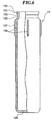
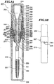
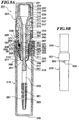
- Figures 1 and 2 show the internal structure of a liquid cosmetic container according to a first embodiment of the present invention.
- Figure 1 shows the remover aperture in the maximum open state with the aperture regulation section lowered.
- Figure 2 shows the remover aperture in the minimum open state with the aperture regulation section raised.
- Figure (A) is a cross section and
- Figure (B) is a side view of the rotation-limiting piece, respectively.
- the liquid cosmetic container 1 in these drawings is comprised of a cap 3, a neck 5, a bar shaped applicator 9, an aperture-regulating ring 7, a remover 13, container main body 19 and the like.
- Figures 3-7 are partial lateral cross sections showing details of the neck, the aperture-regulating ring, the remover, and a bottle and a cover of the container main body of a liquid cosmetic container according to the embodiment.
- the container main body 19 has double structure of a cover 15 with a bottle 17 on its inside.
- the bottle 17 is of a cylindrical shape with a bottom piece which is comprised of a bottom 129 and a lateral section 127 and stores liquid cosmetics in its interior.
- the cover 15 covers the outside of the bottle 17 and likewise has a bottom 139 and a lateral section 137.
- the upper end of the cover 15 extends upwardly to a position higher than the upper end of the bottle 17.
- a longitudinal synchronous engagement groove 133 which extends in a vertical direction is cut into the inner face of the cover 15.
- a longitudinal synchronous engagement rib 85 of the neck 5 engages with the longitudinal synchronous engagement groove 133. This rib 85 can slide vertically in the longitudinal synchronous engagement groove 133.
- the longitudinal synchronous engagement groove 133 is triangular in cross section as shown in Figure 7(B) and a plenty of the grooves 133 are provided on the circumference at a fixed pitch (in this embodiment, there are 20 pieces).
- An upper outer surface 130 (an aperture-regulating ring engaging surface) of the cover 15 has a cylindrical shape, and the diameter of the upper outer surface 130 of the cover 15 is slightly smaller than those of the other parts of the cover 15. Further, the upper outer surface 130 engages with the aperture-regulating ring 7. Furthermore the ring shaped projection 135 is formed on the upper outer surface 130. A ring shaped dent 101 which is formed on a lower inner face of the aperture-regulating ring 7 engages with the projection 135 and rotatably connects the aperture-regulating ring 7 to the container main body 19.
- a rotation-limiting projection 136 is provided on an outer circumference of the cover 15.
- the outer circumference is under the engaging surface 130 of the aperture-regulating ring.
- the projection 136 is an approximately square cube as shown in Figure 7(A) and one projection is provided on the outer circumference in this embodiment.
- the present invention is not limited to the position, the number and the shape of projections given in the embodiment.
- the rotation-limiting projection 136 and the rotation-limiting piece 103 of the aperture-regulating ring 7 (to be discussed below) are disposed on the same horizontal surface so as to abut with each other.
- the rotation-limiting projection 136 limits the rotation of the aperture-regulating ring 7 with respect to the container main body 19 as discussed below.
- the aperture 121 on an upper end of the bottle 17 has a small diameter at its neck section 125.
- the outer circumference 122 of the aperture 121 is formed in the shape of an inverted tapering cone and is adapted to prevent the remover 13 from detaching.
- the lower part of the aperture 121 forms the neck section 125 shaped like a ring groove.
- a step 123 exists between the aperture 121 and the neck section 125.
- the shape of the bottle aperture is related to the fixation structure of the remover 13 to be discussed below.
- the four longitudinal ribs 128 mentioned above are formed on the outer surface of the bottle 17.
- the remover 13 is made from an elastic material typified by a rubber such as NBR and expands freely to some extent.
- the remover 13 is provided with a funnel section 117 which tapers downwardly and has a central aperture 119, an upper hem 115 which extends horizontally towards the outside from an upper end of the funnel section, a suspended section 113 which extends downwardly from an outer edge of the upper hem 115, and a return 111 which extends approximately towards the lower inner side from the suspended section 113.
- the remover 13 is disposed and set on the bottle aperture 121 in the bottle 17 in a state that the return 111 engages with the neck section 125 and the suspended section 113 engages with the outer circumference of the bottle aperture 121 which is the tapering face 122.
- the funnel section 117 abuts with the inner side of the bottle aperture 121 in the bottle 17.
- the inner peripheral edge 111a of the return 111 is hooked to the step 123 which is above the neck section 125 and prevents detachment.
- the upper inner circumference of the cover 15 presses against the suspended section 113 of the remover 13 from the outside and tightly secures the remover 13.
- the return 111 of the remover 13 is maintained in a sandwiched position between the bottle aperture 121 and the cover 15.
- the remover 13 is tightly fixed to the container main body 19 and the airtightness of the bottle is increased.
- the aperture regulating section 11 of the neck 5 abuts with an upper section of the funnel section 117 of the remover 13 from above.
- the funnel section 117 closes inwardly due to its own elasticity and reduces the remover aperture 119 which is an aperture provided at the center of the remover 13.
- a tip 89 of the aperture regulating section 11 depresses the funnel section 117, the funnel section 117 opens outwardly due to elasticity and thus the remover aperture 119 is widened.
- the aperture-regulating ring 7 is adapted so that an upper cylindrical section 93 of small diameter and a lower cylindrical section 99 of large diameter are connected at a step 97 on an outer surface of the aperture-regulating ring 7.
- the lower cylindrical section 99 as stated above, is rotatably connected to an outer upper surface of the container main body 19.
- the inner side of the step 97 is almost in contact with an upper end 131 of the cover 15.
- the ring shaped dent 101 stated above is formed on an inner face of the lower cylindrical section 99.
- a female screw 95 is formed on an inner face of the upper cylindrical section 93 and a male screw 81 formed on an outer circumference of the neck 5 is spirally engaged with the female screw 95.
- the female screw 95 has a single thread with a relatively small lead and, as described in detail below, is provided so that the neck (the aperture regulating section 11) moves between the upper and lower limiting positions when the aperture-regulating ring 7 makes an approximately single rotation.
- An upper inner surface 91 of the female screw 95 is a level circumferential inner surface.
- a longitudinal rib 38 on an outer circumference of the lower end of the cap 3 rotates without contacting with the surface 91. That is to say, the cap 3 widens the aperture of the remover 13 by sinking into the inner diameter of the aperture-regulating ring 7 due to the rotation of the aperture-regulating ring 7.
- the rotation-limiting piece 103 extends from a lower end of the aperture-regulating ring 7.
- the rotation-limiting piece 103 is an approximately square cube and is disposed on the same horizontal surface as the rotation-limiting projection 136 on an outer surface of the cover 15 discussed above.
- the neck 5 has a cylindrical shape with male screws 73 and 81 (a group of male projections may also be used) in two vertical positions.
- the cylindrical aperture regulating section 11 which tapers slightly and downwardly is integrated into the central section 75 so as to extend downwardly and inwardly.
- the tip 89 of the aperture regulating section 11 as discussed above abuts with an inner surface of the funnel section 117 of the remover 13 and regulates the degree of aperture of the remover aperture 119.
- the outer surface of the aperture regulating section 11 is formed as a slightly and downwardly tapered section and is adapted to slide and abut without resistance with respect to the tapered surface of the inner surface of the funnel section 117 of the remover 13.
- a dent 86 is provided on the outer peripheral section of the base 87 of the aperture regulating section 11. The dent 86 is for the purpose of preventing a sink mark when performing plastic injection molding.
- the male screw 81 formed on an outer surface of the lower step of the neck 5 is a left-hand screw
- the male screw 73 formed on an outer surface of the upper step of the neck 5 is a right-hand screw.
- a plurality of longitudinal ribs 85(20 pieces in this embodiment) for synchronous engagement project from an outer circumference of a flange 83 provided under the male screw 81.
- These longitudinal ribs 85 act as longitudinal synchronous engagement ribs (preventing rotation with respect to the container main body) which synchronously engage with the longitudinal synchronous engagement grooves 133 which are cut on the upper inner surface of the cover 15 of the container main body 19.
- the longitudinal ribs 85 enter the longitudinal synchronous engagement grooves 133 and move in a vertical direction along the synchronous engagement grooves 133.
- the neck 5 moves vertically with respect to the remover 13 and the container main body 19 to which the remover 13 is fixed.
- the position of abutment of the remover 13 with the tip 89 of the aperture regulating section 11 on the lower end of the neck 5 varies vertically as a result of the vertical movement of the neck 5, and thus it is possible to regulate the degree of aperture of the remover aperture 119 as described above.
- the neck 5 and the container main body 19 never move relatively to each other.
- the rotation-limiting projection 136 of the container main body 19 and the rotation-limiting piece 103 of the aperture-regulating ring 7 are disposed on the same horizontal surface. Furthermore as shown in Figure 1, the lateral faces of the rotation-limiting piece 103 and the rotation-limiting projection 136 are positioned and designed to abut with each other when the aperture regulating section 11 of the neck 5 is in its lower-limit position. The positioning during assembly will be explained below. At this time, the remover aperture 119 of the remover 13 is in the maximum opened position and the open limit is defined. When the container main body 19 and the aperture-regulating ring 7 are rotated relatively to one another, the aperture regulating section 11 moves upwardly.
- the aperture-regulating ring 7 When the aperture-regulating ring 7 is rotated by roughly one turn and the rotation-limiting projection 136 and the rotation-limiting piece 103 are rotated until their lateral surfaces of the opposite side abut with each other, the aperture-regulating ring 7 cannot be rotated any further and the aperture regulating section 11 is at its upper-limit position. At this time, the remover aperture 119 of the remover 13 is closed most and the closed limit is defined.
- the open and closed limits are determined so that an appropriate amount of liquid cosmetic is removed and the degree of aperture of the remover aperture 119 at each limit is regulated according to the shape of the aperture regulating section 11, the pitch of the screws of the neck 5 and the aperture-regulating ring 7, and the like. Since the rotation-limiting projection 136 and the rotation-limiting piece 103 are provided on the outer surface of the container main body in this embodiment, the open and closed limits can visually be observed. Furthermore since a gap or looseness will result between the container main body and the aperture-regulating ring if the aperture limiting projection is provided on the inner surface of the container main body, it is preferable to provide this projection on an outer surface.
- the degree of aperture of the remover aperture 119 can be estimated by looking at the relative position of the rotation-limiting projection 136 and the rotation-limiting piece 103. Thus it is possible to set an appropriate amount of liquid cosmetics which adhere to the brush 21.
- the male screw 73 on an upper outer surface of the neck 5 is threadably connected with a female screw 37 of the cap 3.
- the inner section of the neck 5 is in the form of a hole cut in the vertical direction (an inner hole 88) through which the bar shaped applicator 9 passes.
- the inner hole 88 narrows towards the lower direction so that the bar shaped applicator 9 may easily be inserted into the container.
- An upper end 71 of the neck 5 abuts with a lower surface of the flange 45 of the bar shaped applicator 9 in a state that the cap 3 (fixed to the bar shaped applicator 9) is closed and the inner section of the container main body is sealed.
- the bar shaped applicator 9 is a bar shaped member having the brush 21 on its lower end and is provided so as to be freely insertable into and extractable from the container main body 19.
- the upper section of the bar shaped applicator 9 is in the form of an insertable section 41 which is a hollow cylindrical section with a relatively large diameter.
- a ring shaped protrusion 43 is formed on the base of this insertable section 41 and when the ring shaped dent 36 on an inner face of the cap 3 engages with the protrusion 43, the cap 3 and the bar shaped applicator 9 are secured.
- the inner hole of the insertable section 41 is a dent for preventing a sink mark.
- the flange 45 is formed under the insertable section 41 of the bar shaped applicator 9.
- the central step 47 of the bar shaped applicator 9 is a hollow bar shaped section which extends downwardly while gradually tapering. This hollow section is a sink mark prevention hole 49.
- a contracted section 51 which is remarkably narrowed is formed under the central step 47.
- the remover aperture 119 is at its tightest position (contracts in a central direction) and, in contrast, a section of the bar shaped applicator 9 with which the remover aperture 119 comes into contact is in its narrowest position accordingly.
- the remover aperture 119 is at its widest position and a section of the applicator 9 with which the remover aperture 119 comes into contact is also at its widest position.
- the lower step 53 of the bar shaped applicator 9 is in the shape of a solid bar.
- the brush 21 composed of brush hair 153 and a guide 151 is connected to the bottom of the lower step 53.
- the brush hair 153 is stroked and excess liquid cosmetics adhered to the brush hair 153 are removed and fall back into the container main body 19.
- the strength of the stroke is determined according to the degree of aperture of the remover aperture 119.
- the cap 3 is in the form of a cylinder with an apex which is composed of lateral sections 33 and a top 31.
- the female screw 37 is formed on the lower section of an inner surface 34.
- the female screw 37 is threadably connected with the male screw 73 formed on an upper outer surface of the neck 5.
- the cap 3 is mounted on the container 1. At this time, a bottom end 39 of the cap 3 is engaged with the upper inner face 91 of the aperture-regulating ring 7.
- the insertable section 41 of the bar shaped applicator 9 is fixed to the central step of the cap 3 as stated above. More precisely, the ring shaped dent 36 is formed on an inner surface of the central step of the cap 3.
- the ring shaped protrusion 43 which is provided above the flange 45 of the bar shaped applicator 9 engages with the ring shaped dent 36 and the cap 3 and the bar shaped applicator 9 are secured. Furthermore the cap 3 and the bar shaped applicator 9 are prevented from rotating by the engagement of the longitudinal rib 42 on an outer surface of the insertable section 41 of the bar shaped applicator 9 with the longitudinal groove 35 on an upper inner surface of the cap 3.
- the remover 13 is mounted on the aperture of the bottle 17. Then the bottle 17 is placed in the cover 15 to form the container main body 19.
- the neck 5 is placed in the aperture-regulating ring 7 from below. As shown in Figure 2, the neck 5 is screwed in until it reaches the upper limit in the aperture-regulating ring 7.
- the rotation-limiting piece 103 of the aperture-regulating ring 7 is assembled in the cover 15 in a position as shown in Figure 2(B), that is to say, in a position that the rotation-limiting piece 103 roughly abuts with the left side of the rotation limiting projection 136 of the cover 15 and in such a manner that the ribs 85 of the neck 15 are engaged with the grooves 133 of the cover 15.
- the ring shaped dent 101 of the aperture-regulating ring 7 and the ring shaped protrusion 135 of the cover 15 are thus engaged and the aperture-regulating ring 7 is brought into rotatable contact with the container main body 19.
- the bar shaped applicator 9 is fitted into and integrated with the cap 3.
- the integrated cap 3 and bar shaped applicator 9 are inserted into the assembled container main body described above and assembly is complete.
- the cap 3 together with the applicator 9 is twisted, separated from the neck 5, and the bar shaped applicator 9 is removed from the container.
- liquid cosmetics in the container main body 19 are adhered to the brush 21 at a lower end of the applicator 9.
- the brush 21 passes through the remover aperture 119 of the remover 13
- the brush 21 is stroked (squeezed) and excess cosmetics adhered thereto are removed and fall back into the container main body 19.
- the degree of aperture of the remover aperture 119 of the remover 13 is regulated as follows.
- the male screw 81 of the neck 5 and the female screw 95 on an inner face of the aperture-regulating ring 7 are rotated relatively to one another since the neck 5 rotates synchronously with the container main body 19.
- the neck 5 is pushed by the aperture-regulating ring 7 which is vertically connected with the container main body 19 and moves in a vertical direction with respect to the container main body 19.
- the funnel section 117 of the remover 13 is pushed by an outer face of the aperture regulating section 11 at a lower section of the neck 5 and the degree of aperture which widens outwardly from the center varies. In this way, the diameter (degree of aperture) of the remover aperture 119 which is the central aperture of the remover 13 varies.
- the container main body 19 and the aperture-regulating ring 7 are only rotated less than a single turn due to the rotation-limiting action of the rotation-limiting projection 136 of the container main body 19 and the rotation-limiting piece 103 of the aperture-regulating ring 7.
- the distance of vertical movement of the neck 5 is limited and the open limit and the closed limit of the remover aperture 119 are determined.
- a user is able to estimate the degree of aperture of the remover aperture 119 by knowing the relative positions of the rotation-limiting projection 136 and the rotation-limiting piece 103.
- Figures 8 and 9 are cross sections showing the inside structure of a liquid cosmetic container according to a second embodiment of the present invention.
- Figure 8 shows the remover aperture at its open limit with the aperture regulating section depressed.
- Figure 9 shows the remover aperture at its closed limit with the aperture regulating section raised.
- Figure (A) is a cross section and
- Figure (B) is a side view of the rotation-limiting piece.
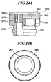
- Figures 10-14 are partial cross sections showing details of a support ring, container main body, remover, aperture-regulating ring, and neck of a liquid cosmetic container according to the second embodiment.
- reference numerals made by adding numeral 200 to the reference numerals of Figure 1 indicate the components and parts same as those of Figure 1 excluding those specified hereinafter.
- the liquid cosmetic container of the second embodiment differs from that of the first embodiment mainly in the following points.
- Figure 15 is a cross section showing the inner structure of the main components of a liquid cosmetic container according to a third embodiment of the present invention. It shows the remover in a fully open position with the aperture regulating section lowered.
- Figure 15(A) is a partial cross section;
- Figure 15(B) is a partial side cross section.
- reference numerals made by adding numeral 200 to the reference numerals in the second embodiment indicate components and parts same as those in the second embodiment excluding those specified hereinafter.
- a liquid cosmetic container 401 comprises a container main body 415 into which liquid cosmetics are contained, a bar shaped applicator 409 which is freely insertable into and retractable from the container main body 415, a cap which closes the aperture of the container main body 415, a neck 405 which is disposed at an upper section of the container main body 415 and which has a section to be engaged with the cap, a remover 413, made from a resilient material and disposed at an upper section of the container main body 415, which has a central aperture and squeezes the outer circumference of the bar shaped applicator 409 using the aperture, an aperture regulating section 411 which extends from a lower section of the neck 405 and abuts with the remover 413, thereby varying the degree of aperture of the central aperture, and an aperture-regulating ring 407 which is rotatably engaged with the container main body 415 and which is threadably engaged with the neck 405.
- a synchronous engagement section is provided between the container main body 415 and the neck 405 in order for the container main body 415 and the neck 405 to freely slide in a vertical direction and to be synchronously engaged with each other.
- the neck 405 and the aperture regulating section 411 are moved in a vertical direction by the rotation of the aperture-regulating ring 407 with respect to the container main body 415 and thus the degree of aperture of the central aperture of the remover 413 is varied.
- the remover 413 is composed of a downwardly tapering member which has a central aperture and a ring section which extends downwardly from an outer circumference of the member.
- the remover 413 is secured by being gripped by an upper support ring 408 which abuts with an upper end of the ring section and a lower support ring 419 which abuts with an inner face of the ring section.
- the remover 413 is securely fixed to the aperture of the container main body 415 by being gripped from above and below by the upper and lower support rings 408 and 419. Due to this type of arrangement, the remover 413 is pressured, whereby the airtightness between its outer face and the inner face of the container main body 415 is further improved.
- Longitudinal grooves 533 for synchronous engagement which extend in a vertical direction are cut on an upper inner face of the container main body 415.
- Longitudinal ribs 565 for synchronous engagement provided on the upper support ring 408 engage with the longitudinal grooves 533.
- a ring shaped dent 532 is formed on an inner face of the upper end of the container main body 415 and engages with the ring shaped protrusion 563 provided on the upper supporting ring 408.
- the upper support ring 408 is unrotatably fixed on an inner face of the container main body 415.
- the lower support ring 419 is in the shape of a bottle neck and comprises a lower ring section 527 and a neck section 525 which extends upwardly from the lower ring section 527.
- the outer circumference of the neck section 525 is slightly indented.
- the lower ring section 527 is mounted on a step 538 of an inner face of the container main body 415.
- the remover 413 is formed from an elastic material typified by a rubber such as NBR and expands freely to an extent.
- the remover 413 is provided with a funnel section 517 which tapers downwardly and has a central aperture 519, an upper hem 515 which extends outwardly and horizontally from an upper end of the funnel section 517, a suspending section 513 which slightly extends downwardly from the outer periphery of the upper hem 515, and a return 511 which extends downwardly and inwardly from the suspending section 513.
- the remover 413 is set and mounted on a bottle aperture 521 in a state that the suspending section 513 engages with an outer circumference of the tapering face of the bottle aperture 521 and the return 511 engages with the neck section 525 with the funnel section 517 against the inner side of the bottle aperture 521.
- An edge section 511a of an inner circumference of the return 511 is hooked on a step 523 provided above the neck section 525, thereby functioning to prevent the detachment.
- the upper inner circumference of the container main body 415 pushes the suspending section 513 of the remover 413 from outside.
- the remover 413 is securely attached, whereby the airtightness is further heightened.
- the remover 413 is engaged with the aperture 521 of the lower support ring 419 from above and the remover 413 and lower support ring 419 are assembled.
- the lower support ring 419 assembled is inserted from the upper aperture of the container main body 415 and mounted on a step 538 provided on an inner face of the container main body 415.
- the remover 413 is gripped between an inner face of the container main body 415 and the lower support ring 419.
- the upper support ring 408 is fitted from the upper aperture of the container main body 415.
- the longitudinal ribs 565 of the upper support ring 408 engage with the longitudinal grooves 533 of the container main body 415, and the ring shaped protruding section 563 of the upper support ring 408 is engaged with the ring shaped dent 532 of the container main body 415.
- the upper support ring 408 is fixed in a non-rotatable state in the container main body 415.
- the remover 413 is fixed by being gripped from above and below by the upper support ring 408 and the container main body 415.
- the remover 413 is accurately fixed in both the vertical and transverse directions to an inner face of the container main body 415 by the upper support ring 408, the lower support ring 419 and the container main body 415.
- the airtightness of the container is improved.
- Liquid cosmetics are sold on the basis of characteristics which are mainly divided into the substance being water-based, oil-based or volatile. The common characteristic which pertains to all these substances is that they have a "Dry Out" effect. Thus, liquid cosmetic containers must be excellent in airtightness and userfriendliness.
- a liquid cosmetic container with a variable remover aperture is provided which is adapted for use with all kinds of liquid cosmetics by the application of the three embodiments explained in the specification.
- liquid cosmetic container of the present invention bring about the following effects.
Landscapes
- Closures For Containers (AREA)
Abstract
A liquid cosmetic container which has a secure mechanism for
defining the limit of the aperture regulation of a remover 13 is provided.
In addition, it is excellent in userfriendliness and design, and the degree
of aperture of the remover 13 is not influenced by the operation of
putting or removing a cap 3. The liquid cosmetic container of the
present invention is provided with the cap 3, and an aperture-regulating
ring 7 engages with an upper outer face of a container main body 19. A
neck 5 which has an aperture regulating section 11 on the rear end
moves in an axial direction in response to rotations of the
aperture-regulating ring 7, thereby varying the diameter of a central
aperture 119 of the remover 13. Furthermore a rotation-limiting piece
103 extends from a lower end of the aperture-regulating ring 7 and a
rotation-limiting projection 136 is provided on an outer face of the
container main body 19 which is under an engaging surface of the
aperture-regulating ring 7. The rotation of the aperture-regulating ring
7 is regulated by the contact of the rotation-limiting piece 103 with the
rotation-limiting projection 136.
Description
The present invention relates to a liquid cosmetic container for
mascara, eyeliner, lip-gloss or the like. More particularly, it relates to a
liquid cosmetic container provided with an applicator, such as a brush,
which is freely insertable and retractable and a remover which has an
aperture to remove excess cosmetics adhered to the applicator. The
liquid cosmetic container can regulate the amount of cosmetics adhered
to the applicator by the regulation of the diameter of the aperture of the
remover.
Many kinds of this type of liquid cosmetic containers which can
vary the amount of cosmetics to be removed are known in the art.
Usually such a container has structure which can vary the degree of
aperture of a remover by the vertical movement of an aperture regulation
part to be in contact with the remover in the container. However this
type of liquid cosmetic container has the disadvantage that the aperture
regulation part moves and the degree of aperture unexpectedly varies
due to torque applied to the neck when putting or removing the cap.
A similar application for a type of container which varies the
degree of aperture of the remover by the tip of an aperture-regulating
ring entails the same problem that when putting the cap, the
aperture-regulating ring rotates by the force of tightening the cap or at
the final tightening stage.
The present invention has an object of providing a liquid cosmetic
container which has a remover with a variable aperture to remove excess
cosmetics adhered to the applicator and which can regulate the amount
of cosmetics adhered to the applicator. Since the liquid cosmetic
container of the present invention has simple structure and a small outer
diameter and the aperture-regulating ring does not rotate when a user
puts the cap on the container in normal use, it has superior design and
userfriendliness, as well as good appearance and applicability to additive
decoration.
Furthermore a liquid cosmetic container is proposed which has an
reliable mechanism for determining the limits (opening and closing
limits) of aperture regulation of the remover.
Furthermore a liquid cosmetic container is proposed which surely
secures the remover and has superior airtightness.
In order to achieve the above object, the liquid cosmetic container
of the present invention comprises a container main body in which liquid
cosmetics are contained, a cap which closes an aperture of the container,
and a bar shaped applicator which is freely insertable into and
retractable from the container main body and which is fixed to the cap.
The liquid cosmetic container further comprises, in the container main
body, a remover which is formed by a resilient body having a central
aperture and which strokes the outer periphery of the bar shaped
applicator using the aperture, an aperture-regulating ring which rotates
freely about the rotational axis on an upper part of the container main
body, and a neck which is movable in an axial direction of the container
main body in response to the rotation of the aperture-regulating ring and
which has an engaging part with the cap. The liquid cosmetic container
is adapted to vary the diameter of the central aperture of the remover
according to the rotational angle of the aperture-regulating ring.
Preferably the liquid cosmetic container of the present invention
comprises the above neck which can slide freely in the vertical direction
and which cannot rotate with respect to the main body, and provides an
aperture regulation section at a lower end section of the neck. The neck
is moved in an axial direction due to the spiral engagement of the neck
with the aperture-regulating ring. This preferably creates pressure of
the aperture regulation section on the remover and the diameter of the
central aperture of the remover is varied.
In other words, there is no relative rotation between the neck and
the main body and even if torque is applied when the cap is engaged with
the neck, the neck will not rotate with respect to the container main body,
and therefore a state of the aperture regulated will not vary.
The liquid cosmetic container of the present invention preferably
comprises a means for limiting the relative rotation of the
aperture-regulating ring and the container main body to a predetermined
range. In the liquid cosmetic container of the present invention, the
diameter of the central aperture is determined by the position of the neck
in an axial direction. That position is determined by the angle of
rotation of the aperture-regulating ring. Therefore in order to determine
the opening and closing limits, there are a method of limiting the
movement of the neck in the axial direction and a method of limiting the
rotational angle of the aperture-regulating ring. In the former,
depending on the structure of the aperture regulating mechanism, there
is a danger that when the user applies a force and turns the
aperture-regulating ring being in the regulated limiting range, a
separating force may be applied to the composite section of the
mechanism due to the force (thrust force) in the axial direction applied to
the neck. On the other hand, there is no such danger as regards the
method of limiting the rotational angle of the aperture-regulating ring.
In the liquid cosmetic container of the present invention, the
aperture-regulating ring engages with an upper outer circumference of
the container main body. A rotation-limiting piece extends from the
lower end of the aperture-regulating ring. A rotation-limiting projection
is provided on an outer face of the container main body which is under
the engagement surface of the aperture-regulating ring. It is preferable
that the rotation of the aperture-regulating ring is regulated by the
contact of the rotation-limiting piece with the rotation-limiting projection.
In this way, it is possible to surely determine a rotational limit of
the aperture-regulating ring. Furthermore manufacture and assembly
of components is easy and the user can understand easily whether the
aperture-regulating ring is at the rotational limit by viewing the position
of an aperture regulation piece.
The actual liquid cosmetic container of the present invention
comprises a container main body into which liquid cosmetics are
contained, a bar shaped applicator which is freely insertable into and
retractable from the container main body, a cap which closes an aperture
of the container and which is fixed to the applicator, a neck which is
disposed on the top of the container main body and which has an
engaging section with the cap, a remover, disposed on the top of the
container main body and comprised of a resilient member having a
central aperture, for stroking the outer periphery of the bar shaped
applicator by means of the aperture, an aperture regulation section,
extending from a lower section of the neck, which abuts with the remover
and varies the diameter of the central aperture, and an
aperture-regulating ring which is rotatably engaged with the container
main body and threadably engaged with the neck. A synchronous
engagement section is provided between the container main body and the
neck in order for the container main body and the neck to freely slide in
a vertical direction and to be synchronously engaged with each other.
The neck and the aperture regulation section are moved vertically by the
rotation of the aperture-regulating ring with respect to the container
main body and thus the degree of aperture of the central aperture of the
remover is varied.
Figures 1 and 2 show the internal structure of a liquid cosmetic
container according to a first embodiment of the present invention.
Figure 1 shows the remover aperture in the maximum open state with
the aperture regulation section lowered. Figure 2 shows the remover
aperture in the minimum open state with the aperture regulation section
raised. Figure (A) is a cross section and Figure (B) is a side view of the
rotation-limiting piece, respectively.
The liquid cosmetic container 1 in these drawings is comprised of
a cap 3, a neck 5, a bar shaped applicator 9, an aperture-regulating ring
7, a remover 13, container main body 19 and the like.
Figures 3-7 are partial lateral cross sections showing details of
the neck, the aperture-regulating ring, the remover, and a bottle and a
cover of the container main body of a liquid cosmetic container according
to the embodiment.
The container main body 19 has double structure of a cover 15
with a bottle 17 on its inside. The bottle 17 is of a cylindrical shape
with a bottom piece which is comprised of a bottom 129 and a lateral
section 127 and stores liquid cosmetics in its interior. The cover 15
covers the outside of the bottle 17 and likewise has a bottom 139 and a
lateral section 137.
The upper end of the cover 15 extends upwardly to a position
higher than the upper end of the bottle 17. A longitudinal synchronous
engagement groove 133 which extends in a vertical direction is cut into
the inner face of the cover 15. A longitudinal synchronous engagement
rib 85 of the neck 5 engages with the longitudinal synchronous
engagement groove 133. This rib 85 can slide vertically in the
longitudinal synchronous engagement groove 133. The longitudinal
synchronous engagement groove 133 is triangular in cross section as
shown in Figure 7(B) and a plenty of the grooves 133 are provided on the
circumference at a fixed pitch (in this embodiment, there are 20 pieces).
Four longitudinal ribs 128 formed on the outer surface of the
aperture of the bottle 17 engage with the longitudinal synchronous
engagement grooves 133. Thus the cover 15 and the bottle 17 are
secured in such a manner that they cannot rotate.
An upper outer surface 130 (an aperture-regulating ring engaging
surface) of the cover 15 has a cylindrical shape, and the diameter of the
upper outer surface 130 of the cover 15 is slightly smaller than those of
the other parts of the cover 15. Further, the upper outer surface 130
engages with the aperture-regulating ring 7. Furthermore the ring
shaped projection 135 is formed on the upper outer surface 130. A ring
shaped dent 101 which is formed on a lower inner face of the
aperture-regulating ring 7 engages with the projection 135 and rotatably
connects the aperture-regulating ring 7 to the container main body 19.
A rotation-limiting projection 136 is provided on an outer
circumference of the cover 15. The outer circumference is under the
engaging surface 130 of the aperture-regulating ring. The projection
136 is an approximately square cube as shown in Figure 7(A) and one
projection is provided on the outer circumference in this embodiment.
Needless to say, the present invention is not limited to the position, the
number and the shape of projections given in the embodiment. The
rotation-limiting projection 136 and the rotation-limiting piece 103 of the
aperture-regulating ring 7 (to be discussed below) are disposed on the
same horizontal surface so as to abut with each other. The
rotation-limiting projection 136 limits the rotation of the
aperture-regulating ring 7 with respect to the container main body 19 as
discussed below.
As shown in detail in Figure 6, the aperture 121 on an upper end
of the bottle 17 has a small diameter at its neck section 125. The outer
circumference 122 of the aperture 121 is formed in the shape of an
inverted tapering cone and is adapted to prevent the remover 13 from
detaching. The lower part of the aperture 121 forms the neck section
125 shaped like a ring groove. A step 123 exists between the aperture
121 and the neck section 125. The shape of the bottle aperture is
related to the fixation structure of the remover 13 to be discussed below.
The four longitudinal ribs 128 mentioned above are formed on the outer
surface of the bottle 17.
The remover 13 is made from an elastic material typified by a
rubber such as NBR and expands freely to some extent. The remover 13
is provided with a funnel section 117 which tapers downwardly and has
a central aperture 119, an upper hem 115 which extends horizontally
towards the outside from an upper end of the funnel section, a
suspended section 113 which extends downwardly from an outer edge of
the upper hem 115, and a return 111 which extends approximately
towards the lower inner side from the suspended section 113. The
remover 13 is disposed and set on the bottle aperture 121 in the bottle
17 in a state that the return 111 engages with the neck section 125 and
the suspended section 113 engages with the outer circumference of the
bottle aperture 121 which is the tapering face 122. In this case, the
funnel section 117 abuts with the inner side of the bottle aperture 121 in
the bottle 17. Furthermore the inner peripheral edge 111a of the return
111 is hooked to the step 123 which is above the neck section 125 and
prevents detachment.
With regard to the remover 13, the upper inner circumference of
the cover 15 presses against the suspended section 113 of the remover
13 from the outside and tightly secures the remover 13.
That is to say, the return 111 of the remover 13 is maintained in a
sandwiched position between the bottle aperture 121 and the cover 15.
Thus the remover 13 is tightly fixed to the container main body 19 and
the airtightness of the bottle is increased.
The aperture regulating section 11 of the neck 5 abuts with an
upper section of the funnel section 117 of the remover 13 from above.
When the aperture regulating section 11 is in a high position, the funnel
section 117 closes inwardly due to its own elasticity and reduces the
remover aperture 119 which is an aperture provided at the center of the
remover 13. When the aperture regulating section 11 is in a low
position, a tip 89 of the aperture regulating section 11 depresses the
funnel section 117, the funnel section 117 opens outwardly due to
elasticity and thus the remover aperture 119 is widened.
The aperture-regulating ring 7 is adapted so that an upper
cylindrical section 93 of small diameter and a lower cylindrical section 99
of large diameter are connected at a step 97 on an outer surface of the
aperture-regulating ring 7. The lower cylindrical section 99, as stated
above, is rotatably connected to an outer upper surface of the container
main body 19. The inner side of the step 97 is almost in contact with an
upper end 131 of the cover 15. The ring shaped dent 101 stated above
is formed on an inner face of the lower cylindrical section 99. A female
screw 95 is formed on an inner face of the upper cylindrical section 93
and a male screw 81 formed on an outer circumference of the neck 5 is
spirally engaged with the female screw 95. The female screw 95 has a
single thread with a relatively small lead and, as described in detail
below, is provided so that the neck (the aperture regulating section 11)
moves between the upper and lower limiting positions when the
aperture-regulating ring 7 makes an approximately single rotation. An
upper inner surface 91 of the female screw 95 is a level circumferential
inner surface. On the surface 91, a longitudinal rib 38 on an outer
circumference of the lower end of the cap 3 rotates without contacting
with the surface 91. That is to say, the cap 3 widens the aperture of the
remover 13 by sinking into the inner diameter of the aperture-regulating
ring 7 due to the rotation of the aperture-regulating ring 7.
The rotation-limiting piece 103 extends from a lower end of the
aperture-regulating ring 7. The rotation-limiting piece 103 is an
approximately square cube and is disposed on the same horizontal
surface as the rotation-limiting projection 136 on an outer surface of the
cover 15 discussed above.
The neck 5 has a cylindrical shape with male screws 73 and 81 (a
group of male projections may also be used) in two vertical positions.
The cylindrical aperture regulating section 11 which tapers slightly and
downwardly is integrated into the central section 75 so as to extend
downwardly and inwardly. The tip 89 of the aperture regulating section
11 as discussed above abuts with an inner surface of the funnel section
117 of the remover 13 and regulates the degree of aperture of the
remover aperture 119. The outer surface of the aperture regulating
section 11 is formed as a slightly and downwardly tapered section and is
adapted to slide and abut without resistance with respect to the tapered
surface of the inner surface of the funnel section 117 of the remover 13.
A dent 86 is provided on the outer peripheral section of the base 87 of
the aperture regulating section 11. The dent 86 is for the purpose of
preventing a sink mark when performing plastic injection molding.
The male screw 81 formed on an outer surface of the lower step of
the neck 5 is a left-hand screw, and the male screw 73 formed on an
outer surface of the upper step of the neck 5 is a right-hand screw. As
shown in Figure 3(B), a plurality of longitudinal ribs 85(20 pieces in this
embodiment) for synchronous engagement project from an outer
circumference of a flange 83 provided under the male screw 81. These
longitudinal ribs 85 act as longitudinal synchronous engagement ribs
(preventing rotation with respect to the container main body) which
synchronously engage with the longitudinal synchronous engagement
grooves 133 which are cut on the upper inner surface of the cover 15 of
the container main body 19. In other words, the longitudinal ribs 85
enter the longitudinal synchronous engagement grooves 133 and move in
a vertical direction along the synchronous engagement grooves 133.
Thus when the container main body 19 and the aperture-regulating ring
7 rotate relatively to one another (for example when one is twisted with
the other held with one hand), the neck 5 moves vertically with respect to
the remover 13 and the container main body 19 to which the remover 13
is fixed. The position of abutment of the remover 13 with the tip 89 of
the aperture regulating section 11 on the lower end of the neck 5 varies
vertically as a result of the vertical movement of the neck 5, and thus it
is possible to regulate the degree of aperture of the remover aperture 119
as described above. Furthermore when the cap 3 is rotated, the neck 5
and the container main body 19 never move relatively to each other.
The relationship between the limitation of rotation by the
aperture-regulating ring and the aperture regulation will be explained
below. The rotation-limiting projection 136 of the container main body
19 and the rotation-limiting piece 103 of the aperture-regulating ring 7
are disposed on the same horizontal surface. Furthermore as shown in
Figure 1, the lateral faces of the rotation-limiting piece 103 and the
rotation-limiting projection 136 are positioned and designed to abut with
each other when the aperture regulating section 11 of the neck 5 is in its
lower-limit position. The positioning during assembly will be explained
below. At this time, the remover aperture 119 of the remover 13 is in
the maximum opened position and the open limit is defined. When the
container main body 19 and the aperture-regulating ring 7 are rotated
relatively to one another, the aperture regulating section 11 moves
upwardly. When the aperture-regulating ring 7 is rotated by roughly
one turn and the rotation-limiting projection 136 and the
rotation-limiting piece 103 are rotated until their lateral surfaces of the
opposite side abut with each other, the aperture-regulating ring 7 cannot
be rotated any further and the aperture regulating section 11 is at its
upper-limit position. At this time, the remover aperture 119 of the
remover 13 is closed most and the closed limit is defined.
The open and closed limits are determined so that an appropriate
amount of liquid cosmetic is removed and the degree of aperture of the
remover aperture 119 at each limit is regulated according to the shape of
the aperture regulating section 11, the pitch of the screws of the neck 5
and the aperture-regulating ring 7, and the like. Since the
rotation-limiting projection 136 and the rotation-limiting piece 103 are
provided on the outer surface of the container main body in this
embodiment, the open and closed limits can visually be observed.
Furthermore since a gap or looseness will result between the container
main body and the aperture-regulating ring if the aperture limiting
projection is provided on the inner surface of the container main body, it
is preferable to provide this projection on an outer surface. The degree
of aperture of the remover aperture 119 can be estimated by looking at
the relative position of the rotation-limiting projection 136 and the
rotation-limiting piece 103. Thus it is possible to set an appropriate
amount of liquid cosmetics which adhere to the brush 21.
The male screw 73 on an upper outer surface of the neck 5 is
threadably connected with a female screw 37 of the cap 3. The inner
section of the neck 5 is in the form of a hole cut in the vertical direction
(an inner hole 88) through which the bar shaped applicator 9 passes.
The inner hole 88 narrows towards the lower direction so that the bar
shaped applicator 9 may easily be inserted into the container.
An upper end 71 of the neck 5 abuts with a lower surface of the
flange 45 of the bar shaped applicator 9 in a state that the cap 3 (fixed to
the bar shaped applicator 9) is closed and the inner section of the
container main body is sealed.
The bar shaped applicator 9 is a bar shaped member having the
brush 21 on its lower end and is provided so as to be freely insertable
into and extractable from the container main body 19. The upper
section of the bar shaped applicator 9 is in the form of an insertable
section 41 which is a hollow cylindrical section with a relatively large
diameter. A ring shaped protrusion 43 is formed on the base of this
insertable section 41 and when the ring shaped dent 36 on an inner face
of the cap 3 engages with the protrusion 43, the cap 3 and the bar
shaped applicator 9 are secured. The inner hole of the insertable
section 41 is a dent for preventing a sink mark.
The flange 45 is formed under the insertable section 41 of the bar
shaped applicator 9. The central step 47 of the bar shaped applicator 9
is a hollow bar shaped section which extends downwardly while
gradually tapering. This hollow section is a sink mark prevention hole
49. A contracted section 51 which is remarkably narrowed is formed
under the central step 47. When the bar shaped applicator 9 is inserted
in the container 1 and the cap 3 is put, the remover aperture 119 of the
remover 13 moves to the contracted section 51 and a tapering section 52
which is above the contracted section 51. In Figure 2, the remover
aperture 119 is at its tightest position (contracts in a central direction)
and, in contrast, a section of the bar shaped applicator 9 with which the
remover aperture 119 comes into contact is in its narrowest position
accordingly. In Figure 1, the remover aperture 119 is at its widest
position and a section of the applicator 9 with which the remover
aperture 119 comes into contact is also at its widest position. Although
the liquid cosmetic is sealed in the container due to the contact
(tightening) of the remover aperture 119 with an outer circumference of
the bar shaped applicator 9, the above structure maintains an
appropriate tightening force.
The lower step 53 of the bar shaped applicator 9 is in the shape of
a solid bar. The brush 21 composed of brush hair 153 and a guide 151
is connected to the bottom of the lower step 53. When the brush 21
with which liquid cosmetics are soaked is extracted from the container
main body 19 and passes through the remover aperture 119 of the
remover 13, the brush hair 153 is stroked and excess liquid cosmetics
adhered to the brush hair 153 are removed and fall back into the
container main body 19. The strength of the stroke is determined
according to the degree of aperture of the remover aperture 119. Thus,
by regulating the degree of aperture of the remover aperture 119 by the
mechanism discussed above, it is possible to regulate the amount of
liquid cosmetics adhered to the brush 21.
The cap 3 is in the form of a cylinder with an apex which is
composed of lateral sections 33 and a top 31. The female screw 37 is
formed on the lower section of an inner surface 34. The female screw 37
is threadably connected with the male screw 73 formed on an upper
outer surface of the neck 5. The cap 3 is mounted on the container 1.
At this time, a bottom end 39 of the cap 3 is engaged with the upper
inner face 91 of the aperture-regulating ring 7.
The insertable section 41 of the bar shaped applicator 9 is fixed to
the central step of the cap 3 as stated above. More precisely, the ring
shaped dent 36 is formed on an inner surface of the central step of the
cap 3. The ring shaped protrusion 43 which is provided above the
flange 45 of the bar shaped applicator 9 engages with the ring shaped
dent 36 and the cap 3 and the bar shaped applicator 9 are secured.
Furthermore the cap 3 and the bar shaped applicator 9 are prevented
from rotating by the engagement of the longitudinal rib 42 on an outer
surface of the insertable section 41 of the bar shaped applicator 9 with
the longitudinal groove 35 on an upper inner surface of the cap 3.
The assembling process of the liquid cosmetic container according
to Figure 1 will now be explained.
First the remover 13 is mounted on the aperture of the bottle 17.
Then the bottle 17 is placed in the cover 15 to form the container main
body 19. The neck 5 is placed in the aperture-regulating ring 7 from
below. As shown in Figure 2, the neck 5 is screwed in until it reaches
the upper limit in the aperture-regulating ring 7. The rotation-limiting
piece 103 of the aperture-regulating ring 7 is assembled in the cover 15
in a position as shown in Figure 2(B), that is to say, in a position that the
rotation-limiting piece 103 roughly abuts with the left side of the rotation
limiting projection 136 of the cover 15 and in such a manner that the
ribs 85 of the neck 15 are engaged with the grooves 133 of the cover 15.
The ring shaped dent 101 of the aperture-regulating ring 7 and the ring
shaped protrusion 135 of the cover 15 are thus engaged and the
aperture-regulating ring 7 is brought into rotatable contact with the
container main body 19. On the other hand, the bar shaped applicator
9 is fitted into and integrated with the cap 3. The integrated cap 3 and
bar shaped applicator 9 are inserted into the assembled container main
body described above and assembly is complete.
The overall operation including the mechanism for regulating the
amount of liquid cosmetics adhered to the applicator in the liquid
cosmetic container shown in Figure 1 will be explained below.
During use, the cap 3 together with the applicator 9 is twisted,
separated from the neck 5, and the bar shaped applicator 9 is removed
from the container. At this time, liquid cosmetics in the container main
body 19 are adhered to the brush 21 at a lower end of the applicator 9.
However, when the brush 21 passes through the remover aperture 119 of
the remover 13, the brush 21 is stroked (squeezed) and excess cosmetics
adhered thereto are removed and fall back into the container main body
19.
The degree of aperture of the remover aperture 119 of the remover
13 is regulated as follows. When the container main body 19 is gripped
in the fingers and the aperture-regulating ring 7 is rotated, the male
screw 81 of the neck 5 and the female screw 95 on an inner face of the
aperture-regulating ring 7 are rotated relatively to one another since the
neck 5 rotates synchronously with the container main body 19. In this
way, the neck 5 is pushed by the aperture-regulating ring 7 which is
vertically connected with the container main body 19 and moves in a
vertical direction with respect to the container main body 19. When the
neck 5 moves vertically, the funnel section 117 of the remover 13 is
pushed by an outer face of the aperture regulating section 11 at a lower
section of the neck 5 and the degree of aperture which widens outwardly
from the center varies. In this way, the diameter (degree of aperture) of
the remover aperture 119 which is the central aperture of the remover 13
varies.
In other words, when the neck 5 is in a high position (refer to
Figure 2), the diameter of the aperture of the remover 13 decreases and
the remover aperture 119 forms a closed limit. The brush 21 is strongly
stroked, thereby reducing the amount of cosmetics which are adhered to
the brush 21 extracted from the container. On the other hand, when
the neck 5 is in a low position (refer to Figure 1), the diameter of the
aperture of the remover 13 increases and the remover aperture forms an
open limit. The brush 21 is not stroked very strongly, thereby
increasing the amount of cosmetics which are adhered to the brush 21
extracted from the container.
The container main body 19 and the aperture-regulating ring 7
are only rotated less than a single turn due to the rotation-limiting action
of the rotation-limiting projection 136 of the container main body 19 and
the rotation-limiting piece 103 of the aperture-regulating ring 7. The
distance of vertical movement of the neck 5 is limited and the open limit
and the closed limit of the remover aperture 119 are determined. A user
is able to estimate the degree of aperture of the remover aperture 119 by
knowing the relative positions of the rotation-limiting projection 136 and
the rotation-limiting piece 103.
Figures 8 and 9 are cross sections showing the inside structure of
a liquid cosmetic container according to a second embodiment of the
present invention. Figure 8 shows the remover aperture at its open limit
with the aperture regulating section depressed. Figure 9 shows the
remover aperture at its closed limit with the aperture regulating section
raised. Figure (A) is a cross section and Figure (B) is a side view of the
rotation-limiting piece.
Figures 10-14 are partial cross sections showing details of a
support ring, container main body, remover, aperture-regulating ring,
and neck of a liquid cosmetic container according to the second
embodiment.
In these figures, reference numerals made by adding numeral 200
to the reference numerals of Figure 1 indicate the components and parts
same as those of Figure 1 excluding those specified hereinafter.
The liquid cosmetic container of the second embodiment differs
from that of the first embodiment mainly in the following points.
Figure 15 is a cross section showing the inner structure of the
main components of a liquid cosmetic container according to a third
embodiment of the present invention. It shows the remover in a fully
open position with the aperture regulating section lowered. Figure 15(A)
is a partial cross section; Figure 15(B) is a partial side cross section. In
the figures, reference numerals made by adding numeral 200 to the
reference numerals in the second embodiment indicate components and
parts same as those in the second embodiment excluding those specified
hereinafter.
A liquid cosmetic container 401 according to the third
embodiment comprises a container main body 415 into which liquid
cosmetics are contained, a bar shaped applicator 409 which is freely
insertable into and retractable from the container main body 415, a cap
which closes the aperture of the container main body 415, a neck 405
which is disposed at an upper section of the container main body 415
and which has a section to be engaged with the cap, a remover 413,
made from a resilient material and disposed at an upper section of the
container main body 415, which has a central aperture and squeezes the
outer circumference of the bar shaped applicator 409 using the aperture,
an aperture regulating section 411 which extends from a lower section of
the neck 405 and abuts with the remover 413, thereby varying the degree
of aperture of the central aperture, and an aperture-regulating ring 407
which is rotatably engaged with the container main body 415 and which
is threadably engaged with the neck 405. A synchronous engagement
section is provided between the container main body 415 and the neck
405 in order for the container main body 415 and the neck 405 to freely
slide in a vertical direction and to be synchronously engaged with each
other. The neck 405 and the aperture regulating section 411 are moved
in a vertical direction by the rotation of the aperture-regulating ring 407
with respect to the container main body 415 and thus the degree of
aperture of the central aperture of the remover 413 is varied. The
remover 413 is composed of a downwardly tapering member which has a
central aperture and a ring section which extends downwardly from an
outer circumference of the member. The remover 413 is secured by
being gripped by an upper support ring 408 which abuts with an upper
end of the ring section and a lower support ring 419 which abuts with an
inner face of the ring section.
In other words, the remover 413 is securely fixed to the aperture
of the container main body 415 by being gripped from above and below
by the upper and lower support rings 408 and 419. Due to this type of
arrangement, the remover 413 is pressured, whereby the airtightness
between its outer face and the inner face of the container main body 415
is further improved.
The lower support ring 419 is in the shape of a bottle neck and
comprises a lower ring section 527 and a neck section 525 which extends
upwardly from the lower ring section 527. The outer circumference of
the neck section 525 is slightly indented. The lower ring section 527 is
mounted on a step 538 of an inner face of the container main body 415.
The remover 413 is formed from an elastic material typified by a
rubber such as NBR and expands freely to an extent. The remover 413
is provided with a funnel section 517 which tapers downwardly and has
a central aperture 519, an upper hem 515 which extends outwardly and
horizontally from an upper end of the funnel section 517, a suspending
section 513 which slightly extends downwardly from the outer periphery
of the upper hem 515, and a return 511 which extends downwardly and
inwardly from the suspending section 513. The remover 413 is set and
mounted on a bottle aperture 521 in a state that the suspending section
513 engages with an outer circumference of the tapering face of the
bottle aperture 521 and the return 511 engages with the neck section
525 with the funnel section 517 against the inner side of the bottle
aperture 521. An edge section 511a of an inner circumference of the
return 511 is hooked on a step 523 provided above the neck section 525,
thereby functioning to prevent the detachment.
The upper inner circumference of the container main body 415
pushes the suspending section 513 of the remover 413 from outside.
Thus the remover 413 is securely attached, whereby the airtightness is
further heightened.
During assembly, firstly the remover 413 is engaged with the
aperture 521 of the lower support ring 419 from above and the remover
413 and lower support ring 419 are assembled. The lower support ring
419 assembled is inserted from the upper aperture of the container main
body 415 and mounted on a step 538 provided on an inner face of the
container main body 415. The remover 413 is gripped between an inner
face of the container main body 415 and the lower support ring 419.
Next the upper support ring 408 is fitted from the upper aperture of the
container main body 415. The longitudinal ribs 565 of the upper
support ring 408 engage with the longitudinal grooves 533 of the
container main body 415, and the ring shaped protruding section 563 of
the upper support ring 408 is engaged with the ring shaped dent 532 of
the container main body 415. The upper support ring 408 is fixed in a
non-rotatable state in the container main body 415. In this embodiment,
the remover 413 is fixed by being gripped from above and below by the
upper support ring 408 and the container main body 415. Thus the
remover 413 is accurately fixed in both the vertical and transverse
directions to an inner face of the container main body 415 by the upper
support ring 408, the lower support ring 419 and the container main
body 415. As a result, the airtightness of the container is improved.
Liquid cosmetics are sold on the basis of characteristics which are
mainly divided into the substance being water-based, oil-based or volatile.
The common characteristic which pertains to all these substances is that
they have a "Dry Out" effect. Thus, liquid cosmetic containers must be
excellent in airtightness and userfriendliness. A liquid cosmetic
container with a variable remover aperture is provided which is adapted
for use with all kinds of liquid cosmetics by the application of the three
embodiments explained in the specification.
As explained above, the liquid cosmetic container of the present
invention bring about the following effects.
Claims (14)
- A liquid cosmetic container comprising:a container main body which contains liquid cosmetics;a cap which closes an aperture of a container; anda bar shaped applicator which is freely insertable into and detachable from said main body and which is fixed to said cap, wherein a remover which is composed of an elastic body having a central aperture and strokes an outer circumference of said bar shaped applicator by said aperture is provided in said container main body; an aperture-regulating ring which freely rotates about an axial direction is provided at an upper part of said container main body; a neck which has a section engaged with said cap and can move in an axial direction of said container main body in response to rotations of said aperture-regulating ring is provided; and a diameter of said central aperture of said remover is varied according to a rotational angle of said aperture-regulating ring.
- A liquid cosmetic container according to claim 1, wherein said neck is provided so as to be freely slidable in a vertical direction and non-rotatable with respect to said main body; an aperture regulating section is provided on a lower end of said neck; and said neck is moved in an axial direction due to spiral engagement of said aperture-regulating ring with said neck and a diameter of said central aperture of said remover is varied in response to pressure of said aperture regulation section on said remover according to the movement of said neck.
- A liquid cosmetic container according to claim 1 or claim 2, wherein regulation of an aperture diameter of said remover is performed by a rotation of said aperture-regulating ring through an angle of 360° or less.
- A liquid cosmetic container according to claim 1 or claim 2, wherein means for limiting a rotation of said aperture-regulating ring to a predetermined range are provided between said aperture-regulating ring and said container main body.
- A liquid cosmetic container according to claim 4, wherein said aperture-regulating ring is engaged with an upper outer circumference of said container main body; a rotation-limiting piece extends from a lower end of said aperture-regulating ring; a rotation-limiting projection is provided on an outer face of said container main body, said outer face is under an engaging face of said aperture-regulating ring; and a rotation of said aperture-regulating ring is limited by contact of said rotation-limiting piece with said rotation-limiting projection.
- A liquid cosmetic container according to any one of claims 1 through 5, wherein said container main body comprising:a bottle which said remover is placed on its aperture; anda cover which covers the bottle.
- A liquid cosmetic container according to any one of claims 1 through 5, wherein said container main body is a cylindrical body with a base whose upper section is opened; a support ring which is retained at a step formed at an upper section of an interior of said cylindrical body is further provided; said neck engages with said container main body through said support ring so as to be freely slidable in a vertical direction and non-rotatable; and said remover is fixed to said support ring.
- A liquid cosmetic container comprising:a container main body in which liquid cosmetics are contained;a bar shaped applicator which is freely insertable into and detachable from said container main body;a cap which closes an aperture of a container and is fixed to said applicator;a neck, disposed on an upper section of said container main body, which has a section engaged with said cap;a remover, disposed on an upper section of said container main body and composed of a resilient material having a central aperture, for stroking an outer circumference of said bar shaped applicator by the aperture;an aperture regulating section which extends from a lower section of said neck, abuts with said remover, and varies a diameter of the central aperture of said remover; andan aperture-regulating ring which rotatably engages with said container main body and spirally engages with said neck, wherein a synchronous engagement section is provided between said container main body and said neck in order for said container main body and said neck to freely slide in a vertical direction and to be synchronously engaged with each other; and said neck and said aperture regulating section are moved in a vertical direction by a rotation of said aperture-regulating ring with respect to said container main body, whereby a degree of aperture of the central aperture of said remover is varied.
- A liquid cosmetic container according to claim 8, wherein means for regulating rotations of said aperture-regulating ring are further provided, whereby a regulation limit of a diameter of the central aperture of said remover is defined.
- A liquid cosmetic container according to claim 8, wherein said aperture-regulating ring engages with an upper outer circumference of said container main body; a rotation limiting piece extends from a lower end of said aperture-regulating ring; a rotation limiting projection is provided on an outer face of said container main body which is under an engaging surface of said aperture-regulating ring; and rotations of said aperture-regulating ring are regulated by contact of said rotation limiting piece with said rotation limiting projection.
- A liquid cosmetic container according to any one of claims 8 through 10, wherein said container main body comprising:a bottle which said remover is placed on its aperture; anda cover which covers said bottle.
- A liquid cosmetic container according to any one of claims 8 through 10, wherein said container main body is a cylindrical body with a base whose upper section is opened; a support ring which is retained at a step formed at an upper section of an interior of said cylindrical body is further provided; said neck engages with said container main body through said support ring so as to be freely slidable in a vertical direction and non-rotatable; and said remover is fixed to said support ring.
- A liquid cosmetic container according to claim 12, wherein said remover is composed of a downwardly tapering member which has a central aperture and a ring section which extends in a lower direction from an outer circumference of said remover; an upper support ring which abuts with an upper end of said ring section of said remover and a lower support ring which abuts with an inner face of said ring section of said remover are provided; and said remover is gripped between both of said support rings.
- A liquid cosmetic container according to claim 13, wherein said upper support ring is fixed to said container main body; and a synchronous engagement section is provided between an inner face of said upper support ring and said neck in order for said upper support ring and said neck to freely slide in a vertical direction and to be synchronously engaged with each other.
Applications Claiming Priority (3)
| Application Number | Priority Date | Filing Date | Title |
|---|---|---|---|
| JP6393298 | 1998-03-02 | ||
| JP06393298A JP3410014B2 (en) | 1998-03-02 | 1998-03-02 | Liquid cosmetic container |
| PCT/JP1998/001321 WO1999044464A1 (en) | 1998-03-02 | 1998-03-25 | Liquefied cosmetic container |
Publications (2)
| Publication Number | Publication Date |
|---|---|
| EP1060686A1 true EP1060686A1 (en) | 2000-12-20 |
| EP1060686A4 EP1060686A4 (en) | 2004-10-20 |
Family
ID=13243626
Family Applications (1)
| Application Number | Title | Priority Date | Filing Date |
|---|---|---|---|
| EP98910995A Withdrawn EP1060686A4 (en) | 1998-03-02 | 1998-03-25 | Liquefied cosmetic container |
Country Status (4)
| Country | Link |
|---|---|
| US (1) | US6270273B1 (en) |
| EP (1) | EP1060686A4 (en) |
| JP (1) | JP3410014B2 (en) |
| WO (1) | WO1999044464A1 (en) |
Cited By (3)
| Publication number | Priority date | Publication date | Assignee | Title |
|---|---|---|---|---|
| US7946778B2 (en) | 2005-10-10 | 2011-05-24 | L'oreal | Device for packaging and applying a composition and method of using same |
| US8007191B2 (en) | 2005-04-19 | 2011-08-30 | L'oreal | Packaging and applicator device for a composition |
| WO2016020609A1 (en) | 2014-08-04 | 2016-02-11 | Chanel Parfums Beaute | Mechanical attachment of two parts of a container for a cosmetic product |
Families Citing this family (25)
| Publication number | Priority date | Publication date | Assignee | Title |
|---|---|---|---|---|
| DE60134019D1 (en) | 2000-03-31 | 2008-06-26 | Cosmetic Technologies Llc | DEVICE FOR DISTRIBUTING PERSONALIZED COSMETICS |
| JP2001327326A (en) * | 2000-05-24 | 2001-11-27 | Yoshino Kogyosho Co Ltd | Mascara container |
| DE10029378B4 (en) * | 2000-06-20 | 2005-06-16 | Geka Brush Gmbh | Application device for cosmetic liquids, in particular mascara test applicator |
| US6412658B1 (en) | 2001-06-01 | 2002-07-02 | Imx Labs, Inc. | Point-of-sale body powder dispensing system |
| US8636173B2 (en) | 2001-06-01 | 2014-01-28 | Cosmetic Technologies, L.L.C. | Point-of-sale body powder dispensing system |
| CA2461307C (en) | 2001-09-24 | 2011-01-11 | Imx Labs, Inc. | Apparatus and method for custom cosmetic dispensing |
| US8573263B2 (en) | 2001-09-24 | 2013-11-05 | Cosmetic Technologies, Llc | Apparatus and method for custom cosmetic dispensing |
| US6615881B2 (en) | 2001-09-24 | 2003-09-09 | Imx Labs, Inc. | Apparatus and method for custom cosmetic dispensing |
| US7410615B2 (en) * | 2002-01-24 | 2008-08-12 | Perkinelmer Las, Inc. | Precision liquid dispensing system |
| US20030232310A1 (en) * | 2002-06-14 | 2003-12-18 | Matthews Alan B. | Dental whitening |
| FR2851434B1 (en) * | 2003-02-24 | 2005-04-08 | Oreal | PACKAGING AND EXTENDED APPLICATION DEVICE |
| WO2006020189A2 (en) | 2004-07-19 | 2006-02-23 | Barthomolew Julie R | Customized retail point of sale dispensing methods |
| CA2587098C (en) | 2004-11-08 | 2015-12-29 | Julie R. Bartholomew | Automated customized cosmetic dispenser |
| US20090214285A1 (en) * | 2008-02-27 | 2009-08-27 | Yong Hoon Cho | Cosmetic holders with removable reservoir |
| DE102008052895B3 (en) * | 2008-10-23 | 2010-02-04 | Geka Brush Gmbh | Cosmetic unit with adjustable scraper |
| US20100129132A1 (en) * | 2008-11-26 | 2010-05-27 | Zen Design Solutions Limited | Wiper member for a container for packaging and dispensing products |
| DE202009004528U1 (en) * | 2009-04-01 | 2010-08-19 | Schwan-Stabilo Cosmetics Gmbh & Co. Kg | Application device with scraping zone adjustable over a crumple zone |
| US20110114112A1 (en) * | 2009-11-17 | 2011-05-19 | Yi-Li Tsai | Lash brush with adjustable bristle arrangement |
| US9167881B2 (en) * | 2013-08-05 | 2015-10-27 | Je Matadi, Inc. | Container for storing and displaying a cosmetic product |
| CN107635431B (en) | 2015-06-08 | 2022-01-11 | 化妆品科技有限责任公司 | Automatic dispensing system for cosmetic samples |
| US10667594B2 (en) | 2016-02-04 | 2020-06-02 | Sinwa Corporation | Wiper for cosmetic container |
| US10660419B2 (en) * | 2016-12-15 | 2020-05-26 | Elc Management Llc | Packaged skin treatment composition and method |
| CN107518565A (en) * | 2017-10-05 | 2017-12-29 | 谢桐利 | A kind of adjustable quantitative device of cosmetics content |
| JP6606657B2 (en) | 2018-01-23 | 2019-11-20 | 株式会社トキワ | Application container |
| KR102280030B1 (en) * | 2019-08-14 | 2021-07-21 | 주식회사 에이엔피 | Cosmetics container with double sealing structure |
Family Cites Families (24)
| Publication number | Priority date | Publication date | Assignee | Title |
|---|---|---|---|---|
| US4241743A (en) * | 1979-03-13 | 1980-12-30 | Noxell Corporation | Adjustable wiper container and applicator assembly for cosmetics and the like |
| JPS5886017U (en) * | 1981-12-07 | 1983-06-10 | 株式会社吉野工業所 | Cosmetic liquid storage container |
| JPS58119312U (en) * | 1982-02-05 | 1983-08-15 | 株式会社吉野工業所 | Cosmetics application container |
| JPS58119316U (en) * | 1982-02-10 | 1983-08-15 | 株式会社吉野工業所 | Cosmetics application container |
| JPS58122511U (en) * | 1982-02-15 | 1983-08-20 | 株式会社吉野工業所 | Cosmetic liquid container |
| JPS58125513U (en) * | 1982-02-17 | 1983-08-26 | 株式会社吉野工業所 | Cosmetic liquid container |
| FR2545008A1 (en) * | 1983-04-27 | 1984-11-02 | Snap Duroc Sa | Fluid-substance applicator with adjustable drying |
| JPS6114330A (en) | 1984-06-28 | 1986-01-22 | 南村 仁一 | Automatic intermittent sprinkler |
| JPS6114329A (en) | 1984-06-29 | 1986-01-22 | 株式会社東芝 | Piping apparatus for preventing freezing |
| JPS6117699A (en) | 1984-07-02 | 1986-01-25 | 日立造船株式会社 | Stirring blade in shield drilling machine |
| JPH065440B2 (en) | 1984-07-10 | 1994-01-19 | コニカ株式会社 | Cleaning device |
| JPS6138500A (en) | 1984-07-30 | 1986-02-24 | 日新ハイボルテ−ジ株式会社 | Irradiation window |
| JPH0681371B2 (en) | 1984-11-21 | 1994-10-12 | 株式会社日立製作所 | Gas insulated switchgear |
| JPS61124207U (en) * | 1985-01-21 | 1986-08-05 | ||
| IT209235Z2 (en) * | 1985-10-18 | 1988-09-20 | Maplast Srl | CONTAINER FOR COSMETICS. |
| FR2605198B1 (en) * | 1986-10-16 | 1991-04-05 | Oreal | MAKE-UP ASSEMBLY, PARTICULARLY FOR THE EYELASHES, COMPRISING A STIFFENING DEVICE |
| JPH0388409A (en) | 1989-08-30 | 1991-04-12 | Nec Corp | Delay circuit |
| JP2587726Y2 (en) * | 1989-12-27 | 1998-12-24 | 竹内工業 株式会社 | Storage container for liquid cosmetics, etc. |
| JPH084889Y2 (en) * | 1990-02-02 | 1996-02-14 | ポーラ化成工業株式会社 | Storage container for liquid cosmetics, etc. |
| JP3390980B2 (en) * | 1994-01-28 | 2003-03-31 | 株式会社吉野工業所 | Mascara applicator |
| JP3394314B2 (en) * | 1994-03-08 | 2003-04-07 | 株式会社コーセー | Mascara applicator |
| JPH084889A (en) | 1994-06-15 | 1996-01-12 | Nissan Motor Co Ltd | Hydraulic circuit for shift control of automatic transmission |
| JP3457381B2 (en) * | 1994-06-29 | 2003-10-14 | 株式会社コーセー | Mascara applicator |
| JPH114714A (en) * | 1997-06-18 | 1999-01-12 | Suzuno Kasei Kk | Liquid cosmetic casing |
-
1998
- 1998-03-02 JP JP06393298A patent/JP3410014B2/en not_active Expired - Fee Related
- 1998-03-25 US US09/581,425 patent/US6270273B1/en not_active Expired - Fee Related
- 1998-03-25 EP EP98910995A patent/EP1060686A4/en not_active Withdrawn
- 1998-03-25 WO PCT/JP1998/001321 patent/WO1999044464A1/en not_active Ceased
Cited By (4)
| Publication number | Priority date | Publication date | Assignee | Title |
|---|---|---|---|---|
| US8007191B2 (en) | 2005-04-19 | 2011-08-30 | L'oreal | Packaging and applicator device for a composition |
| US7946778B2 (en) | 2005-10-10 | 2011-05-24 | L'oreal | Device for packaging and applying a composition and method of using same |
| WO2016020609A1 (en) | 2014-08-04 | 2016-02-11 | Chanel Parfums Beaute | Mechanical attachment of two parts of a container for a cosmetic product |
| US10104953B2 (en) | 2014-08-04 | 2018-10-23 | Chanel Parfums Beaute | Mechanical coupling of a cosmetic product container |
Also Published As
| Publication number | Publication date |
|---|---|
| JPH11244043A (en) | 1999-09-14 |
| JP3410014B2 (en) | 2003-05-26 |
| EP1060686A4 (en) | 2004-10-20 |
| WO1999044464A1 (en) | 1999-09-10 |
| US6270273B1 (en) | 2001-08-07 |
Similar Documents
| Publication | Publication Date | Title |
|---|---|---|
| US6270273B1 (en) | Liquid cosmetic container | |
| US11730249B2 (en) | Cosmetic jars with sweep collar | |
| JP2518509Y2 (en) | Makeup unit | |
| US4407311A (en) | Make-up unit with an adjustable wiper device | |
| US10575619B2 (en) | Cosmetic container with closure | |
| KR101965291B1 (en) | Stick typed cosmetic container for controlling the rotation angle of rotary body at a fixed angle | |
| EP2515694B1 (en) | Application device for products | |
| CN102763976A (en) | Cosmetics unit with dual arm applicator | |
| KR102313212B1 (en) | Cosmetic vessel | |
| CS202013B2 (en) | Closing bottle cap | |
| US9877564B2 (en) | Liquid content container comprising tension member | |
| US10874193B2 (en) | Wheel actuated cosmetic stick | |
| CN108497680A (en) | Rotary liquid cosmetic pen | |
| KR200462304Y1 (en) | Foundation vessel | |
| US7255510B2 (en) | Rotating dispenser for liquid cosmetics | |
| US20240315423A1 (en) | Cartridge core assembly and cosmetic container comprising cartridge core assembly | |
| CN114291414A (en) | One-key lid with decorative portion | |
| JPH10117840A (en) | Liquid cosmetic case | |
| KR102096492B1 (en) | The cosmetic container in which the shape of the application member is changed | |
| JP7798696B2 (en) | Wearing equipment | |
| JP2551942Y2 (en) | Liquid container application container | |
| EP3780992B1 (en) | Device for applying a cosmetic product with a dressing, kit and associated dressing method | |
| KR19990021984U (en) | Mascara bottle having packings | |
| JP7733617B2 (en) | Cap with applicator and applicator container | |
| KR102569160B1 (en) | Stick vessel |
Legal Events
| Date | Code | Title | Description |
|---|---|---|---|
| PUAI | Public reference made under article 153(3) epc to a published international application that has entered the european phase |
Free format text: ORIGINAL CODE: 0009012 |
|
| 17P | Request for examination filed |
Effective date: 20001002 |
|
| AK | Designated contracting states |
Kind code of ref document: A1 Designated state(s): DE FR |
|
| A4 | Supplementary search report drawn up and despatched |
Effective date: 20040902 |
|
| STAA | Information on the status of an ep patent application or granted ep patent |
Free format text: STATUS: THE APPLICATION IS DEEMED TO BE WITHDRAWN |
|
| 18D | Application deemed to be withdrawn |
Effective date: 20041117 |