EP1061018A1 - Vorrichtung zur Handhabung von Planschnittprodukten - Google Patents
Vorrichtung zur Handhabung von Planschnittprodukten Download PDFInfo
- Publication number
- EP1061018A1 EP1061018A1 EP20000111328 EP00111328A EP1061018A1 EP 1061018 A1 EP1061018 A1 EP 1061018A1 EP 20000111328 EP20000111328 EP 20000111328 EP 00111328 A EP00111328 A EP 00111328A EP 1061018 A1 EP1061018 A1 EP 1061018A1
- Authority
- EP
- European Patent Office
- Prior art keywords
- plate
- pull
- follower plate
- follower
- projection
- Prior art date
- Legal status (The legal status is an assumption and is not a legal conclusion. Google has not performed a legal analysis and makes no representation as to the accuracy of the status listed.)
- Granted
Links
- 239000000872 buffer Substances 0.000 claims description 6
- 210000001503 joint Anatomy 0.000 claims description 3
- 238000007599 discharging Methods 0.000 claims 1
- 125000006850 spacer group Chemical group 0.000 claims 1
- 239000000463 material Substances 0.000 abstract description 4
- 230000008901 benefit Effects 0.000 description 2
- 230000015572 biosynthetic process Effects 0.000 description 2
- 238000010276 construction Methods 0.000 description 2
- 230000007704 transition Effects 0.000 description 2
- XAGFODPZIPBFFR-UHFFFAOYSA-N aluminium Chemical compound [Al] XAGFODPZIPBFFR-UHFFFAOYSA-N 0.000 description 1
- 229910052782 aluminium Inorganic materials 0.000 description 1
- 239000011248 coating agent Substances 0.000 description 1
- 238000000576 coating method Methods 0.000 description 1
- 230000007423 decrease Effects 0.000 description 1
- 230000001419 dependent effect Effects 0.000 description 1
- 230000000694 effects Effects 0.000 description 1
- 230000002996 emotional effect Effects 0.000 description 1
- 230000007257 malfunction Effects 0.000 description 1
- 238000000034 method Methods 0.000 description 1
- 238000004080 punching Methods 0.000 description 1
- 238000000926 separation method Methods 0.000 description 1
Images


Classifications
-
- B—PERFORMING OPERATIONS; TRANSPORTING
- B65—CONVEYING; PACKING; STORING; HANDLING THIN OR FILAMENTARY MATERIAL
- B65G—TRANSPORT OR STORAGE DEVICES, e.g. CONVEYORS FOR LOADING OR TIPPING, SHOP CONVEYOR SYSTEMS OR PNEUMATIC TUBE CONVEYORS
- B65G47/00—Article or material-handling devices associated with conveyors; Methods employing such devices
- B65G47/34—Devices for discharging articles or materials from conveyor
- B65G47/46—Devices for discharging articles or materials from conveyor and distributing, e.g. automatically, to desired points
- B65G47/51—Devices for discharging articles or materials from conveyor and distributing, e.g. automatically, to desired points according to unprogrammed signals, e.g. influenced by supply situation at destination
- B65G47/5104—Devices for discharging articles or materials from conveyor and distributing, e.g. automatically, to desired points according to unprogrammed signals, e.g. influenced by supply situation at destination for articles
-
- B—PERFORMING OPERATIONS; TRANSPORTING
- B65—CONVEYING; PACKING; STORING; HANDLING THIN OR FILAMENTARY MATERIAL
- B65G—TRANSPORT OR STORAGE DEVICES, e.g. CONVEYORS FOR LOADING OR TIPPING, SHOP CONVEYOR SYSTEMS OR PNEUMATIC TUBE CONVEYORS
- B65G47/00—Article or material-handling devices associated with conveyors; Methods employing such devices
- B65G47/02—Devices for feeding articles or materials to conveyors
- B65G47/04—Devices for feeding articles or materials to conveyors for feeding articles
- B65G47/06—Devices for feeding articles or materials to conveyors for feeding articles from a single group of articles arranged in orderly pattern, e.g. workpieces in magazines
- B65G47/08—Devices for feeding articles or materials to conveyors for feeding articles from a single group of articles arranged in orderly pattern, e.g. workpieces in magazines spacing or grouping the articles during feeding
- B65G47/084—Devices for feeding articles or materials to conveyors for feeding articles from a single group of articles arranged in orderly pattern, e.g. workpieces in magazines spacing or grouping the articles during feeding grouping articles in a predetermined 2-dimensional pattern
- B65G47/086—Devices for feeding articles or materials to conveyors for feeding articles from a single group of articles arranged in orderly pattern, e.g. workpieces in magazines spacing or grouping the articles during feeding grouping articles in a predetermined 2-dimensional pattern cubiform articles
-
- Y—GENERAL TAGGING OF NEW TECHNOLOGICAL DEVELOPMENTS; GENERAL TAGGING OF CROSS-SECTIONAL TECHNOLOGIES SPANNING OVER SEVERAL SECTIONS OF THE IPC; TECHNICAL SUBJECTS COVERED BY FORMER USPC CROSS-REFERENCE ART COLLECTIONS [XRACs] AND DIGESTS
- Y10—TECHNICAL SUBJECTS COVERED BY FORMER USPC
- Y10T—TECHNICAL SUBJECTS COVERED BY FORMER US CLASSIFICATION
- Y10T83/00—Cutting
- Y10T83/202—With product handling means
- Y10T83/2092—Means to move, guide, or permit free fall or flight of product
Definitions
- the invention relates to a device for handling flat cut products, in particular a buffer between a plan cutting device and a Further processing device is arranged, with one one on the other following rows of existing location receiving table, one the location incrementally advancing feed device, one being the foremost Row of layers from this peeling and to one across the peeling device extending cross stop puller and a Cross stop associated clearing device to discharge the to Cross-stop row.
- the puller has assigned slots of the to the transverse to the puller Stop reaching table engaging rollers or rollers with circumferential spines are provided which protrude above the table surface and can be brought into engagement with the underside of the row to be subtracted are.
- the face cutter is assigned an extension device 8 through which each a row 2 can be pushed out onto the receiving table 6, as in FIG Arrow is indicated.
- the receiving table 6 is transverse to the direction of extension provided side stop 9, which here only the verifiable area of the recording table 6 laterally limited.
- From the face cutter 1 each ejected row is assigned to the receiving table 6 in the Tact with the extension device 8 clock slide 10 to the rear End of the layer 7 recorded on the recording table 6 in each case. This is gradually advanced by means of an additional position slide 11 emotional.
- the feed directions of the cycle slide 10 and position slide 11 are also indicated by arrows in FIG. 1.
- the position slide 11 is folded away.
- the through the Ejection device 8 pushed out rows 2 and thus also the resulting In the example shown, layer 7 formed is flush with that in the direction of extension rear edge of the position slide 11 aligned. But it would also be one System at the side stop 9 conceivable.
- Transverse stop 12 is provided, on each of which one is subtracted from the layer 7 Row 2 can be created.
- the cross stop 12 is movable parallel to it Row slider 13 assigned, through which the respectively created row 2nd can be pushed out laterally in packs, as also by an arrow is indicated.
- the pushed out packets 3a are fed to the punch 4.
- a rocker 14 is provided in the example shown, each of which ejected packet 3a captured and in the effective range of a pusher 15 brings, which it feeds the punch 4, as is also indicated by arrows.
- the cross stop 12 is from the front edge 16 of the receiving table 6 spaced.
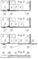
- a pulling device 17 is assigned to the gap thus formed, which the front row 2 of the layer 7 brought into its effective range subtracts from this and applies to the cross stop 12. The construction and the Operation of the puller 17 is described below with reference to FIGS. 2 to 6 explained in more detail.
- the pulling device 17 consists of a front peel plate 18 and a follower plate 19 attached to it.
- This plate arrangement bridges the gap between in each operating position the front end 16 of the receiving table 6 and the cross stop 12. Die mentioned plate arrangement is back and forth with a constant stroke in the feed direction movable, as indicated in Figures 3 to 5.
- a drive device 20 engages on the pull-off plate 18, the one constant stroke accomplished.
- the Drive device 20, as shown in FIG. 2 is designed as a crank drive, which with a crank pin 21 in one attached to the underside of the puller plate 18 Web 22 engages.
- the pull-off plate 18 and the follower plate 19 are, as FIG. 2 further shows, over at least one, preferably several, distributed over the plate width, the Butt joint of the plate arrangement bridging, hinged to the two plates Rod or rods 23 attached to each other.
- the linkages are as Ball joints formed
- the rod 23 is at its ends with calottes 24 provided in engagement with the underside of the pull-off plate 18 or Follower plate 19 attached ball heads 25 are.
- the rod 23 consists of a central part designed as a threaded sleeve, into which the spherical caps 24 load-bearing grub screws can be screwed in, so that the length can be adjusted exactly is. This ensures that the two plates can be adjusted exactly to each other are.
- the mutual articulation enables mutual shifts of the Plates perpendicular to the plane of the plate, which will be discussed in more detail below becomes.
- the peel plate 18 and the follower plate 19 are each assigned Guides 26 and 28 guided.
- the guide 26 assigned to the pull-off plate 18 runs parallel to the loading surface of the receiving table 6 and is arranged that the top of the pull-off plate 18 is always coplanar with the table level.
- For Formation of the table-parallel guides 26 of the pull-off plate 18 can be simple Rails are provided on which in the area of the underside of the pull-off plate 18, here on the web 22, attached barrel members 27, which here as on the associated rails attachable, cross-sectionally U-shaped rider are running.
- the guides 26 can be connected to the table 6 Substructure of the cross stop 12 may be attached.
- the guides 28 assigned to the follower plate 19 are in the form of a slide guide educated. For this purpose, each have a guide groove 29 Guide rails provided. With their rear end on Frame of the receiving table 7 be attached. Start in the guide grooves 29 the underside of the follower plate 19 attached, designed as rollers Running elements 30.
- the receiving table 6 is provided with a cantilever in the direction of the transverse stop 12, provided by a thin spring plate table projection 31. This lies with its front area on the follower plate 19.
- the front table edge 16 is the Pull-off plate 18 in the rear, on which FIGS. 2 and 3 are based End position employed, whereby due to the coplanar arrangement of Recording table 6 and pull-off plate 18 results in a flush transition.
- the Trailer plate 19 is in the rear end position under the Table projection 31 inserted.
- the follower plate 19 can be opposite submerge the pull-off plate 18 downwards.
- the guide grooves 29 have the Follower plate 19 associated link guide as can be seen from Figure 6, two adjoining sections 29a, b through a curve area 32 are interconnected, one of the thickness of the table protrusion 31st bridging corresponding height difference bridging.
- the front one Section 29a runs parallel to the loading surface of the receiving table 6 and is arranged so that the running elements 30 hereby engaged Trailer plate 19 in the course of the feed movement onto a loading surface of the recording table 6 raise the coplanar level.
- the rear section 29b is arranged with a slope to the rear so that the lower the table projection 31 retractable follower plate 19 with the table projection does not come into surface contact, as can be clearly seen in FIGS. 2 and 3 to let.
- the front runner 30 of the follower plate 19 the Driving over slope area 32
- the front area of the follower plate 19 raised or lowered which is due to the articulation of the Follower plate 19 on the pull-off plate 18 given degree of freedom of movement perpendicular to the plate plane is possible.
- the rear is also Area of the follower plate 19 raised or lowered accordingly.
- the peel plate 18 and the follower plate 19, such as can be seen from Figure 5, coplanar with each other and accordingly aligned coplanar to the table top of the loading table 7. Because of the As the follower plate 19 rises, the table projection 31 decreases by its thickness deflected above what the thin spring plate forming the table projection 31 readily possible.
- the front running members 30 of the follower plate 19 are, as from FIG. 2 can be clearly seen, arranged so that it is in the rear end position the plate assembly is positioned just at the lower end of curve area 32 are. This ensures that the front area of the follower plate 19 is raised at the start of the feed movement and vice versa.
- the stroke of the drive device 20 is smaller than that in the transport direction seen width of the follower plate 19, so that the table projection 31 also in the front end position of the plate arrangement still reliably on the rear Area of the follower plate 19 rests, as Figure 5 shows.
- the Stroke of the drive device 20 is greater than the difference between the distance the front table edge 16 of the cross stop 12 and that in Figure 5 at 2a indicated, assigned to the smallest format, in the direction of transport seen row width. This ensures that rows with the smallest format width reliably on the undercut by the peel plate 18 Cross stop 12 can be created.
- the row slide 13 can be moved sideways so far that the last packet 3a is inserted into the rocker 14, as can be seen in FIG. 1. Then the row slide 13 is again shown in FIG Starting position retracted.
- a rocker 14, Field 34 lying outside the rocker-side edge of layer 7 is cleared.
- This field 34 can be by means of a preferably non-contact scanning device be scanned.
- another application process can be started be initiated.
- the pulling device 17 is changed from that of FIG underlying front end position in the figures 2 and 3 underlying, rearward end position retracted, the above described movements take place in reverse, that is, where the Follower plate 19 from the level coplanar with the support table 6 below the Table projection 31 is lowered.
- the step between the pull-off plate in the rear end position 18 and the follower plate 19 can be removed by means of the ball plate 25 on the extractor plate side assigned washers 33 are balanced. That way achieved that the rod 23 in the rear end position parallel to the plate runs. In the course of the feed movement, the rod 23 becomes on the follower plate side tilted upwards, causing the formation of a gap between the pull-off plate 18 and counter plate 19 counteracts.
Landscapes
- Engineering & Computer Science (AREA)
- Mechanical Engineering (AREA)
- Sheets, Magazines, And Separation Thereof (AREA)
- Pile Receivers (AREA)
Abstract
Description
- Figur 1
- eine schematische Draufsicht auf einen erfindungsgemäßen Puffer einer Vorrichtung zur Herstellung von Etiketten,
- Figur 2
- einen Längsschnitt durch die Abzieheinrichtung der Anordnung gemäß Figur 1,
- Figuren 3-5
- mehrere Positionen der Abzieheinrichtung in Figur 2 entsprechender, schematisierter Darstellung und
- Figur 6
- eine Seitenansicht einer der Nachläuferplatte der Abzieheinrichtung zugeordneten Kulissenführung.
Claims (10)
- Vorrichtung zur Handhabung von Planschnittprodukten, insbesondere Puffer, der zwischen einer Planschnitteinrichtung (1) und einer Weiterverarbeitungseinrichtung (4) angeordnet ist, mit einem eine aus aufeinanderfolgenden Reihen (2) bestehende Lage (7) aufnehmenden Tisch (6), einer die Lage (7) schrittweise vorschiebenden Vorschubeinrichtung (10,11), einer die jeweils vorderste Reihe (2) der Lage (7) von dieser abziehenden und an einen quer zur Abziehrichtung verlaufenden Queranschlag (12) anlegenden Abzieheinrichtung (17) und einer dem Queranschlag (12) zugeordneten Räumeinrichtung (13) zum Austragen der an den Queranschlag angelegten Reihe (2), dadurch gekennzeichnet, dass zwischen dem Tisch (6) und dem Queranschlag (12) eine Lücke vorgesehen ist, in welcher sich die Abzieheinrichtung (17) befindet, die eine in und entgegen der Abziehrichtung bewegbare, aus einer vorderen, zum Tisch (6) koplanaren Abziehplatte (18) und einer an diese mit Bewegungsfreiheitsgrad senkrecht zur Tischebene angehängten Nachläuferplatte (19) bestehende Plattenanordnung aufweist, wobei die Abziehplatte (18) den Queranschlag (12) unterfährt und in der rückwärtigen Endstellung bündig an einen Tischvorsprung (31) anschließt und wobei die Nachläuferplatte (19), auf welcher der Tischvorsprung (31) aufliegt und die in der rückwärtigen Endstellung unter den Tischvorsprung (31) eingefahren ist, bei der Vorschubbewegung der Plattenanordnung zumindest mit ihrem vorderen Rand von ihrem unter Tischniveau liegenden Niveau auf ein mit der Abziehplatte (18) bündiges Niveau anhebbar ist und umgekehrt.
- Vorrichtung nach Anspruch 1, dadurch gekennzeichnet, dass die Abziehplatte (18) und Nachläuferplatte (19) mit im Bereich ihrer Unterseite vorgesehenen Lauforganen (27) bzw. (30) versehen sind, die im Eingriff mit zugeordneten Führungen (26) bzw. (28) sind, wobei die der Nachläuferplatte (19) zugeordneten Führungen (28) als mit einem Kurvenbereich (32) versehene Kulissenführung ausgebildet sind.
- Vorrichtung nach Anspruch 2, dadurch gekennzeichnet, dass die der Nachläuferplatte (19) zugeordnete Kulissenführung einen vorderen, tischparallelen Abschnitt (29a) und einen über den Kurvenbereich (32) hieran anschließenden, hinteren Abschnitt (29b) aufweist, der mit Gefälle zum hinteren Ende hin verläuft, wobei der Kurvenbereich (32) eine der Dicke des Tischvorsprungs (31) entsprechende Höhendifferenz überbrückt und die vorderen Lauforgane (30) der Nachläuferplatte (19) in der rückwärtigen Endstellung zumindest bis zum unteren Ende des Kurvenbereichs (32) gelangen.
- Vorrichtung nach einem der vorhergehenden Ansprüche 2 oder 3, dadurch gekennzeichnet, dass die vorzugsweise als Rollen ausgebildeten Lauforgane (30) der Nachläuferplatte (19) in eine die Kulissenführung bildende Führungsnut (29) mit den über den Kurvenbereich (32) aneinander anschließenden Abschnitten (29a,b) eingreifen.
- Vorrichtung nach einem der vorhergehenden Ansprüche 2 bis 4, dadurch gekennzeichnet, dass die Lauforgane (27) der Abziehplatte (18) als die jeweils zugeordnete, vorzugsweise als Schiene ausgebildete, tischparallele Führung (26) U-förmig umfassende Reiter ausgebildet sind.
- Vorrichtung nach einem der vorhergehenden Ansprüche, dadurch gekennzeichnet, dass der Tischvorsprung (31) als dünnes Federblech ausgebildet ist.
- Vorrichtung nach einem der vorhergehenden Ansprüche, dadurch gekennzeichnet, dass der Hub der aus Abziehplatte (18) und Nachläuferplatte (19) bestehenden Plattenanordnung konstant, vorzugsweise kleiner als die in Abziehrichtung gesehene Breite der Nachläuferplatte (19) und größer als die Differenz zwischen dem Abstand des Queranschlags (12) von der vorderen Tischkante (16) und der dem kleinsten Format (2a) zugeordneten Reihenbreite ist.
- Vorrichtung nach einem der vorhergehenden Ansprüche, dadurch gekennzeichnet, dass die Vorschubeinrichtung einen der Lage (7) zugeordneten Lagenschieber (11) aufweist, der bis zur rückwärtigen Tischkante (16) bewegbar ist.
- Vorrichtung nach einem der vorhergehenden Ansprüche, dadurch gekennzeichnet, dass die Abziehplatte (18) mit einer vorzugsweise als Kurbeltrieb ausgebildeten Antriebseinrichtung (20) verbunden ist.
- Vorrichtung nach einem der vorhergehenden Ansprüche, dadurch gekennzeichnet, dass die Abziehplatte (18) und die Nachläuferplatte (19) mittels wenigstens einer die Stoßfuge überbrückenden Stange (23), deren Länge vorzugsweise einstellbar ist, aneinander angehängt sind, die mit ihren Enden an beide Platten angelenkt ist, wobei die Stange (23) an ihren Enden mit Kugelkalotten (24) versehen ist, die im Eingriff mit an der Unterseite von Abziehplatte (18) bzw. Nachläuferplatte (19) angebrachten Kugelköpfen (25) sind und wobei jede abziehplattenseitige Kugelanordnung mittels eines Distanzelements (23), dessen Dicke der Dicke des Tischvorsprungs (31) entspricht, so positioniert ist, dass die Stange (23) in der rückwärtigen Endstellung tischparallel ist.
Applications Claiming Priority (2)
| Application Number | Priority Date | Filing Date | Title |
|---|---|---|---|
| DE1999126073 DE19926073C2 (de) | 1999-06-08 | 1999-06-08 | Vorrichtung zur Handhabung von Planschnittprodukten |
| DE19926073 | 1999-06-08 |
Publications (2)
| Publication Number | Publication Date |
|---|---|
| EP1061018A1 true EP1061018A1 (de) | 2000-12-20 |
| EP1061018B1 EP1061018B1 (de) | 2003-07-23 |
Family
ID=7910536
Family Applications (1)
| Application Number | Title | Priority Date | Filing Date |
|---|---|---|---|
| EP20000111328 Expired - Lifetime EP1061018B1 (de) | 1999-06-08 | 2000-05-26 | Vorrichtung zur Handhabung von Planschnittprodukten |
Country Status (3)
| Country | Link |
|---|---|
| US (1) | US6334524B1 (de) |
| EP (1) | EP1061018B1 (de) |
| DE (2) | DE19926073C2 (de) |
Cited By (2)
| Publication number | Priority date | Publication date | Assignee | Title |
|---|---|---|---|---|
| CN102133986A (zh) * | 2011-01-26 | 2011-07-27 | 山东兰剑物流科技有限公司 | 一种集成化烟草物流仓库及其仓储方法 |
| EP2436623A1 (de) | 2010-10-04 | 2012-04-04 | Adolf Mohr Maschinenfabrik GmbH & Co. KG | Verfahren und Vorrichtung zum Abfördern einer Stapelreihe |
Families Citing this family (1)
| Publication number | Priority date | Publication date | Assignee | Title |
|---|---|---|---|---|
| CN105129361B (zh) * | 2015-10-08 | 2018-03-06 | 山东兰剑物流科技股份有限公司 | 一种料箱自动存取系统缓存装置 |
Citations (2)
| Publication number | Priority date | Publication date | Assignee | Title |
|---|---|---|---|---|
| US4610347A (en) * | 1984-09-03 | 1986-09-09 | Tetra Pak International Aktiebolag | Dividing device for collecting commodities incorporated in a commodity collecting device |
| US5267821A (en) * | 1992-02-28 | 1993-12-07 | R. R. Donnelley & Sons Co. | Bindery line book accumulator |
Family Cites Families (2)
| Publication number | Priority date | Publication date | Assignee | Title |
|---|---|---|---|---|
| DE3613315A1 (de) * | 1986-04-19 | 1987-10-22 | Wolfgang Mohr | Anordnung zum zufuehren von gestapeltem, blattfoermigen gut zu einer weiterverarbeitungsstation, insbesondere schneidstation |
| US5960927A (en) * | 1997-04-30 | 1999-10-05 | Mgs Machine Corporation | Apparatus for providing a buffer between article-handling devices |
-
1999
- 1999-06-08 DE DE1999126073 patent/DE19926073C2/de not_active Expired - Fee Related
-
2000
- 2000-05-15 US US09/571,404 patent/US6334524B1/en not_active Expired - Lifetime
- 2000-05-26 DE DE50002966T patent/DE50002966D1/de not_active Expired - Lifetime
- 2000-05-26 EP EP20000111328 patent/EP1061018B1/de not_active Expired - Lifetime
Patent Citations (2)
| Publication number | Priority date | Publication date | Assignee | Title |
|---|---|---|---|---|
| US4610347A (en) * | 1984-09-03 | 1986-09-09 | Tetra Pak International Aktiebolag | Dividing device for collecting commodities incorporated in a commodity collecting device |
| US5267821A (en) * | 1992-02-28 | 1993-12-07 | R. R. Donnelley & Sons Co. | Bindery line book accumulator |
Cited By (3)
| Publication number | Priority date | Publication date | Assignee | Title |
|---|---|---|---|---|
| EP2436623A1 (de) | 2010-10-04 | 2012-04-04 | Adolf Mohr Maschinenfabrik GmbH & Co. KG | Verfahren und Vorrichtung zum Abfördern einer Stapelreihe |
| CN102133986A (zh) * | 2011-01-26 | 2011-07-27 | 山东兰剑物流科技有限公司 | 一种集成化烟草物流仓库及其仓储方法 |
| CN102133986B (zh) * | 2011-01-26 | 2012-08-22 | 山东兰剑物流科技有限公司 | 一种集成化烟草物流仓库及其仓储方法 |
Also Published As
| Publication number | Publication date |
|---|---|
| DE19926073C2 (de) | 2001-05-10 |
| DE19926073A1 (de) | 2001-01-25 |
| EP1061018B1 (de) | 2003-07-23 |
| US6334524B1 (en) | 2002-01-01 |
| DE50002966D1 (de) | 2003-08-28 |
Similar Documents
| Publication | Publication Date | Title |
|---|---|---|
| DE3613316C1 (de) | Vorrichtung zum Schneiden von gestapeltem,blattfoermigem Gut | |
| DE3122451A1 (de) | Verfahren und vorrichtung zum stapeln von materialblaettern | |
| DE2125991A1 (de) | Verfahren und Vorrichtung zum Transport gestapelter flacher Gegenstände in Aufeinanderfolge zu einem Auffangen | |
| DE3613315C2 (de) | ||
| DE3217038A1 (de) | Verfahren und vorrichtung zum stanzschneiden von bahn- oder plattenfoermigem schneidgut | |
| DE4008592A1 (de) | Vorrichtung zum automatischen Zu- und Abführen von Platten aus Karton, Wellpappe und dergl., zu einer Stanz- und/oder Druckmaschine | |
| DE4411597A1 (de) | Blattanleger | |
| DE1959174A1 (de) | Vorrichtung zum Stapeln,Ausrichten und Abgeben von Kartonzuschnitten aus Wellpappe | |
| DE3318314C2 (de) | Vorrichtung zum Trennen einzelner Nutzenstapel eines Stapels gestanzter Bögen | |
| DE10009672A1 (de) | Waffelblockschneider | |
| DE3409178C2 (de) | Einrichtung zum Zusammensetzen und Verbinden von flächigen Werkstücken | |
| EP1061018B1 (de) | Vorrichtung zur Handhabung von Planschnittprodukten | |
| DE4244089C2 (de) | Vorrichtung zur automatischen Stapelung von konkaven Gegenständen, wie Schalen, Teller, Becher o. dgl. aus Kunststoff oder Papier | |
| DE3783057T2 (de) | Apparat zum zufuehren von karton. | |
| EP2468636B1 (de) | Vorrichtung zur Bildung von Zigarettengruppen | |
| DE2913786C3 (de) | Eingabetisch | |
| DE4041553C2 (de) | Verfahren und Einrichtung zum kontinuierlichen Preßverleimen von Leisten | |
| DE2920667A1 (de) | Verfahren und vorrichtung zum stapeln von quaderfoermigen produkten, insbesondere von quaderfoermigen druckerzeugnissen, zeitschriften o.dgl. | |
| DE2062370A1 (de) | Vorrichtung zum Ablegen von blattförmigen Werkstücken | |
| DE3317522C2 (de) | Einschubvorrichtung für eine Durchlauffugenverleimpresse | |
| DE4430701A1 (de) | Verfahren zur Entnahme einer Faltschachtel aus einem Abgabeschacht sowie Lagervorrichtung für Faltschachteln | |
| EP0037392A2 (de) | Vorrichtung zum Zuführen von Querstäben zu einer Gitterschweissmaschine | |
| EP2436623B1 (de) | Verfahren und Vorrichtung zum Abfördern einer Stapelreihe | |
| CH628592A5 (en) | Sheet dispenser and container for this sheet dispenser | |
| EP1577243B1 (de) | Vorrichtung zum Zuführen eines Stapels zu einer Weiterverarbeitungsstation |
Legal Events
| Date | Code | Title | Description |
|---|---|---|---|
| PUAI | Public reference made under article 153(3) epc to a published international application that has entered the european phase |
Free format text: ORIGINAL CODE: 0009012 |
|
| AK | Designated contracting states |
Kind code of ref document: A1 Designated state(s): AT BE CH LI |
|
| AX | Request for extension of the european patent |
Free format text: AL;LT;LV;MK;RO;SI |
|
| 17P | Request for examination filed |
Effective date: 20010529 |
|
| AKX | Designation fees paid |
Free format text: AT BE CH LI |
|
| RBV | Designated contracting states (corrected) |
Designated state(s): CH DE IT LI |
|
| 17Q | First examination report despatched |
Effective date: 20020301 |
|
| GRAH | Despatch of communication of intention to grant a patent |
Free format text: ORIGINAL CODE: EPIDOS IGRA |
|
| GRAH | Despatch of communication of intention to grant a patent |
Free format text: ORIGINAL CODE: EPIDOS IGRA |
|
| GRAA | (expected) grant |
Free format text: ORIGINAL CODE: 0009210 |
|
| RAP1 | Party data changed (applicant data changed or rights of an application transferred) |
Owner name: ADOLF MOHR MASCHINENFABRIK GMBH & CO. KG |
|
| AK | Designated contracting states |
Designated state(s): CH DE IT LI |
|
| REG | Reference to a national code |
Ref country code: CH Ref legal event code: EP |
|
| REF | Corresponds to: |
Ref document number: 50002966 Country of ref document: DE Date of ref document: 20030828 Kind code of ref document: P |
|
| REG | Reference to a national code |
Ref country code: CH Ref legal event code: NV Representative=s name: ISLER & PEDRAZZINI AG |
|
| PLBE | No opposition filed within time limit |
Free format text: ORIGINAL CODE: 0009261 |
|
| STAA | Information on the status of an ep patent application or granted ep patent |
Free format text: STATUS: NO OPPOSITION FILED WITHIN TIME LIMIT |
|
| 26N | No opposition filed |
Effective date: 20040426 |
|
| REG | Reference to a national code |
Ref country code: CH Ref legal event code: PCAR Free format text: ISLER & PEDRAZZINI AG;POSTFACH 1772;8027 ZUERICH (CH) |
|
| PGFP | Annual fee paid to national office [announced via postgrant information from national office to epo] |
Ref country code: IT Payment date: 20100522 Year of fee payment: 11 |
|
| PG25 | Lapsed in a contracting state [announced via postgrant information from national office to epo] |
Ref country code: IT Free format text: LAPSE BECAUSE OF NON-PAYMENT OF DUE FEES Effective date: 20110526 |
|
| PGFP | Annual fee paid to national office [announced via postgrant information from national office to epo] |
Ref country code: CH Payment date: 20140521 Year of fee payment: 15 |
|
| PGFP | Annual fee paid to national office [announced via postgrant information from national office to epo] |
Ref country code: DE Payment date: 20140718 Year of fee payment: 15 |
|
| REG | Reference to a national code |
Ref country code: DE Ref legal event code: R119 Ref document number: 50002966 Country of ref document: DE |
|
| REG | Reference to a national code |
Ref country code: CH Ref legal event code: PL |
|
| PG25 | Lapsed in a contracting state [announced via postgrant information from national office to epo] |
Ref country code: CH Free format text: LAPSE BECAUSE OF NON-PAYMENT OF DUE FEES Effective date: 20150531 Ref country code: LI Free format text: LAPSE BECAUSE OF NON-PAYMENT OF DUE FEES Effective date: 20150531 |
|
| PG25 | Lapsed in a contracting state [announced via postgrant information from national office to epo] |
Ref country code: DE Free format text: LAPSE BECAUSE OF NON-PAYMENT OF DUE FEES Effective date: 20151201 |