EP1061190A1 - Sound insulating sandwich element - Google Patents
Sound insulating sandwich element Download PDFInfo
- Publication number
- EP1061190A1 EP1061190A1 EP99111191A EP99111191A EP1061190A1 EP 1061190 A1 EP1061190 A1 EP 1061190A1 EP 99111191 A EP99111191 A EP 99111191A EP 99111191 A EP99111191 A EP 99111191A EP 1061190 A1 EP1061190 A1 EP 1061190A1
- Authority
- EP
- European Patent Office
- Prior art keywords
- core
- layers
- element according
- contact points
- facing
- Prior art date
- Legal status (The legal status is an assumption and is not a legal conclusion. Google has not performed a legal analysis and makes no representation as to the accuracy of the status listed.)
- Granted
Links
- 239000012792 core layer Substances 0.000 claims abstract description 71
- 239000010410 layer Substances 0.000 claims abstract description 55
- 239000000463 material Substances 0.000 claims abstract description 27
- 238000005192 partition Methods 0.000 claims abstract description 24
- 238000010276 construction Methods 0.000 claims abstract description 19
- 239000002984 plastic foam Substances 0.000 claims abstract description 14
- 230000001413 cellular effect Effects 0.000 claims abstract description 4
- 239000011162 core material Substances 0.000 claims description 45
- 239000006260 foam Substances 0.000 claims description 21
- 239000002184 metal Substances 0.000 claims description 13
- 229910052751 metal Inorganic materials 0.000 claims description 13
- 229910000831 Steel Inorganic materials 0.000 claims description 9
- 229920003023 plastic Polymers 0.000 claims description 9
- 239000004033 plastic Substances 0.000 claims description 9
- 239000010959 steel Substances 0.000 claims description 9
- 239000002023 wood Substances 0.000 claims description 9
- 229920005830 Polyurethane Foam Polymers 0.000 claims description 8
- 238000000034 method Methods 0.000 claims description 8
- 239000011496 polyurethane foam Substances 0.000 claims description 8
- 238000004519 manufacturing process Methods 0.000 claims description 6
- 239000011449 brick Substances 0.000 claims description 5
- 238000005304 joining Methods 0.000 claims description 5
- 239000004411 aluminium Substances 0.000 claims description 4
- 229910052782 aluminium Inorganic materials 0.000 claims description 4
- XAGFODPZIPBFFR-UHFFFAOYSA-N aluminium Chemical compound [Al] XAGFODPZIPBFFR-UHFFFAOYSA-N 0.000 claims description 4
- 239000011507 gypsum plaster Substances 0.000 claims description 3
- 239000004927 clay Substances 0.000 claims description 2
- 238000005520 cutting process Methods 0.000 claims description 2
- 238000003754 machining Methods 0.000 claims description 2
- 239000004575 stone Substances 0.000 claims 1
- 238000009413 insulation Methods 0.000 description 18
- 239000004814 polyurethane Substances 0.000 description 8
- 229920002635 polyurethane Polymers 0.000 description 7
- 239000000853 adhesive Substances 0.000 description 6
- 230000001070 adhesive effect Effects 0.000 description 6
- 239000011093 chipboard Substances 0.000 description 6
- 230000000694 effects Effects 0.000 description 6
- 239000002557 mineral fiber Substances 0.000 description 6
- 239000011094 fiberboard Substances 0.000 description 5
- -1 acryl Chemical group 0.000 description 4
- 239000003292 glue Substances 0.000 description 4
- 239000011490 mineral wool Substances 0.000 description 4
- 229920001084 poly(chloroprene) Polymers 0.000 description 4
- 239000004821 Contact adhesive Substances 0.000 description 3
- 239000004698 Polyethylene Substances 0.000 description 3
- 238000004026 adhesive bonding Methods 0.000 description 3
- 239000010440 gypsum Substances 0.000 description 3
- 229910052602 gypsum Inorganic materials 0.000 description 3
- 239000012774 insulation material Substances 0.000 description 3
- 239000004570 mortar (masonry) Substances 0.000 description 3
- 239000011120 plywood Substances 0.000 description 3
- 239000004793 Polystyrene Substances 0.000 description 2
- 230000005540 biological transmission Effects 0.000 description 2
- 239000011796 hollow space material Substances 0.000 description 2
- 238000009434 installation Methods 0.000 description 2
- 229920000573 polyethylene Polymers 0.000 description 2
- 229920002223 polystyrene Polymers 0.000 description 2
- 239000004800 polyvinyl chloride Substances 0.000 description 2
- 229920000915 polyvinyl chloride Polymers 0.000 description 2
- 230000002787 reinforcement Effects 0.000 description 2
- 230000003014 reinforcing effect Effects 0.000 description 2
- 235000008331 Pinus X rigitaeda Nutrition 0.000 description 1
- 235000011613 Pinus brutia Nutrition 0.000 description 1
- 241000018646 Pinus brutia Species 0.000 description 1
- 238000010521 absorption reaction Methods 0.000 description 1
- 230000001154 acute effect Effects 0.000 description 1
- 239000010426 asphalt Substances 0.000 description 1
- 230000000712 assembly Effects 0.000 description 1
- 238000000429 assembly Methods 0.000 description 1
- 230000009286 beneficial effect Effects 0.000 description 1
- 239000011111 cardboard Substances 0.000 description 1
- 239000004567 concrete Substances 0.000 description 1
- 238000013016 damping Methods 0.000 description 1
- 230000001627 detrimental effect Effects 0.000 description 1
- 239000000835 fiber Substances 0.000 description 1
- 229920002457 flexible plastic Polymers 0.000 description 1
- 239000006261 foam material Substances 0.000 description 1
- 239000011888 foil Substances 0.000 description 1
- 239000011491 glass wool Substances 0.000 description 1
- 239000011464 hollow brick Substances 0.000 description 1
- 239000011810 insulating material Substances 0.000 description 1
- 239000011133 lead Substances 0.000 description 1
- 239000000203 mixture Substances 0.000 description 1
- 239000011087 paperboard Substances 0.000 description 1
- 239000002245 particle Substances 0.000 description 1
- 239000011505 plaster Substances 0.000 description 1
- 239000002985 plastic film Substances 0.000 description 1
- 239000011148 porous material Substances 0.000 description 1
- 238000002360 preparation method Methods 0.000 description 1
- 230000005855 radiation Effects 0.000 description 1
- 238000009877 rendering Methods 0.000 description 1
- 239000007787 solid Substances 0.000 description 1
- 239000007921 spray Substances 0.000 description 1
- 229920003002 synthetic resin Polymers 0.000 description 1
- 239000000057 synthetic resin Substances 0.000 description 1
- 239000002937 thermal insulation foam Substances 0.000 description 1
Images


Classifications
-
- E—FIXED CONSTRUCTIONS
- E04—BUILDING
- E04B—GENERAL BUILDING CONSTRUCTIONS; WALLS, e.g. PARTITIONS; ROOFS; FLOORS; CEILINGS; INSULATION OR OTHER PROTECTION OF BUILDINGS
- E04B9/00—Ceilings; Construction of ceilings, e.g. false ceilings; Ceiling construction with regard to insulation
- E04B9/04—Ceilings; Construction of ceilings, e.g. false ceilings; Ceiling construction with regard to insulation comprising slabs, panels, sheets or the like
- E04B9/045—Ceilings; Construction of ceilings, e.g. false ceilings; Ceiling construction with regard to insulation comprising slabs, panels, sheets or the like being laminated
-
- E—FIXED CONSTRUCTIONS
- E04—BUILDING
- E04B—GENERAL BUILDING CONSTRUCTIONS; WALLS, e.g. PARTITIONS; ROOFS; FLOORS; CEILINGS; INSULATION OR OTHER PROTECTION OF BUILDINGS
- E04B1/00—Constructions in general; Structures which are not restricted either to walls, e.g. partitions, or floors or ceilings or roofs
- E04B1/62—Insulation or other protection; Elements or use of specified material therefor
- E04B1/74—Heat, sound or noise insulation, absorption, or reflection; Other building methods affording favourable thermal or acoustical conditions, e.g. accumulating of heat within walls
- E04B1/82—Heat, sound or noise insulation, absorption, or reflection; Other building methods affording favourable thermal or acoustical conditions, e.g. accumulating of heat within walls specifically with respect to sound only
- E04B1/84—Sound-absorbing elements
- E04B1/86—Sound-absorbing elements slab-shaped
-
- E—FIXED CONSTRUCTIONS
- E04—BUILDING
- E04B—GENERAL BUILDING CONSTRUCTIONS; WALLS, e.g. PARTITIONS; ROOFS; FLOORS; CEILINGS; INSULATION OR OTHER PROTECTION OF BUILDINGS
- E04B1/00—Constructions in general; Structures which are not restricted either to walls, e.g. partitions, or floors or ceilings or roofs
- E04B1/62—Insulation or other protection; Elements or use of specified material therefor
- E04B1/74—Heat, sound or noise insulation, absorption, or reflection; Other building methods affording favourable thermal or acoustical conditions, e.g. accumulating of heat within walls
- E04B1/82—Heat, sound or noise insulation, absorption, or reflection; Other building methods affording favourable thermal or acoustical conditions, e.g. accumulating of heat within walls specifically with respect to sound only
- E04B1/84—Sound-absorbing elements
- E04B2001/8423—Tray or frame type panels or blocks, with or without acoustical filling
- E04B2001/8442—Tray type elements
- E04B2001/8447—Tray type elements with two facing trays
-
- E—FIXED CONSTRUCTIONS
- E04—BUILDING
- E04B—GENERAL BUILDING CONSTRUCTIONS; WALLS, e.g. PARTITIONS; ROOFS; FLOORS; CEILINGS; INSULATION OR OTHER PROTECTION OF BUILDINGS
- E04B1/00—Constructions in general; Structures which are not restricted either to walls, e.g. partitions, or floors or ceilings or roofs
- E04B1/62—Insulation or other protection; Elements or use of specified material therefor
- E04B1/74—Heat, sound or noise insulation, absorption, or reflection; Other building methods affording favourable thermal or acoustical conditions, e.g. accumulating of heat within walls
- E04B1/82—Heat, sound or noise insulation, absorption, or reflection; Other building methods affording favourable thermal or acoustical conditions, e.g. accumulating of heat within walls specifically with respect to sound only
- E04B1/84—Sound-absorbing elements
- E04B2001/8423—Tray or frame type panels or blocks, with or without acoustical filling
- E04B2001/8452—Tray or frame type panels or blocks, with or without acoustical filling with peripheral frame members
-
- E—FIXED CONSTRUCTIONS
- E04—BUILDING
- E04B—GENERAL BUILDING CONSTRUCTIONS; WALLS, e.g. PARTITIONS; ROOFS; FLOORS; CEILINGS; INSULATION OR OTHER PROTECTION OF BUILDINGS
- E04B1/00—Constructions in general; Structures which are not restricted either to walls, e.g. partitions, or floors or ceilings or roofs
- E04B1/62—Insulation or other protection; Elements or use of specified material therefor
- E04B1/74—Heat, sound or noise insulation, absorption, or reflection; Other building methods affording favourable thermal or acoustical conditions, e.g. accumulating of heat within walls
- E04B1/82—Heat, sound or noise insulation, absorption, or reflection; Other building methods affording favourable thermal or acoustical conditions, e.g. accumulating of heat within walls specifically with respect to sound only
- E04B1/84—Sound-absorbing elements
- E04B2001/8457—Solid slabs or blocks
- E04B2001/8461—Solid slabs or blocks layered
-
- E—FIXED CONSTRUCTIONS
- E04—BUILDING
- E04B—GENERAL BUILDING CONSTRUCTIONS; WALLS, e.g. PARTITIONS; ROOFS; FLOORS; CEILINGS; INSULATION OR OTHER PROTECTION OF BUILDINGS
- E04B1/00—Constructions in general; Structures which are not restricted either to walls, e.g. partitions, or floors or ceilings or roofs
- E04B1/62—Insulation or other protection; Elements or use of specified material therefor
- E04B1/74—Heat, sound or noise insulation, absorption, or reflection; Other building methods affording favourable thermal or acoustical conditions, e.g. accumulating of heat within walls
- E04B1/82—Heat, sound or noise insulation, absorption, or reflection; Other building methods affording favourable thermal or acoustical conditions, e.g. accumulating of heat within walls specifically with respect to sound only
- E04B1/84—Sound-absorbing elements
- E04B2001/8457—Solid slabs or blocks
- E04B2001/8476—Solid slabs or blocks with acoustical cavities, with or without acoustical filling
Definitions
- the present invention refers to sound insulating sandwich elements, more specifically to sound insulating multilayered building or construction elements or components such as doors, partitions, walls or ceilings comprising an open-cell, semi-rigid foam core consisting of at least one core material, and comprising one or more than one hollow space or air gap located within the core, and comprising two outer facing layers. More specifically the invention refers to sound insulating sandwich elements, such as doors, partition elements, walls, ceilings, floors, bulkheads, fire doors, traps, lids, flaps, windows, compartment elements, or panels in new or existing buildings.
- the new sandwich elements are useful in buildings, in the construction industry, or other industries in order to improve the sound insulation performance.
- the invention refers to sound insulating elements excelling prior art elements in constructional simplicity, mechanical strength, and rigidity and to the use of such new, sound insulating, multilayered sandwich elements in the construction or other industries for acoustically improving walls, partitions, ceilings, and other parts of the building, structure or machinery.
- panels as partition walls in order to subdivide the building area into seperate areas such as rooms and offices.
- they consist of an insulating mineral fiber core and two outer facing layers encompassing the core and an air gap or hollow space.
- the insulating materials such as mineral fibers are arranged between the facing layers in such a manner so as to provide thermal and/or acoustic insulation.
- a noise insulating panel in which a porous material, such as glass wool or foamed synthetic resin is stacked between facing layers formed by plywood, gypsum board, or an acryl plate in such a manner as to be out of contact with at least one surface material.
- a frame must be used in order to stabilize or fix this condition. This frame is fitted to the above assembly to form a panel. This, of course, is a relatively intricate and hence expensive procedure. Furthermore, it is a well known method extrapolated from conventional timber frame walls or panels.
- DE 3710 057 discloses a multilayered acoustic insulation panel for internal walls which has air gaps between a layer of mineral wool and an outer chipboard facing layer.
- This insulation panel contains a main panel made of chipboard which is spaced apart by ribs from a facing layer or cover panel which is also made of chipboard. The inner surfaces of these two panels are covered with fiber board which is held in place by glue. For attaining good sound dampening performance the two fiber boards are different in weight.
- This multilayered panel consists of five layers, i. e. two chipboard layers, each of which is glued to a fiber board, plus a mineral wool layer in the middle of the sandwich serving as acoustic insulation material.
- the mineral wool fills the space only partly in such a way that an air gap is provided for between the mineral wool and one of the fiber boards which is glued to the inner surface of the cover panel. The latter is secured by screws to the ribs.
- the design of this multilayered panel is quite complicated. Its fabrication is therefore relatively expensive. The acoustic performance is achieved by increasing the mass rendering such panels difficult to transport and to install.
- organic plastics have been used instead of mineral fibers, such as, for example, the well-known open-cell polyurethane foam laminates.
- such laminates exhibit the disadvantage of being brittle and having a poor tensile strength (about 30 kPa).
- a sound insulating building element which includes a plurality of parallel layer elements of which a first inner, thick element is constituted by a layer of mineral fibers or stiff plastic foam and contains a plurality of cavities.
- a second inner stiff element which is substantially pervious to air is connected to one main surface of the first inner element and an outer impervious element.
- the outer impervious element is arranged at a small distance from the second inner element in such a manner that substantially the entire outer element can oscillate freely in relation to the second inner element.
- partitions are the multilayered structures including those having a foam or honeycomb core.
- the foam cores although possessing suitable mechanical strength properties, are very poor as far as the sound insulating properties are concerned. In order to overcome this problem, the foam core would have to be of an unacceptable thickness and weight.
- Those multilayered insulating panels or elements comprise in a preferred embodiment (a) two outer facing layers, and (b) a soft synthetic core material which is a single, continuous, soft, synthetic foam core layer having cavities and being arranged in intimate contact with both outer layers through contact points in alternate patterns, thereby providing gaps between the core layer and the opposing outer layer.
- Panels as disclosed in WO 95/14 136 possess both acoustic insulating properties and mechanical strength. While this art provides lighter and cheaper panels with good acoustic properties compared to previously known products, it was still highly desirable to provide room partition elements and sandwich elements such as doors, and partitions having both sound insulating properties and good mechanical strength, which would be particularly useful for up-grading residential and office buildings and for designing partitions with improved sound insulation performance. Also, there was a need for more economical methods for producing and installing such sound insulating panels.
- the previous European Patent Application 98 111 295.6 - 2303 (Dow Case 44,161) is directed to a multilayered, sound insulating panel comprising a facing layer, a plastic foam core layer attached thereto wherein the core layer material is a semi-rigid, cellular material having certain characteristics, a structure, to which the core layer is fixed at seperated contact points by means of stripes, patches, dabs, or other geometrical protrusions (generally called "contact points") leaving gaps between the core layer and the structure, and, in case of long spans and/or thin facing layers, travel stops to keep the core layer at a certain distance from the structure.
- contact points geometrical protrusions
- the panels according to EU 98 111 295.6 - 2303 are useful in the construction and other industries for improving the sound insulating properties of buildings and/or machinery.
- sandwich elements are in general suitable as partition elements their mechanical strength may not be sufficient due to the presence of the large gap between the facing and the core in application fields where strength and resistance are of particular importance to the applicability of a construction element, such as in the construction of doors or walls.
- the present invention provides a multilayered, sound insulating sandwich element comprising facing layers and a plastic foam core located between the facing layers and attached to the facing layers, the core presenting one ore more than one cavities, which sound insulating element is characterized in that
- the distance between the contact points is preferably at least 350 mm, more preferred is a minimum of 450 mm, or even 600 mm as long as mechanical integrity can be preserved.
- the facing layers may have a thickness, each, from 0.5 to 100 mm, preferably from 0.5 to 25 mm.
- the facing layer material can be a 0.5 to 20 mm thick metal sheet, preferably steel or aluminium, or a 4 to 25 mm thick wood sheet. Other materials, useful in a specific application field, can be selected by the expert in the art.
- the foam core layer may have a thickness from 20 to 500 mm, preferably from 20 to 300 mm and even more preferred up to 200 mm.
- Each foam core layer has in general a minimal thickness of 10 mm to achieve significant dampening, preferably a thickness from 15 to 100 mm. It should be noted, however, that these ranges should not be construed as being restrictive. Values outside these ranges may be suited for particular applications, e. g. establishments requiring a very high sound dampening performance.
- the foam core layers may have or not the same thickness. In some cases of facing materials it has been found beneficial to use different thicknesses so as to minimize the negative effect of the characteristic critical frequencies of the assembly made from the facing and the core layers.
- the core layer material is a polyurethane foam, for instance of the type whose preparation is disclosed in US Patent No. 5,538,779.
- the core layer material can comprise more than one foam type.
- it may include in addition to polyurethane, polyethylene or polystyrene. It may also comprise bitumen or heavy plastic or sheets made of other materials.
- the core layer material has an air flow resistivity from 5 000 to 800 000 Ns/m4, preferably from 5 000 to 300 000 Ns/m4.
- the loss factor of the core layer material is preferably greater than 0.1, preferably greater than 0.2 (as defined by SAE Sound and Heat Insulation Materials Committee, SAE Handbook, 1994, Volume 1, page 2.30); the loss factor can reach 0.3, or even more.
- travel stops are provided at at least one of the core layers and within the gap in order to make sure that the core layers are always kept at a certain distance from each other.
- the distance of the travel stops from the opposite core layer or the distance of the core layers from each other, at 0 % deformation, is preferably at least 0.1 mm, and preferred ranges are between 2 and 10 mm.
- the total contact points area is related to the total area of the sandwich element in a ratio of less than 30 %, preferably less than 15 %.
- the contact points are plastic foam, plastic, metal or wood stripes of a thickness of from 0.5 to 100 mm and a width from 10 to 100 mm. These ranges should, however, not be construed as being restrictive and may vary depending upon the specific stress requirement of the application and the stiffness of the facings. Very rigid facings would for instance allow an air gap of unspecified thickness. Protruding parts of the core layers or even other constructional elements, such as door frames, may assume the function of the contact points or "bridges".
- the present invention provides a process for the fabrication of the new sound insulating sandwich element by attaching the facing layers to the plastic foam core which process is characterized in that the plastic foam core is produced by joining two core layers through contact points or bridges at predetermined distances thus leaving a gap or gaps between the core layers or by first machining two core layers in such a way that contact points or bridges are formed at predetermined distances as integral parts of the core layers and by joining the two core layers afterwards through the contact points or bridges leaving a gap or gaps between the core layers or by cutting out the gap or gaps from a single plastic foam board.
- the present invention provides the use of the new sound insulating sandwich element in the construction and other industries for improving the sound insulating properties of buildings and/or machinery.
- a particularly surprising feature of the invention is that long span vibration of the core layer attached to the facing layer provides particularly good dampening at all frequencies and specifically at the resonant and the critical frequencies.
- the gaps created within the foam core can vary considerably depending on the actual needs in a given case. Very rigid facings would allow an air gap of unspecified thickness.
- the thickness usually ranges from 0.1 to 200 mm. Sometimes the thickness is selected between 20 and 50 mm so as to allow for passing cables, pipes and other service lines. Apart from those special consideration, the thickness of the gaps is often in the range from 1 to 10 mm, preferably from 2 to 5 mm.
- a "mid span" travel stop system made of a stripe or patches can be installed to limit the plasterboard deformation.
- a travel stop stripe will be fixed in the middle of the board in order to reduce the span.
- the width of the travel stop stripe will be between 30 and 39.9 mm, preferably between 35 and 38 mm, if the contact stripe width is e. g. 40 mm.
- Typical reinforcements will be wood or metal frames for the door application, steel studs or beams between panels for the partition application, and mortar or glue for wall application.
- the facing layers can be made of any material typically employed to produce insulating sandwich elements or panels.
- Exemplary materials useful as facing layers include plastic or particle boards, thick paper or cardboards, fiber boards, gypsum plaster boards, flexible plastic films or foils, metal sheets, such as steel, lead, or aluminium sheets, plywood, timber boards, and chipboards, most typical being gypsum plaster boards, and chipboards.
- the preferred material for use as facing layer is gypsum board in the partition applications and metal sheet or wood boards in the door applications.
- a core layer made of polyurethane foam and having seperated polyurethane foam patches as contact points at one of its two surfaces is substantially attached by means of adhesives at its "inner" surface to another polyurethane foam core layer, thus forming a core.
- adhesives at its "inner" surface to another polyurethane foam core layer, thus forming a core.
- a panel will be prefabricated thereby avoiding assembling on site.
- the core will then be fixed to the two facing layers, usually by glueing with a suitable adhesive such as polyurethane glue, neoprene contact or transfer adhesive, or by mechanical fixing in order to produce a sandwich element according to the invention.
- the sandwich element thus obtained can be used for instance as doors.
- the facing material for doors usually are thin layers of metal sheet or wood sheets and are substantially attached to the core layers in order to fulfill requirements such as heat stability, impact deformation resistance, perfectly plane surface and aesthetics. It is therefore important that no gaps are created between the reinforcing foam core and the facing layers when the latter lack stiffness.
- the new sandwich element can also be used for instance as a room partition standing on its own.
- a partition element is usually secured on the floor and/or at the ceiling. It can be fixed to a wall, ceiling, floor, or other building structure.
- the sandwich partition concept as per the invention concerns space dividing units, mostly for offices, industry cabins and other panel applications where the combination of lightweight, easy connecting devices, handability and sound insulation performance are important requirements.
- These partitions may rest in vertical or horizontal positions but, in some embodiments, they may as well be positioned at acute or obtuse angles.
- the contact points can be machined from the polyurethane foam layer or can be made from other suitable materials, such as plastics other than polyurethane, glue or other adhesives; wood, plaster, metal etc., as long as the inventive criteria are fulfilled.
- the new sandwich elements function like brickstones in a building wall, a ceiling, a floor or any other construction part or unit.
- the new sound insulating sandwich elements are particularly useful for refurbishing existing buildings, but also as elements in new constructions. They can be manufactured as doors or partition elements or wall construction units. They offer a thin, light weight and mechanically strong solution to improve sound insulation, thus eliminating or damping sounds and noises which without the sound insulating elements are transmitted through walls, doors, floors, ceilings and partitions.
- the sandwich elements according to the invention are to a surprising degree substantially superior as compared to prior art sound insulating elements with respect to a combination of sound insulation/ mechanical strength/ light weight/thickness properties and production/ installation methods. They excel in mechanical strength as compared to sound insulating sandwich elements of the state of the art, possess a high acoustic dampening performance, reduce and lower the resonant frequency.
- the gap within the core is acting as a first very soft spring, and the core layers are acting as second hard springs. Because of the hardness of the core layers, the deformation of the element is strongly restricted which makes it compatible with the intended use in buildings.
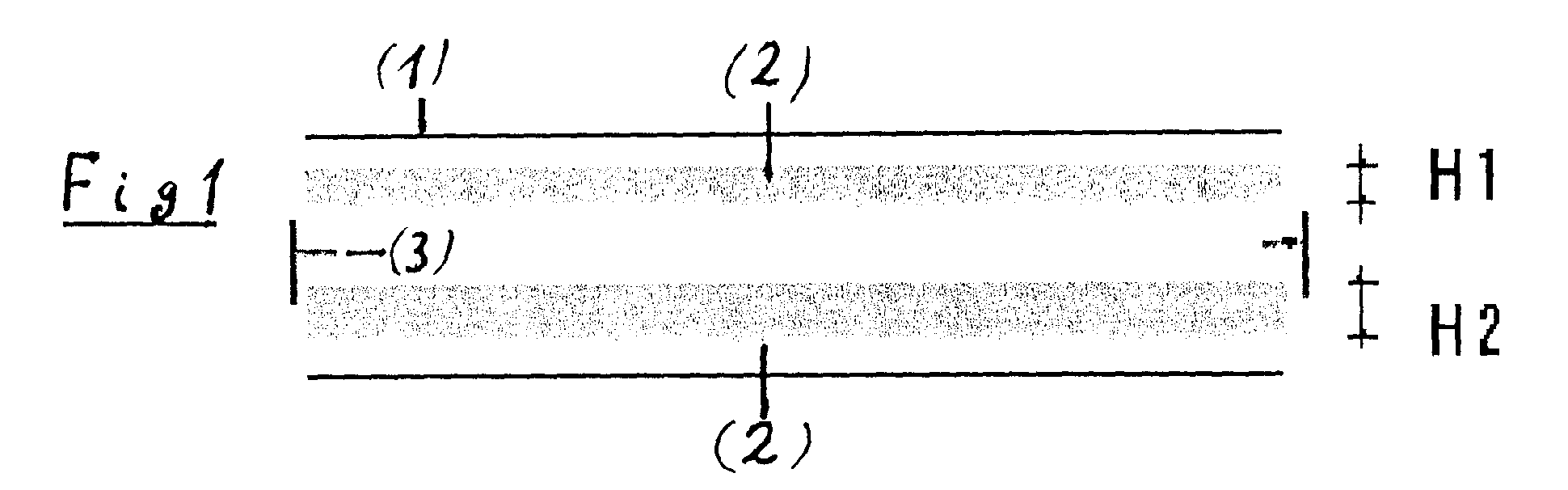
- FIG. 1 The assembly of a sandwich element according to the invention for the application as a door is schematically shown in Fig. 1 .
- the numbers (1) refer to the facing layers, (2) to the core layers and (3) to the contact points which, in this case, are T-shaped.
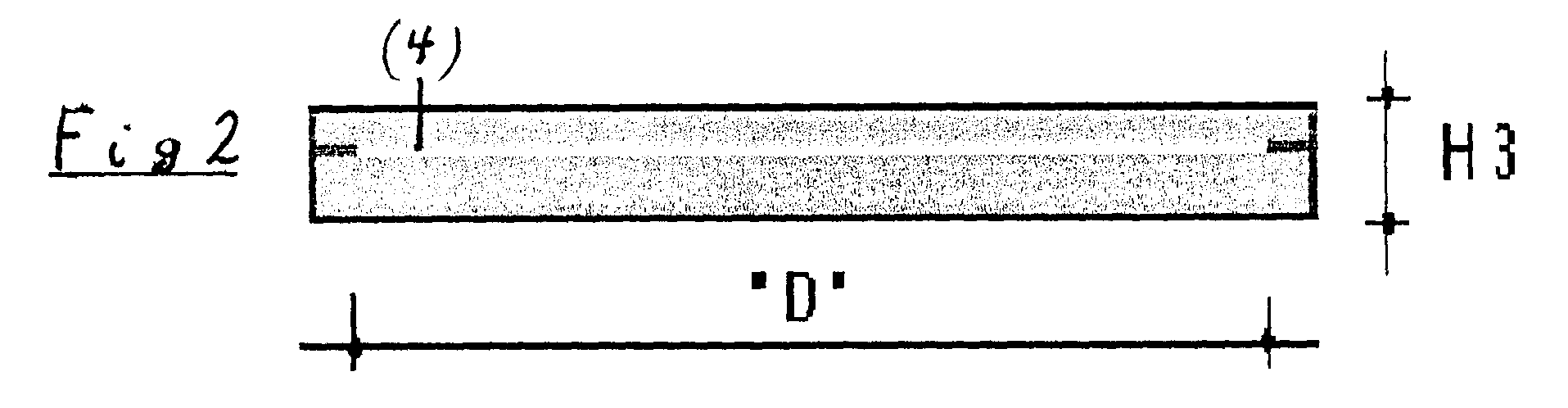
- Figures 2 and 3 show two sandwich elements after having been assembled, the difference of the element according to Fig. 3 as compared to the element according to Fig. 2 being that a third contact point has been incorporated.
- the elements were made from a 20 mm thick polyurethane board and a 40 mm thick polyurethane board (2), which polyurethane had been prepared according to Example 1 of US 5,538,779, and two 1mm thick steel sheets (1) by spray glueing with a contact adhesive (neoprene) at room temperature, one board to one metal sheet and the other board to the second metal sheet, and by joining both assemblies through T-shaped contact points (3), 40 mm wide, and positioned at a distance from each other of 800 mm, as shown in Fig. 2 , and through T-shaped contact points (3) and an additional contact point (3') in the centre, as shown in Fig. 3 , respectively.
- the contact points are 3 mm thick and 40 wide plastic stripes (PE, PU, or PVC, e. g.).
- the two core layers are different in thickness. The reason is that this reduces the negative effect of the characteristic critical frequencies of the facing and the core layers once attached together.
- the air gap (4) is characterized by the thickness generated by the contact points (3) and the distance D .
- the distance D as illustrated in Fig. 2 and Fig. 3 is at least 350 mm, preferably 450 mm or most preferably 600 mm or more as long as mechanical integrity can be preserved
- a door manufactured according to the present invention will achieve excellent dimensional and heat stability with no bowing effect under differential temperature. It will provide thermal insulation and outstanding impact and airborn sound insulation - better than a classic construction of three times more weight.
- a door sandwich element according to the invention was built and tested for its acoustical insulation.
- Fig. 4 illustrates a cross- section and the composition of the tested door of dimension 1050 mm x 2050 mm x 55 mm ( see also Fig. 1 for legend.).
- the facings (1) are 1.5 mm thick steel sheets.
- the core material (2) is a Dow noise insulation foam, as described previously in US 5,538,779.
- the top half has a thickness H 1 of 15 mm and the bottom half H 2 has a thickness of 35 mm.
- Contact points (3) are made of a 30 mm wide foam stripe of 5 mm thickness and 2 050 mm length with a pine timber frame of 15 mm width, 55 mm thickness and running around the four sides of the door panel to provide stiffness and hard edges.
- the test item has a measured weight of 57 kg, i.e only 26 kg / m2.
- the total thickness is 58 mm.
- Fig. 5 illustrates the same door cross section, but for this second test, the contact points stripes (3), both in the center and at the sides, have been glued with contact adhesive to both sides of the core material (2). This attachment method bestows more stiffness on the element.
- Figures 6 and 7 illustrate improved cross -sections of door panels according to the invention, as suitable for industrialization.
- the facings (1) are relatively stiff or stiff ( plywood planks for instance), therefore the need for reinforcing this type is optional and depends on the span D.
- the two halves of the core (the two core layers (2)) have different thicknesses H1 and H2.
- the contact points (3) leave an air gap (4), and a frame (7) runs around the door panel.
- the facings (1) are thin sheets (steel 0. 6 mm thick, for instance). Therefore, it is necessary to stiffen the facings by means of U profiles (6) which are welded or glued to the facings.
- the air gap (4) is very thin and is generated by the thickness of the metal frame (7), which in this specific case replaces the stripes usually used as contact points (3) and forms "bridges" between the core layers.
- stiffening profile or profiles
- Diagonal and cross dispositions are, of course, acceptable as well.
- the assembly of a sandwich element according to the invention for the application as a partition element is schematically shown in Fig. 8 .
- the sandwich element, once assembled, is shown in Fig. 9 .
- the numbers (1) refer to the facing layers, (2) to the core layers and (3) to the contact points which, in this case, belong to the core material itself, since the gap (4), 2 mm thick, is machined out of a single board.
- the gap is not exactly positioned in the center of the panel in order to avoid the accumulated negative effect of similar critical frequencies generated by the two facings when submitted to noise frequencies between approximately 50 Hz and 5000 Hz. In some cases this effect is not detrimental, it all depends on the thickness, modulus and dampening factor of the facings.
- a sandwich element according to the invention to be applied as construction unit is disclosed.
- the core of this element is made of of two bonded planks of a plastic foam material leaving a gap (4) that is centered or preferably off centered.
- the sandwich element has L shaped clay brick facings that encapsulate the core (2) .
- the L shaped facing bricks create a second gap (5) along the vertical edges of the element to provide space for electrical cables etc...
- the gap (5) will be used to pour jointing mortar.
- FIG. 11 Another embodiment of a sandwich element for the application in the construction of walls is demonstrated in Fig. 11 .
- the facings (1) are made of hollow bricks.
- the cavities within the bricks e. g. slots or round holes, are open towards the core of the element.
- the rate of perforation is approximately between 10 % and 80 %, preferably above 30 %. This disposition is characteristic of the invention and will allow to reduce the resonace frequency of the mass spring mass system, while providing some sound absorption benefits at the same time.
Landscapes
- Physics & Mathematics (AREA)
- Acoustics & Sound (AREA)
- Engineering & Computer Science (AREA)
- Architecture (AREA)
- Electromagnetism (AREA)
- Structural Engineering (AREA)
- Civil Engineering (AREA)
- Building Environments (AREA)
- Laminated Bodies (AREA)
- Vehicle Interior And Exterior Ornaments, Soundproofing, And Insulation (AREA)
- Securing Of Glass Panes Or The Like (AREA)
- Soundproofing, Sound Blocking, And Sound Damping (AREA)
- Battery Mounting, Suspending (AREA)
Abstract
Description
- The present invention refers to sound insulating sandwich elements, more specifically to sound insulating multilayered building or construction elements or components such as doors, partitions, walls or ceilings comprising an open-cell, semi-rigid foam core consisting of at least one core material, and comprising one or more than one hollow space or air gap located within the core, and comprising two outer facing layers. More specifically the invention refers to sound insulating sandwich elements, such as doors, partition elements, walls, ceilings, floors, bulkheads, fire doors, traps, lids, flaps, windows, compartment elements, or panels in new or existing buildings. The new sandwich elements are useful in buildings, in the construction industry, or other industries in order to improve the sound insulation performance. Besides, the invention refers to sound insulating elements excelling prior art elements in constructional simplicity, mechanical strength, and rigidity and to the use of such new, sound insulating, multilayered sandwich elements in the construction or other industries for acoustically improving walls, partitions, ceilings, and other parts of the building, structure or machinery.
- In the construction industry it is well known to use panels as partition walls in order to subdivide the building area into seperate areas such as rooms and offices. Usually they consist of an insulating mineral fiber core and two outer facing layers encompassing the core and an air gap or hollow space. The insulating materials such as mineral fibers are arranged between the facing layers in such a manner so as to provide thermal and/or acoustic insulation.
- It is also known to use multilayered sound insulating sandwich elements, laminates or boards, containing mineral fibers as insulation material, as partition elements or compartment elements or panels to be fixed to walls or ceilings to the intention that sound and noise propagation and transmission and sound radiation are reduced. By applying sound insulating elements to walls or ceilings or by using them as partition elements it is possible to upgrade residential buildings or office buildings improving their sound insulation performance. Thus, older constructions can be adjusted to comply with modem often higher regulation standards. Noises from neighbours or external sources or emanating from inside the room can be reduced substantially.
- However, a major disadvantage of such partitions or panels having mineral fiber cores is the lack of mechanical strength of such fibers. For that reason the facing layers must be secured, e. g. by means of screws or frames, and supported by metal or timber studs. This requires an extensive manufacturing process.
- In JA 0221 642 a noise insulating panel is disclosed in which a porous material, such as glass wool or foamed synthetic resin is stacked between facing layers formed by plywood, gypsum board, or an acryl plate in such a manner as to be out of contact with at least one surface material. According to the teaching of this specification, a frame must be used in order to stabilize or fix this condition. This frame is fitted to the above assembly to form a panel. This, of course, is a relatively intricate and hence expensive procedure. Furthermore, it is a well known method extrapolated from conventional timber frame walls or panels.
- DE 3710 057 discloses a multilayered acoustic insulation panel for internal walls which has air gaps between a layer of mineral wool and an outer chipboard facing layer. This insulation panel contains a main panel made of chipboard which is spaced apart by ribs from a facing layer or cover panel which is also made of chipboard. The inner surfaces of these two panels are covered with fiber board which is held in place by glue. For attaining good sound dampening performance the two fiber boards are different in weight. This multilayered panel consists of five layers, i. e. two chipboard layers, each of which is glued to a fiber board, plus a mineral wool layer in the middle of the sandwich serving as acoustic insulation material. The mineral wool fills the space only partly in such a way that an air gap is provided for between the mineral wool and one of the fiber boards which is glued to the inner surface of the cover panel. The latter is secured by screws to the ribs. As can be seen from the description, the design of this multilayered panel is quite complicated. Its fabrication is therefore relatively expensive. The acoustic performance is achieved by increasing the mass rendering such panels difficult to transport and to install.
- According to several proposals, organic plastics have been used instead of mineral fibers, such as, for example, the well-known open-cell polyurethane foam laminates. However, such laminates exhibit the disadvantage of being brittle and having a poor tensile strength (about 30 kPa).
- In U.S. Patent No. 4,317,503 a sound insulating building element is disclosed which includes a plurality of parallel layer elements of which a first inner, thick element is constituted by a layer of mineral fibers or stiff plastic foam and contains a plurality of cavities. A second inner stiff element which is substantially pervious to air is connected to one main surface of the first inner element and an outer impervious element. The outer impervious element is arranged at a small distance from the second inner element in such a manner that substantially the entire outer element can oscillate freely in relation to the second inner element. A major disadvantage of this type of building elements is the complex and costly manufacturing process of such multilayered structures.
- Other known types of partitions are the multilayered structures including those having a foam or honeycomb core. The foam cores, however, although possessing suitable mechanical strength properties, are very poor as far as the sound insulating properties are concerned. In order to overcome this problem, the foam core would have to be of an unacceptable thickness and weight.
- Generally speaking, there are several known types of systems for increasing the sound insulation performance of walls such as:
- Increasing the mass of the wall which is, of course, the most basic way of providing better sound insulation (mass law);
- using resilient panels or sandwich structures the components of which, that is facing layer or layers and core layer, vibrate without phase relation so that part of or most of the incident acoustic energy is converted into mechanical energy, which will be dissipated through internal friction and deformations (mass-spring-mass system).
-
- The drawback of the increase of the mass of the wall or any similar structure following the mass law is that rather heavy and thick structures are required for good performance.
- The drawback of common mass-spring-mass systems is that their resonant frequency will very often disturb the overall performance when it is wrongly positioned and too sharp.
- Better results are obtained by using sound insulating elements or panels as disclosed in WO 95/14 136. Those multilayered insulating panels or elements comprise in a preferred embodiment (a) two outer facing layers, and (b) a soft synthetic core material which is a single, continuous, soft, synthetic foam core layer having cavities and being arranged in intimate contact with both outer layers through contact points in alternate patterns, thereby providing gaps between the core layer and the opposing outer layer.
- What is actually disclosed in the specification, the drawings, the claims and the abstract of WO 95/14 136 is the following:
- a sandwich element comprising two facing layers, e. g. gypsum boards, and a core material between the facing layers;
- the core layer comprises an elastic, closed-cell polyethylene foam, or rigid, closed-cell polyurethane foam, or other closed-cell plastic foams, e. g. based on polyvinyl chloride, or polystyrene;
- the second facing layer can be a brick structure, thus referring indirectly to a wall, to which the core layer can be glued, e.g. with mortar;
- the core layer contains cavities in special geometrical arrangement; there are gaps between the core layer and the facing layers;
- the gaps are confined between the core layer and the facing layers by contact points or areas which are arranged in an alternate pattern with respect to the opposing facings;
- empirical measures and theoretical considerations are applied for best results in the mass-spring-mass-system.
-
- Panels as disclosed in WO 95/14 136 possess both acoustic insulating properties and mechanical strength. While this art provides lighter and cheaper panels with good acoustic properties compared to previously known products, it was still highly desirable to provide room partition elements and sandwich elements such as doors, and partitions having both sound insulating properties and good mechanical strength, which would be particularly useful for up-grading residential and office buildings and for designing partitions with improved sound insulation performance. Also, there was a need for more economical methods for producing and installing such sound insulating panels.
- The previous European Patent Application 98 111 295.6 - 2303 (Dow Case 44,161) is directed to a multilayered, sound insulating panel comprising a facing layer, a plastic foam core layer attached thereto wherein the core layer material is a semi-rigid, cellular material having certain characteristics, a structure, to which the core layer is fixed at seperated contact points by means of stripes, patches, dabs, or other geometrical protrusions (generally called "contact points") leaving gaps between the core layer and the structure, and, in case of long spans and/or thin facing layers, travel stops to keep the core layer at a certain distance from the structure.
- The panels according to EU 98 111 295.6 - 2303 are useful in the construction and other industries for improving the sound insulating properties of buildings and/or machinery.
- Although these sandwich elements are in general suitable as partition elements their mechanical strength may not be sufficient due to the presence of the large gap between the facing and the core in application fields where strength and resistance are of particular importance to the applicability of a construction element, such as in the construction of doors or walls.
- That need and other needs are met by the present invention. Thus the present invention provides a multilayered, sound insulating sandwich element comprising facing layers and a plastic foam core located between the facing layers and attached to the facing layers, the core presenting one ore more than one cavities, which sound insulating element is characterized in that
- the cavity/cavities is/are a gap/gaps which is/are positioned essentially parallel to the facings and is/are located within the core,
- the core material is a semi-rigid, cellular material containing more than 50 %, preferably more than 90 % open cells,
- and has a tensile strength of more than 50 kPa, preferably more than 90 kPa,
- and has a compressive strength from 5 to 200 kPa, preferably from 15 to 80 kPa, at 10 % deformation.
- In a preferred embodiment of the invention there is provided a sandwich element wherein the gap or gaps are defined by two core layers and contact points, also called "bridges", providing structural junctions between the core layers while holding the core layers separated and creating a gap or gaps between the core layers.
-
- The distance between the contact points is preferably at least 350 mm, more preferred is a minimum of 450 mm, or even 600 mm as long as mechanical integrity can be preserved.
- The facing layers may have a thickness, each, from 0.5 to 100 mm, preferably from 0.5 to 25 mm. The facing layer material can be a 0.5 to 20 mm thick metal sheet, preferably steel or aluminium, or a 4 to 25 mm thick wood sheet. Other materials, useful in a specific application field, can be selected by the expert in the art.
- The foam core layer may have a thickness from 20 to 500 mm, preferably from 20 to 300 mm and even more preferred up to 200 mm. Each foam core layer has in general a minimal thickness of 10 mm to achieve significant dampening, preferably a thickness from 15 to 100 mm. It should be noted, however, that these ranges should not be construed as being restrictive. Values outside these ranges may be suited for particular applications, e. g. establishments requiring a very high sound dampening performance.
- The foam core layers may have or not the same thickness. In some cases of facing materials it has been found beneficial to use different thicknesses so as to minimize the negative effect of the characteristic critical frequencies of the assembly made from the facing and the core layers.
- Preferably, the core layer material is a polyurethane foam, for instance of the type whose preparation is disclosed in US Patent No. 5,538,779.
- The core layer material can comprise more than one foam type. For instance, it may include in addition to polyurethane, polyethylene or polystyrene. It may also comprise bitumen or heavy plastic or sheets made of other materials.
- In a preferred embodiment the core layer material has an air flow resistivity from 5 000 to 800 000 Ns/m4, preferably from 5 000 to 300 000 Ns/m4.
- The loss factor of the core layer material is preferably greater than 0.1, preferably greater than 0.2 (as defined by SAE Sound and Heat Insulation Materials Committee, SAE Handbook, 1994,
Volume 1, page 2.30); the loss factor can reach 0.3, or even more. - In the case of long gaps and/or thin facing layers, travel stops are provided at at least one of the core layers and within the gap in order to make sure that the core layers are always kept at a certain distance from each other.
- The distance of the travel stops from the opposite core layer or the distance of the core layers from each other, at 0 % deformation, is preferably at least 0.1 mm, and preferred ranges are between 2 and 10 mm.
- In a preferred embodiment the total contact points area is related to the total area of the sandwich element in a ratio of less than 30 %, preferably less than 15 %.
- In a preferred embodiment the contact points are plastic foam, plastic, metal or wood stripes of a thickness of from 0.5 to 100 mm and a width from 10 to 100 mm. These ranges should, however, not be construed as being restrictive and may vary depending upon the specific stress requirement of the application and the stiffness of the facings. Very rigid facings would for instance allow an air gap of unspecified thickness. Protruding parts of the core layers or even other constructional elements, such as door frames, may assume the function of the contact points or "bridges".
- Furthermore, the present invention provides a process for the fabrication of the new sound insulating sandwich element by attaching the facing layers to the plastic foam core which process is characterized in that the plastic foam core is produced by joining two core layers through contact points or bridges at predetermined distances thus leaving a gap or gaps between the core layers or by first machining two core layers in such a way that contact points or bridges are formed at predetermined distances as integral parts of the core layers and by joining the two core layers afterwards through the contact points or bridges leaving a gap or gaps between the core layers or by cutting out the gap or gaps from a single plastic foam board.
- Furthermore, the present invention provides the use of the new sound insulating sandwich element in the construction and other industries for improving the sound insulating properties of buildings and/or machinery.
- A particularly surprising feature of the invention is that long span vibration of the core layer attached to the facing layer provides particularly good dampening at all frequencies and specifically at the resonant and the critical frequencies.
- The gaps created within the foam core can vary considerably depending on the actual needs in a given case. Very rigid facings would allow an air gap of unspecified thickness. The thickness usually ranges from 0.1 to 200 mm. Sometimes the thickness is selected between 20 and 50 mm so as to allow for passing cables, pipes and other service lines. Apart from those special consideration, the thickness of the gaps is often in the range from 1 to 10 mm, preferably from 2 to 5 mm.
- In case of a plasterboard (or a board from any other material insufficiently stiff) being used as facing layer, and if, for example, the plasterboard is 10 mm thick and its span exceeds 400 mm or is 13 mm thick and its span exceeds 600 mm, respectively, a "mid span" travel stop system made of a stripe or patches can be installed to limit the plasterboard deformation. By way of example, if a 1200 mm wide plasterboard laminate is installed with contact points (stripes) of 40 mm width at the edges of the board, thereby providing for a free span of 1 120 mm, a travel stop stripe will be fixed in the middle of the board in order to reduce the span. The width of the travel stop stripe will be between 30 and 39.9 mm, preferably between 35 and 38 mm, if the contact stripe width is e. g. 40 mm.
- The realization of the invention by adhering to the parameters as defined in the specification and the claims, particularly by using a specific foam material and applying specific designs with regard to the core layer, the facing layer (-s) and the travel stops, will result in a sound insulating sandwich element showing very low resonant frequency and surprisingly high dampening of vibrations, specifically at the resonant frequency, and having high mechanical strength and rigidity, which means that the new elements can be transported and handled without any particular risk of damage. Therefore, additional reinforcement to ensure mechanical integrity of the assembly, such as by means of screws, frames, or studs, is not necessary.
- Nevertheless, other connecting or rigidifying devices can be incorporated, once the components are in place or before the installation, within the element or at the junctions to ensure that the specific requirements of the application are fulfilled. Design arrangements are proposed to prevent any sound bridging to take place while still fulfilling all strength requirements in use. This is within the capacity of the expert in the art.
- Typical reinforcements will be wood or metal frames for the door application, steel studs or beams between panels for the partition application, and mortar or glue for wall application.
- The facing layers can be made of any material typically employed to produce insulating sandwich elements or panels. Exemplary materials useful as facing layers include plastic or particle boards, thick paper or cardboards, fiber boards, gypsum plaster boards, flexible plastic films or foils, metal sheets, such as steel, lead, or aluminium sheets, plywood, timber boards, and chipboards, most typical being gypsum plaster boards, and chipboards. The preferred material for use as facing layer is gypsum board in the partition applications and metal sheet or wood boards in the door applications.
- In one embodiment of the invention, a core layer made of polyurethane foam and having seperated polyurethane foam patches as contact points at one of its two surfaces, is substantially attached by means of adhesives at its "inner" surface to another polyurethane foam core layer, thus forming a core. Usually, such a panel will be prefabricated thereby avoiding assembling on site. The core will then be fixed to the two facing layers, usually by glueing with a suitable adhesive such as polyurethane glue, neoprene contact or transfer adhesive, or by mechanical fixing in order to produce a sandwich element according to the invention.
- The sandwich element thus obtained can be used for instance as doors. The facing material for doors usually are thin layers of metal sheet or wood sheets and are substantially attached to the core layers in order to fulfill requirements such as heat stability, impact deformation resistance, perfectly plane surface and aesthetics. It is therefore important that no gaps are created between the reinforcing foam core and the facing layers when the latter lack stiffness.
- Furthermore, the substantial attachment between facing and core layers, by means of adhesive e. g., provides benefits in so far as the highly dampening core material which is used according to the invention strongly reduces impact and vibration transmission.
- The new sandwich element can also be used for instance as a room partition standing on its own. Such a partition element is usually secured on the floor and/or at the ceiling. It can be fixed to a wall, ceiling, floor, or other building structure.
- The sandwich partition concept as per the invention concerns space dividing units, mostly for offices, industry cabins and other panel applications where the combination of lightweight, easy connecting devices, handability and sound insulation performance are important requirements. These partitions may rest in vertical or horizontal positions but, in some embodiments, they may as well be positioned at acute or obtuse angles.
- It was surprising to find that outstanding sound insulation performance could be achieved by incorporating specific contact points or bridges within the core to create an air gap or air gaps which is therefore a conspicuous feature of the present invention.
- The contact points can be machined from the polyurethane foam layer or can be made from other suitable materials, such as plastics other than polyurethane, glue or other adhesives; wood, plaster, metal etc., as long as the inventive criteria are fulfilled.
- In addition to the door and the partition walls applications of the sandwich element according to the invention, we may highlight a third application field that is the construction unit application. Here the new sandwich elements function like brickstones in a building wall, a ceiling, a floor or any other construction part or unit.
- The new sound insulating sandwich elements are particularly useful for refurbishing existing buildings, but also as elements in new constructions. They can be manufactured as doors or partition elements or wall construction units. They offer a thin, light weight and mechanically strong solution to improve sound insulation, thus eliminating or damping sounds and noises which without the sound insulating elements are transmitted through walls, doors, floors, ceilings and partitions.
- On the basis of examples it will be demonstrated hereunder that the sandwich elements according to the invention are to a surprising degree substantially superior as compared to prior art sound insulating elements with respect to a combination of sound insulation/ mechanical strength/ light weight/thickness properties and production/ installation methods. They excel in mechanical strength as compared to sound insulating sandwich elements of the state of the art, possess a high acoustic dampening performance, reduce and lower the resonant frequency. The gap within the core is acting as a first very soft spring, and the core layers are acting as second hard springs. Because of the hardness of the core layers, the deformation of the element is strongly restricted which makes it compatible with the intended use in buildings.
- The following examples are given to illustrate the invention and should not be interpreted as limiting it in any way.
- The assembly of a sandwich element according to the invention for the application as a door is schematically shown in Fig. 1. The numbers (1) refer to the facing layers, (2) to the core layers and (3) to the contact points which, in this case, are T-shaped. Figures 2 and 3 show two sandwich elements after having been assembled, the difference of the element according to Fig. 3 as compared to the element according to Fig. 2 being that a third contact point has been incorporated.
- The elements were made from a 20 mm thick polyurethane board and a 40 mm thick polyurethane board (2), which polyurethane had been prepared according to Example 1 of US 5,538,779, and two 1mm thick steel sheets (1) by spray glueing with a contact adhesive (neoprene) at room temperature, one board to one metal sheet and the other board to the second metal sheet, and by joining both assemblies through T-shaped contact points (3), 40 mm wide, and positioned at a distance from each other of 800 mm, as shown in Fig. 2, and through T-shaped contact points (3) and an additional contact point (3') in the centre, as shown in Fig. 3, respectively. The contact points are 3 mm thick and 40 wide plastic stripes (PE, PU, or PVC, e. g.).
- It will be noted that the two core layers are different in thickness. The reason is that this reduces the negative effect of the characteristic critical frequencies of the facing and the core layers once attached together.
- Travel stops might be incorporated as required.
- The air gap (4) is characterized by the thickness generated by the contact points (3) and the distance D . The distance D as illustrated in Fig. 2 and Fig. 3 is at least 350 mm, preferably 450 mm or most preferably 600 mm or more as long as mechanical integrity can be preserved
- A door manufactured according to the present invention will achieve excellent dimensional and heat stability with no bowing effect under differential temperature. It will provide thermal insulation and outstanding impact and airborn sound insulation - better than a classic construction of three times more weight.
- With adequate choice of core material thickness and stiffness, excellent planeness and aesthetics will be achieved even with very thin facing materials.
- A door sandwich element according to the invention was built and tested for its acoustical insulation.
- Fig. 4 illustrates a cross- section and the composition of the tested door of
dimension 1050 mm x 2050 mm x 55 mm ( see also Fig. 1 for legend.). The facings (1) are 1.5 mm thick steel sheets. - The core material (2) is a Dow noise insulation foam, as described previously in US 5,538,779. The top half has a
thickness H 1 of 15 mm and thebottom half H 2 has a thickness of 35 mm. - Contact points (3) are made of a 30 mm wide foam stripe of 5 mm thickness and 2 050 mm length with a pine timber frame of 15 mm width, 55 mm thickness and running around the four sides of the door panel to provide stiffness and hard edges.
- As can be seen from the configuration of Fig. 4, that the timber frame is entirely glued with contact Neoprene adhesive to both the foam core and the steel facings, while the foam stripes are only laid there to ensure contact between the two halfes of core material (2) and are not glued.
- The test item has a measured weight of 57 kg, i.e only 26 kg / m2. The total thickness is 58 mm.
- Despite its very low weight and reduced thickness, the door element or panel as per the invention, whose cross section is illustrated in Fig. 4 achieves an amazingly high sound insulation performance of Rw = 49 dB , R pink = 47 dB (A) and R road noise = 41 dB (A).
- None of the available door panels of such weight and thickness comes up with such a level of performance.
- This compares for instance to a solid concrete wall of 90 mm thickness, weight 207 kg / m2, that achieves a sound insulation of R = 47 dB.
- Fig. 5 illustrates the same door cross section, but for this second test, the contact points stripes (3), both in the center and at the sides, have been glued with contact adhesive to both sides of the core material (2). This attachment method bestows more stiffness on the element.
- As expected, the distance D being reduced from 1020 mm ( test 1 ) to 465 mm (test 2) between contact points somewhat affects the sound insulation performance, which remains very high and is still within the scope of the invention.
Rw = 45 dB; R pink = 44 dB (A), R road noise = 37 dB (A). - The two halves of the core (the two core layers (2)) have different thicknesses H1 and H2. The contact points (3) leave an air gap (4), and a frame (7) runs around the door panel.
- Since these U shaped profiles (6) are embedded into the foam core, their own vibration pattern is reduced by the strong dampening capacity of the foam core. It must be understood that other shapes like T profiles or any other profiles (from aluminium, steel, plastic, timber etc...), providing an adequate stiffening effect due to their moment of inertia and specific modulus, are acceptable, too.
- The air gap (4) is very thin and is generated by the thickness of the metal frame (7), which in this specific case replaces the stripes usually used as contact points (3) and forms "bridges" between the core layers. The two layers or halves of the core material (2) have the same thickness (H1 = H2).
- Sometimes, it is more convenient to run the stiffening profile ( or profiles) parallel to the width of the sandwich element and not to the height. Diagonal and cross dispositions are, of course, acceptable as well.
- The assembly of a sandwich element according to the invention for the application as a partition element is schematically shown in Fig. 8. The sandwich element, once assembled, is shown in Fig. 9. The numbers (1) refer to the facing layers, (2) to the core layers and (3) to the contact points which, in this case, belong to the core material itself, since the gap (4), 2 mm thick, is machined out of a single board.
- These new sandwich elements were made from a 25 mm thick polyurethane (according to US 5,538,779) board (2) and two 15 mm thick wood boards (1) by glueing with a contact adhesive on neoprene basis. The contact points, forming part of the core body, are 15 mm wide.
- Preferably, the gap is not exactly positioned in the center of the panel in order to avoid the accumulated negative effect of similar critical frequencies generated by the two facings when submitted to noise frequencies between approximately 50 Hz and 5000 Hz.. In some cases this effect is not detrimental, it all depends on the thickness, modulus and dampening factor of the facings.
- In this example a sandwich element according to the invention to be applied as construction unit is disclosed. With reference to Fig. 10, it is noted that the core of this element is made of of two bonded planks of a plastic foam material leaving a gap (4) that is centered or preferably off centered. The sandwich element has L shaped clay brick facings that encapsulate the core (2) . The L shaped facing bricks create a second gap (5) along the vertical edges of the element to provide space for electrical cables etc... In another embodiment the gap (5) will be used to pour jointing mortar.
- Another embodiment of a sandwich element for the application in the construction of walls is demonstrated in Fig. 11. The facings (1) are made of hollow bricks. The cavities within the bricks, e. g. slots or round holes, are open towards the core of the element. The rate of perforation is approximately between 10 % and 80 %, preferably above 30 %. This disposition is characteristic of the invention and will allow to reduce the resonace frequency of the mass spring mass system, while providing some sound absorption benefits at the same time.
Claims (18)
- A multilayered, sound insulating sandwich element comprising facing layers and a plastic foam core located between the facing layers and attached to the facing layers, the core presenting one ore more than one cavities, characterized in thatthe cavity/cavities is/are a gap/gaps which is/are positioned essentially parallel to the facings and is/are located within the core,the core material is a semi-rigid, cellular material containing more than 50 %, preferably more than 90 % open cells,and has a tensile strength of more than 50 kPa, preferably more than 90 kPa,and has a compressive strength from 5 to 200 kPa, preferably from 15 to 80 kPa, at 10 % deformation.
- Element according to claim 1, characterized in that the gap/gaps is/are defined by two core layers and contact points ("bridges") providing structural junctions between the core layers while keeping them seperated.
- Element according to claim lor 2, characterized in that the distance between the contact points is at least 350 mm, and more preferred is at least 450 ore even at least 600 mm.
- Element according to any one of claims 1 to 3, characterized in that the core layer material is a polyurethane foam.
- Element according to any one of claims 1 to 4, characterized in that the core layer comprises more than one foam type.
- Element according any one of the claims 1 to 5, characterized in that the facing layers have a thickness, each, of from 0.5 to 200 mm, and the foam core layer has a thickness from 5 to 500 mm, preferably from 20 to 200 mm .
- Element according to any one of the claims 1 to 6, characterized in that the foam core layers are different in thickness.
- Element according to any one of the claims 1 to 7, characterized in that the core layer material has an air flow resistivity from 5 000 to 800 000 Ns/m4, preferably from 5 000 to 300 000 Ns/m4.
- Element according to any one of the claims 1 to 8, characterized in that the core layer material has a loss factor of more than 0.1, preferably more than 0.2.
- Element according to any one of the claims 1 to 9, characterized in that travel stops are provided in the case of long gaps and/or thin facing layers at at least one of the core layers and within the gap in order to keep the core layers at a certain distance from each other
- Element according to claim 10, characterized in that the distance of the travel stops from the opposite core layer or the distance of the core layers from each other, at 0 % deformation, is at least 0.1 mm, and preferably ranges from 2 to 10 mm.
- Element according to any one of the claims 1 to 11, characterized in that the total contact points area is related to the total area of the sandwich element in a ratio of less than 30 %, preferably less than 15 %.
- Element according to any one of the claims 1 or 12, characterized in that the facing layer material is metal sheet, preferably steel or aluminium, or wood sheet.
- Element according to any one of the claims 2 or 13, characterized in that the contact points are plastic foam, plastic, metal or wood stripes of a thickness of from 0.5 to 100 mm and a width from 10 to 100 mm.
- Process for the fabrication of the sandwich element according to any one of the claims 1 to 14 by attaching the facing layers to the plastic foam core characterized in that the plastic foam core is produced by joining two core layers through contact points or bridges at predetermined distances thus leaving a gap/gaps between the core layers or by first machining two core layers in such a way that contact points or bridges are formed at predetermined distances as integral parts of the core layers and by joining the two core layers afterwards through the contact points or bridges leaving a gap/gaps between the core layers or by cutting out the gap or gaps from a single foam plastic board.
- Use of the element according to any one of the claims 1 to 14 in the construction and other industries for improving the sound insulating properties of buildings and/or machinery.
- Use according to claim 16, characterized in that the element is used as a door, as a partition element or as a construction unit.
- Use according to claim 17, characterized in that the element is used as a clay brick or gypsum plaster stone.
Priority Applications (17)
| Application Number | Priority Date | Filing Date | Title |
|---|---|---|---|
| EP99111191A EP1061190B1 (en) | 1999-06-09 | 1999-06-09 | Sound insulating sandwich element |
| AT99111191T ATE362024T1 (en) | 1999-06-09 | 1999-06-09 | SANDWICH SOUND ISOLATION ELEMENT |
| DK99111191T DK1061190T3 (en) | 1999-06-09 | 1999-06-09 | Soundproof sandwich element |
| ES99111191T ES2285804T3 (en) | 1999-06-09 | 1999-06-09 | INSTRUMENT INSTRUMENT SOUND INSULATION ELEMENT. |
| PT99111191T PT1061190E (en) | 1999-06-09 | 1999-06-09 | Sound insulating sandwich element |
| DE69936046T DE69936046T2 (en) | 1999-06-09 | 1999-06-09 | Soundproofing sandwich element |
| CA002371354A CA2371354C (en) | 1999-06-09 | 1999-06-18 | Sound-insulating sandwich element |
| US09/979,814 US6789645B1 (en) | 1999-06-09 | 1999-06-18 | Sound-insulating sandwich element |
| AU45774/99A AU771473B2 (en) | 1999-06-09 | 1999-06-18 | Sound-insulating sandwich element |
| KR1020017015815A KR20020022066A (en) | 1999-06-09 | 1999-06-18 | Sound-insulating sandwich element |
| CNB998167118A CN1148501C (en) | 1999-06-09 | 1999-06-18 | Acoustic Sandwich Elements |
| JP2001501706A JP4426141B2 (en) | 1999-06-09 | 1999-06-18 | Sound insulation sandwich element |
| PCT/US1999/013777 WO2000075443A1 (en) | 1999-06-09 | 1999-06-18 | Sound-insulating sandwich element |
| MXPA01012664A MXPA01012664A (en) | 1999-06-09 | 1999-06-18 | Sound-insulating sandwich element. |
| MYPI99002533A MY125896A (en) | 1999-06-09 | 1999-06-18 | Sound-insulating sandwich element |
| BR9917404-9A BR9917404A (en) | 1999-06-09 | 1999-06-18 | Multilayer interleaved element for sound insulation, process for its manufacture and use |
| TW088110342A TW592974B (en) | 1999-06-09 | 1999-06-21 | Multilayered sound-insulating sandwich element and process for making the same |
Applications Claiming Priority (1)
| Application Number | Priority Date | Filing Date | Title |
|---|---|---|---|
| EP99111191A EP1061190B1 (en) | 1999-06-09 | 1999-06-09 | Sound insulating sandwich element |
Publications (2)
| Publication Number | Publication Date |
|---|---|
| EP1061190A1 true EP1061190A1 (en) | 2000-12-20 |
| EP1061190B1 EP1061190B1 (en) | 2007-05-09 |
Family
ID=8238326
Family Applications (1)
| Application Number | Title | Priority Date | Filing Date |
|---|---|---|---|
| EP99111191A Expired - Lifetime EP1061190B1 (en) | 1999-06-09 | 1999-06-09 | Sound insulating sandwich element |
Country Status (16)
| Country | Link |
|---|---|
| EP (1) | EP1061190B1 (en) |
| JP (1) | JP4426141B2 (en) |
| KR (1) | KR20020022066A (en) |
| CN (1) | CN1148501C (en) |
| AT (1) | ATE362024T1 (en) |
| AU (1) | AU771473B2 (en) |
| BR (1) | BR9917404A (en) |
| CA (1) | CA2371354C (en) |
| DE (1) | DE69936046T2 (en) |
| DK (1) | DK1061190T3 (en) |
| ES (1) | ES2285804T3 (en) |
| MX (1) | MXPA01012664A (en) |
| MY (1) | MY125896A (en) |
| PT (1) | PT1061190E (en) |
| TW (1) | TW592974B (en) |
| WO (1) | WO2000075443A1 (en) |
Cited By (11)
| Publication number | Priority date | Publication date | Assignee | Title |
|---|---|---|---|---|
| FR2827323A1 (en) * | 2001-07-16 | 2003-01-17 | Imerys Structure | Insulated hollow construction tile has perforations in insulated surface linked to internal cavities |
| WO2006128632A1 (en) | 2005-05-28 | 2006-12-07 | Airbus Deutschland Gmbh | Sandwich structure having a frequency-selective double-wall behavior |
| GB2434482A (en) * | 2006-01-18 | 2007-07-25 | Gordon James Harris | Angular sound baffle |
| EP2048298A2 (en) | 2007-09-14 | 2009-04-15 | KLH Massivholz GmbH | Floor or ceiling |
| US7631727B2 (en) | 2006-05-24 | 2009-12-15 | Airbus Deutschland Gmbh | Sandwich structure with frequency-selective double wall behavior |
| WO2011020151A1 (en) * | 2009-08-20 | 2011-02-24 | James Hardie Technology Limited | Building system |
| US8973329B2 (en) | 2009-08-20 | 2015-03-10 | James Hardie Technology Limited | Building system with multi-function insulation barrier |
| WO2017134341A1 (en) * | 2016-02-02 | 2017-08-10 | Framery Oy | Wall structure |
| US20170305106A1 (en) * | 2014-09-30 | 2017-10-26 | Sekisui Chemical Co., Ltd. | Heat-conducting foam sheet for electronic devices |
| EP3260289A1 (en) * | 2016-06-09 | 2017-12-27 | Odenwald Chemie GmbH | Compound element |
| ES3056623A1 (en) * | 2024-08-21 | 2026-02-23 | Sna Consultoria Acustica S L | Acoustic insulation panel, acoustic insulation system comprising said panel, and acoustic insulation method |
Families Citing this family (14)
| Publication number | Priority date | Publication date | Assignee | Title |
|---|---|---|---|---|
| AU783624B2 (en) * | 2000-03-17 | 2005-11-17 | Fletcher Challenge Limited | Building Construction |
| JP4684737B2 (en) * | 2005-05-02 | 2011-05-18 | 神鋼鋼線工業株式会社 | Lightweight flooring for vehicles |
| ATE439483T1 (en) * | 2006-03-10 | 2009-08-15 | Basf Se | MULTI-LAYER FOAM COMPOSITE ELEMENT WITH CUTOUTS |
| CN102700181B (en) * | 2012-05-15 | 2014-09-03 | 西安交通大学 | Light multifunctional composite structure |
| SG10201405027SA (en) * | 2014-08-19 | 2016-01-28 | Perfect Sourcing Company Ltd | Composite Panel For Green Building System |
| DE202014104104U1 (en) * | 2014-09-02 | 2014-09-26 | Metawell Gmbh Metal Sandwich Technology | Filled metal sandwich structure |
| CN107620403B (en) * | 2017-09-21 | 2022-11-15 | 南京工业大学 | High Strength Timber Shear Wall with Rubber Connection Structure |
| CN107700686B (en) * | 2017-09-21 | 2023-04-25 | 江苏声立方环保科技有限公司 | Sound absorption and insulation board and manufacturing method thereof |
| CN109138507A (en) * | 2018-07-29 | 2019-01-04 | 广东广凌信息科技股份有限公司 | A kind of sound insulation system of massage voice reading pavilion |
| CN110344510B (en) * | 2019-07-29 | 2020-06-16 | 南京航空航天大学 | A method for making a multi-layer sound insulation wall structure with wave blocking ribs |
| CA3179006A1 (en) * | 2020-06-10 | 2021-12-16 | Westlake Royal Building Products Inc. | Sound control components comprising foam composites |
| US11692350B2 (en) | 2021-06-30 | 2023-07-04 | Solar Turbines Incorporated | Composite noise-attenuating panel system |
| FR3127740B1 (en) | 2021-10-01 | 2023-12-08 | Faiveley Transp Tours | WITH IMPROVED SOUND INSULATION PROPERTIES, |
| CN114083838A (en) * | 2021-12-03 | 2022-02-25 | 青岛理工大学 | Sandwich structure with low-specific-modulus insertion layer and preparation method thereof |
Citations (5)
| Publication number | Priority date | Publication date | Assignee | Title |
|---|---|---|---|---|
| FR2228916A1 (en) * | 1973-05-10 | 1974-12-06 | Hugo Knodler Kg | Soundproof composite building panel - has voids through expanded polystyrene core filled with insulation |
| US4317503A (en) | 1978-11-17 | 1982-03-02 | Ingemanssons Ingenjorsbyra Ab | Sound insulating building element |
| DE3710057A1 (en) | 1987-03-27 | 1988-12-01 | Wenger Wespanwerk Ag | SOUND INSULATING PARTITION |
| DE3940452C1 (en) * | 1989-12-07 | 1991-05-02 | Helmut 5804 Herdecke De Pelzer | Roller shutter for window and door sound insulation - consists of heavy material strips coupled by mat of open-pore foam or felt |
| WO1995014136A1 (en) | 1993-11-19 | 1995-05-26 | The Dow Chemical Company | Acoustic insulating panels or elements |
-
1999
- 1999-06-09 PT PT99111191T patent/PT1061190E/en unknown
- 1999-06-09 DE DE69936046T patent/DE69936046T2/en not_active Expired - Lifetime
- 1999-06-09 AT AT99111191T patent/ATE362024T1/en active
- 1999-06-09 EP EP99111191A patent/EP1061190B1/en not_active Expired - Lifetime
- 1999-06-09 ES ES99111191T patent/ES2285804T3/en not_active Expired - Lifetime
- 1999-06-09 DK DK99111191T patent/DK1061190T3/en active
- 1999-06-18 MY MYPI99002533A patent/MY125896A/en unknown
- 1999-06-18 CA CA002371354A patent/CA2371354C/en not_active Expired - Fee Related
- 1999-06-18 BR BR9917404-9A patent/BR9917404A/en not_active IP Right Cessation
- 1999-06-18 MX MXPA01012664A patent/MXPA01012664A/en not_active IP Right Cessation
- 1999-06-18 CN CNB998167118A patent/CN1148501C/en not_active Expired - Fee Related
- 1999-06-18 WO PCT/US1999/013777 patent/WO2000075443A1/en not_active Ceased
- 1999-06-18 KR KR1020017015815A patent/KR20020022066A/en not_active Withdrawn
- 1999-06-18 AU AU45774/99A patent/AU771473B2/en not_active Ceased
- 1999-06-18 JP JP2001501706A patent/JP4426141B2/en not_active Expired - Fee Related
- 1999-06-21 TW TW088110342A patent/TW592974B/en active
Patent Citations (5)
| Publication number | Priority date | Publication date | Assignee | Title |
|---|---|---|---|---|
| FR2228916A1 (en) * | 1973-05-10 | 1974-12-06 | Hugo Knodler Kg | Soundproof composite building panel - has voids through expanded polystyrene core filled with insulation |
| US4317503A (en) | 1978-11-17 | 1982-03-02 | Ingemanssons Ingenjorsbyra Ab | Sound insulating building element |
| DE3710057A1 (en) | 1987-03-27 | 1988-12-01 | Wenger Wespanwerk Ag | SOUND INSULATING PARTITION |
| DE3940452C1 (en) * | 1989-12-07 | 1991-05-02 | Helmut 5804 Herdecke De Pelzer | Roller shutter for window and door sound insulation - consists of heavy material strips coupled by mat of open-pore foam or felt |
| WO1995014136A1 (en) | 1993-11-19 | 1995-05-26 | The Dow Chemical Company | Acoustic insulating panels or elements |
Cited By (18)
| Publication number | Priority date | Publication date | Assignee | Title |
|---|---|---|---|---|
| FR2827323A1 (en) * | 2001-07-16 | 2003-01-17 | Imerys Structure | Insulated hollow construction tile has perforations in insulated surface linked to internal cavities |
| WO2006128632A1 (en) | 2005-05-28 | 2006-12-07 | Airbus Deutschland Gmbh | Sandwich structure having a frequency-selective double-wall behavior |
| GB2434482A (en) * | 2006-01-18 | 2007-07-25 | Gordon James Harris | Angular sound baffle |
| US7631727B2 (en) | 2006-05-24 | 2009-12-15 | Airbus Deutschland Gmbh | Sandwich structure with frequency-selective double wall behavior |
| EP2048298A2 (en) | 2007-09-14 | 2009-04-15 | KLH Massivholz GmbH | Floor or ceiling |
| WO2011020151A1 (en) * | 2009-08-20 | 2011-02-24 | James Hardie Technology Limited | Building system |
| US8973329B2 (en) | 2009-08-20 | 2015-03-10 | James Hardie Technology Limited | Building system with multi-function insulation barrier |
| AU2010283967B2 (en) * | 2009-08-20 | 2015-05-07 | James Hardie Technology Limited | Building system |
| US10207473B2 (en) * | 2014-09-30 | 2019-02-19 | Sekisui Chemical Co., Ltd. | Heat-conducting foam sheet for electronic devices |
| US20170305106A1 (en) * | 2014-09-30 | 2017-10-26 | Sekisui Chemical Co., Ltd. | Heat-conducting foam sheet for electronic devices |
| EP3411225A1 (en) * | 2016-02-02 | 2018-12-12 | Framery Oy | Wall structure |
| WO2017134341A1 (en) * | 2016-02-02 | 2017-08-10 | Framery Oy | Wall structure |
| US11117350B2 (en) | 2016-02-02 | 2021-09-14 | Framery Oy | Wall structure |
| FI131278B1 (en) * | 2016-02-02 | 2025-01-24 | Framery Oy | Wall structure |
| EP3411225B1 (en) * | 2016-02-02 | 2025-05-28 | Framery Oy | Wall structure |
| EP3260289A1 (en) * | 2016-06-09 | 2017-12-27 | Odenwald Chemie GmbH | Compound element |
| EP3260289B1 (en) | 2016-06-09 | 2020-09-02 | Odenwald-Chemie GmbH | Compound element |
| ES3056623A1 (en) * | 2024-08-21 | 2026-02-23 | Sna Consultoria Acustica S L | Acoustic insulation panel, acoustic insulation system comprising said panel, and acoustic insulation method |
Also Published As
| Publication number | Publication date |
|---|---|
| TW592974B (en) | 2004-06-21 |
| CA2371354A1 (en) | 2000-12-14 |
| WO2000075443A1 (en) | 2000-12-14 |
| BR9917404A (en) | 2002-03-19 |
| ES2285804T3 (en) | 2007-11-16 |
| ATE362024T1 (en) | 2007-06-15 |
| AU4577499A (en) | 2000-12-28 |
| MY125896A (en) | 2006-08-30 |
| MXPA01012664A (en) | 2002-06-04 |
| DE69936046T2 (en) | 2008-01-10 |
| DE69936046D1 (en) | 2007-06-21 |
| CN1148501C (en) | 2004-05-05 |
| KR20020022066A (en) | 2002-03-23 |
| JP2003522305A (en) | 2003-07-22 |
| PT1061190E (en) | 2007-08-16 |
| AU771473B2 (en) | 2004-03-25 |
| EP1061190B1 (en) | 2007-05-09 |
| CA2371354C (en) | 2008-04-22 |
| JP4426141B2 (en) | 2010-03-03 |
| DK1061190T3 (en) | 2007-09-17 |
| CN1352719A (en) | 2002-06-05 |
Similar Documents
| Publication | Publication Date | Title |
|---|---|---|
| US6789645B1 (en) | Sound-insulating sandwich element | |
| EP1061190B1 (en) | Sound insulating sandwich element | |
| JP7246749B2 (en) | Partition wall structure and its construction method | |
| US6711872B2 (en) | Lightweight panel construction | |
| US5661273A (en) | Soundproof wall | |
| EP3814582B1 (en) | Monolithic acoustical system | |
| EP0965701A1 (en) | Sound insulating panel | |
| US20080314680A1 (en) | Sound Transmission Reducing Construction Elements | |
| WO1997047835A1 (en) | Sound insulation system | |
| FI89398B (en) | Foerfarande Foer foerbaettring av ljudisoleringsfoermaogan hos en haolrumsfoersedd byggnadsplatta samt byggnadsplattekombination med god ljudisoleringsfoermaoga | |
| JPH0720248Y2 (en) | Sound insulation structure of buildings | |
| JP5522934B2 (en) | Sound insulation interior structure | |
| EP0885334A1 (en) | Sound deadening panels | |
| CN219033614U (en) | S-shaped double-cavity sound insulation transverse clamping support | |
| WO2000052277A1 (en) | Sound attenuating structural systems and sound attenuating board members used therefor | |
| KR200359829Y1 (en) | Soundproof panel | |
| KR19980087557A (en) | Noise-proof foam aluminum panel with resonance structure | |
| AU2005233209B2 (en) | Construction elements | |
| CN117166672A (en) | High sound insulation integrated prefabricated wall structure and installation method | |
| JPH11350636A (en) | Wall structure for building | |
| KR20050110774A (en) | Soundproof panel | |
| AU2006225188A1 (en) | Sound transmission loss-increasing construction panels | |
| NZ520115A (en) | A panel and related wall structure | |
| HU183573B (en) | Space limiting construction of combined acoustic characteristic |
Legal Events
| Date | Code | Title | Description |
|---|---|---|---|
| PUAI | Public reference made under article 153(3) epc to a published international application that has entered the european phase |
Free format text: ORIGINAL CODE: 0009012 |
|
| AK | Designated contracting states |
Kind code of ref document: A1 Designated state(s): AT BE CH DE DK ES FI FR GB GR IE IT LI NL PT SE |
|
| AX | Request for extension of the european patent |
Free format text: AL;LT;LV;MK;RO;SI |
|
| 17P | Request for examination filed |
Effective date: 20010612 |
|
| AKX | Designation fees paid |
Free format text: AT BE CH DE DK ES FI FR GB GR IE IT LI NL PT SE |
|
| 17Q | First examination report despatched |
Effective date: 20031015 |
|
| GRAP | Despatch of communication of intention to grant a patent |
Free format text: ORIGINAL CODE: EPIDOSNIGR1 |
|
| GRAS | Grant fee paid |
Free format text: ORIGINAL CODE: EPIDOSNIGR3 |
|
| GRAA | (expected) grant |
Free format text: ORIGINAL CODE: 0009210 |
|
| AK | Designated contracting states |
Kind code of ref document: B1 Designated state(s): AT BE CH DE DK ES FI FR GB GR IE IT LI NL PT SE |
|
| REG | Reference to a national code |
Ref country code: GB Ref legal event code: FG4D |
|
| REG | Reference to a national code |
Ref country code: CH Ref legal event code: EP |
|
| REG | Reference to a national code |
Ref country code: IE Ref legal event code: FG4D |
|
| REF | Corresponds to: |
Ref document number: 69936046 Country of ref document: DE Date of ref document: 20070621 Kind code of ref document: P |
|
| REG | Reference to a national code |
Ref country code: SE Ref legal event code: TRGR |
|
| REG | Reference to a national code |
Ref country code: PT Ref legal event code: SC4A Free format text: AVAILABILITY OF NATIONAL TRANSLATION Effective date: 20070802 |
|
| ET | Fr: translation filed | ||
| REG | Reference to a national code |
Ref country code: CH Ref legal event code: NV Representative=s name: FIAMMENGHI-FIAMMENGHI |
|
| REG | Reference to a national code |
Ref country code: GR Ref legal event code: EP Ref document number: 20070402224 Country of ref document: GR |
|
| REG | Reference to a national code |
Ref country code: DK Ref legal event code: T3 |
|
| REG | Reference to a national code |
Ref country code: ES Ref legal event code: FG2A Ref document number: 2285804 Country of ref document: ES Kind code of ref document: T3 |
|
| PLBE | No opposition filed within time limit |
Free format text: ORIGINAL CODE: 0009261 |
|
| STAA | Information on the status of an ep patent application or granted ep patent |
Free format text: STATUS: NO OPPOSITION FILED WITHIN TIME LIMIT |
|
| 26N | No opposition filed |
Effective date: 20080212 |
|
| PGFP | Annual fee paid to national office [announced via postgrant information from national office to epo] |
Ref country code: CH Payment date: 20110614 Year of fee payment: 13 Ref country code: GR Payment date: 20110511 Year of fee payment: 13 Ref country code: IE Payment date: 20110610 Year of fee payment: 13 Ref country code: SE Payment date: 20110613 Year of fee payment: 13 Ref country code: PT Payment date: 20110608 Year of fee payment: 13 Ref country code: FR Payment date: 20110621 Year of fee payment: 13 |
|
| PGFP | Annual fee paid to national office [announced via postgrant information from national office to epo] |
Ref country code: NL Payment date: 20110621 Year of fee payment: 13 Ref country code: FI Payment date: 20110610 Year of fee payment: 13 Ref country code: GB Payment date: 20110608 Year of fee payment: 13 Ref country code: AT Payment date: 20110526 Year of fee payment: 13 Ref country code: DK Payment date: 20110610 Year of fee payment: 13 |
|
| PGFP | Annual fee paid to national office [announced via postgrant information from national office to epo] |
Ref country code: BE Payment date: 20110614 Year of fee payment: 13 Ref country code: IT Payment date: 20110620 Year of fee payment: 13 |
|
| PGFP | Annual fee paid to national office [announced via postgrant information from national office to epo] |
Ref country code: ES Payment date: 20110715 Year of fee payment: 13 |
|
| PGFP | Annual fee paid to national office [announced via postgrant information from national office to epo] |
Ref country code: DE Payment date: 20111230 Year of fee payment: 13 |
|
| REG | Reference to a national code |
Ref country code: PT Ref legal event code: MM4A Free format text: LAPSE DUE TO NON-PAYMENT OF FEES Effective date: 20121210 |
|
| BERE | Be: lapsed |
Owner name: DOW DEUTSCHLAND INC. Effective date: 20120630 |
|
| REG | Reference to a national code |
Ref country code: NL Ref legal event code: V1 Effective date: 20130101 |
|
| REG | Reference to a national code |
Ref country code: DK Ref legal event code: EBP |
|
| REG | Reference to a national code |
Ref country code: SE Ref legal event code: EUG |
|
| PG25 | Lapsed in a contracting state [announced via postgrant information from national office to epo] |
Ref country code: FI Free format text: LAPSE BECAUSE OF NON-PAYMENT OF DUE FEES Effective date: 20120609 |
|
| REG | Reference to a national code |
Ref country code: CH Ref legal event code: PL |
|
| REG | Reference to a national code |
Ref country code: CH Ref legal event code: PL Ref country code: AT Ref legal event code: MM01 Ref document number: 362024 Country of ref document: AT Kind code of ref document: T Effective date: 20120609 |
|
| GBPC | Gb: european patent ceased through non-payment of renewal fee |
Effective date: 20120609 |
|
| PG25 | Lapsed in a contracting state [announced via postgrant information from national office to epo] |
Ref country code: PT Free format text: LAPSE BECAUSE OF NON-PAYMENT OF DUE FEES Effective date: 20121210 Ref country code: IT Free format text: LAPSE BECAUSE OF NON-PAYMENT OF DUE FEES Effective date: 20120609 Ref country code: SE Free format text: LAPSE BECAUSE OF NON-PAYMENT OF DUE FEES Effective date: 20120610 |
|
| REG | Reference to a national code |
Ref country code: GR Ref legal event code: ML Ref document number: 20070402224 Country of ref document: GR Effective date: 20130104 |
|
| REG | Reference to a national code |
Ref country code: IE Ref legal event code: MM4A |
|
| REG | Reference to a national code |
Ref country code: FR Ref legal event code: ST Effective date: 20130228 |
|
| PG25 | Lapsed in a contracting state [announced via postgrant information from national office to epo] |
Ref country code: GB Free format text: LAPSE BECAUSE OF NON-PAYMENT OF DUE FEES Effective date: 20120609 Ref country code: NL Free format text: LAPSE BECAUSE OF NON-PAYMENT OF DUE FEES Effective date: 20130101 Ref country code: LI Free format text: LAPSE BECAUSE OF NON-PAYMENT OF DUE FEES Effective date: 20120630 Ref country code: BE Free format text: LAPSE BECAUSE OF NON-PAYMENT OF DUE FEES Effective date: 20120630 Ref country code: FR Free format text: LAPSE BECAUSE OF NON-PAYMENT OF DUE FEES Effective date: 20120702 Ref country code: CH Free format text: LAPSE BECAUSE OF NON-PAYMENT OF DUE FEES Effective date: 20120630 Ref country code: DE Free format text: LAPSE BECAUSE OF NON-PAYMENT OF DUE FEES Effective date: 20130101 Ref country code: IE Free format text: LAPSE BECAUSE OF NON-PAYMENT OF DUE FEES Effective date: 20120609 |
|
| REG | Reference to a national code |
Ref country code: DE Ref legal event code: R119 Ref document number: 69936046 Country of ref document: DE Effective date: 20130101 |
|
| PG25 | Lapsed in a contracting state [announced via postgrant information from national office to epo] |
Ref country code: GR Free format text: LAPSE BECAUSE OF NON-PAYMENT OF DUE FEES Effective date: 20130104 |
|
| PG25 | Lapsed in a contracting state [announced via postgrant information from national office to epo] |
Ref country code: AT Free format text: LAPSE BECAUSE OF NON-PAYMENT OF DUE FEES Effective date: 20120609 |
|
| PG25 | Lapsed in a contracting state [announced via postgrant information from national office to epo] |
Ref country code: DK Free format text: LAPSE BECAUSE OF NON-PAYMENT OF DUE FEES Effective date: 20120702 |
|
| REG | Reference to a national code |
Ref country code: ES Ref legal event code: FD2A Effective date: 20131022 |
|
| PG25 | Lapsed in a contracting state [announced via postgrant information from national office to epo] |
Ref country code: ES Free format text: LAPSE BECAUSE OF NON-PAYMENT OF DUE FEES Effective date: 20120610 |