EP1064833B1 - Sägerät - Google Patents
Sägerät Download PDFInfo
- Publication number
- EP1064833B1 EP1064833B1 EP00112229A EP00112229A EP1064833B1 EP 1064833 B1 EP1064833 B1 EP 1064833B1 EP 00112229 A EP00112229 A EP 00112229A EP 00112229 A EP00112229 A EP 00112229A EP 1064833 B1 EP1064833 B1 EP 1064833B1
- Authority
- EP
- European Patent Office
- Prior art keywords
- product
- metering
- measuring
- pneumatic
- sensor
- Prior art date
- Legal status (The legal status is an assumption and is not a legal conclusion. Google has not performed a legal analysis and makes no representation as to the accuracy of the status listed.)
- Expired - Lifetime
Links
Images

Classifications
-
- A—HUMAN NECESSITIES
- A01—AGRICULTURE; FORESTRY; ANIMAL HUSBANDRY; HUNTING; TRAPPING; FISHING
- A01C—PLANTING; SOWING; FERTILISING
- A01C7/00—Sowing
- A01C7/04—Single-grain seeders with or without suction devices
- A01C7/042—Single-grain seeders with or without suction devices using pneumatic means
- A01C7/044—Pneumatic seed wheels
-
- A—HUMAN NECESSITIES
- A01—AGRICULTURE; FORESTRY; ANIMAL HUSBANDRY; HUNTING; TRAPPING; FISHING
- A01C—PLANTING; SOWING; FERTILISING
- A01C7/00—Sowing
- A01C7/08—Broadcast seeders; Seeders depositing seeds in rows
- A01C7/10—Devices for adjusting the seed-box ; Regulation of machines for depositing quantities at intervals
- A01C7/102—Regulating or controlling the seed rate
- A01C7/105—Seed sensors
-
- A—HUMAN NECESSITIES
- A01—AGRICULTURE; FORESTRY; ANIMAL HUSBANDRY; HUNTING; TRAPPING; FISHING
- A01C—PLANTING; SOWING; FERTILISING
- A01C7/00—Sowing
- A01C7/08—Broadcast seeders; Seeders depositing seeds in rows
- A01C7/12—Seeders with feeding wheels
- A01C7/123—Housings for feed rollers or wheels
- A01C7/125—Housings for feed rollers or wheels with bottom delivery of the seeds
-
- Y—GENERAL TAGGING OF NEW TECHNOLOGICAL DEVELOPMENTS; GENERAL TAGGING OF CROSS-SECTIONAL TECHNOLOGIES SPANNING OVER SEVERAL SECTIONS OF THE IPC; TECHNICAL SUBJECTS COVERED BY FORMER USPC CROSS-REFERENCE ART COLLECTIONS [XRACs] AND DIGESTS
- Y02—TECHNOLOGIES OR APPLICATIONS FOR MITIGATION OR ADAPTATION AGAINST CLIMATE CHANGE
- Y02P—CLIMATE CHANGE MITIGATION TECHNOLOGIES IN THE PRODUCTION OR PROCESSING OF GOODS
- Y02P60/00—Technologies relating to agriculture, livestock or agroalimentary industries
Definitions
- the invention relates to a measuring system for a seeder, with a Measuring chamber, which has an inlet channel for receiving product and having an outlet channel for dispensing metered product, wherein a rotatable measuring element, in particular a measuring cylinder, is arranged in the measuring chamber, and a corresponding Seeder.
- Pneumatic planters are usually pulled by tractors and bring out seed and / or fertilizer on a field.
- a pneumatic sowing machine in combination with a tillage machine behind a field be pulled to seed and fertilizer under the soil surface too bring.
- a pneumatic planter has a main component as one Delivery wagon with wheels, one or more at one Frame mounted product tank (s) for receiving products which are usually seed and / or Fertilizer trades.
- Pneumatic planters generally point each also associated with a product tank measuring systems, to from the respective tank measured products supply the pneumatic distribution system, the metered Feeding products to the ground.
- pneumatic planters are with volumetric Measuring systems provided a fixed volume of seed measure per linear unit of length. These volumetric measuring systems typically have either Screw conveyor or grooved cylinder (measuring rollers) on.
- the measuring systems turn to metered products in one to introduce pneumatic distribution system.
- the pneumatic Distribution system of a pneumatic planter exhibits in Generally, a fan to at least one air flow provided by the pneumatic distribution system up to flows to coulters, where the product is deposited in the ground.
- Measured products are made by means of a pneumatic Primary distributor, which is arranged below the measuring system, introduced into the airflow. The products are by the Air flow through distribution lines to a number of Secondary distributors (so-called headers or headers) spent, in turn, the products through individual lines distribute on coulters, which furrow or bottom openers of Run after the tillage implement.
- the measuring system of a (especially pneumatic) sowing machine is vertically between a product tank and a primary distributor arranged.
- the measuring system has an inlet channel and a Outlet channel on.
- Product from the product tank is in the Intake channel received from where it fed to the measuring chamber becomes.
- a measuring cylinder is arranged in the measuring chamber to the to measure product coming from the product tank.
- the measuring cylinder may be a grooved roller or a screw conveyor. After the product has been measured, it is replaced by a Outlet channel fed to the primary manifold.
- optical sensors for passing product Located upstream of the primary distributor in the outlet duct to the to monitor the proper operation of the measuring system.
- a pneumatic seed drill 10 comprises a Ausbringgutwagen 12 and a harrow 14.
- the Ausbringgutwagen 12 is usually by means of a tractor pulled over a field on which seed is to be spread.
- the Ausbringgutwagen 12 has a frame 16, a first Product tank 18 and a second product tank 19 carries. Wheels 20 are rotatably mounted on the frame 16.
- Both product tanks 18 and 19 are identical measuring systems 22 and primary distributors 26th fitted. Only the measuring tank associated with the product tank 18 22 and the associated primary distributor 26 are shown. Both Measuring systems 22 are below the Product tanks 18, 19 are arranged and made with products thereof to put the products in a controlled manner pneumatic distribution system 24 introduce.
- the pneumatic Primary manifolds 26 are disposed below the measuring systems 22. Both primary manifolds 26 are part of the pneumatic Distribution system 24.
- Figure 1 illustrates a so-called double Shot seeder, in which a first, in the product tank 18th included product in the upper area of the air flow and the product contained in the second tank 19 in the lower Area of the air flow is passed.
- the Soil cultivation device 14 is pulled by Ausbringgutwagen 12 and includes a frame 28 at the bottom or furrow opener 30 are attached.
- the harrow 14 may also with Be equipped to close the furrow, such as For example, closing wheels or compressors 32.
- the pneumatic distribution system 24 carries metered products from the product tanks 18, 19 to the furrow openers 30. In the the products contained in the product tanks 18, 19 can sow, Fertilizer or other granular (granular) products.
- the pneumatic distribution system 24 includes a blower 34, the is driven by a hydraulic motor, and a Stream of pressurized air through an adjustable Air chamber 36 passes.
- the air chamber 36 directs her from her deformed air flow in an upper row of tubes 38 and in a bottom row of tubes 39. Typically, both include Rows of pipes have several pipes to accommodate measured Products.
- the upper row of tubes 38 passes the upper one Area of the air flow in an upper row of Venturi tubes 40th in the primary distributors 26, the product tanks 18, 19 assigned.
- the bottom row of Pipes 39 the lower portion of the air flow in a lower Row of venturi tubes 41 in the primary manifolds 26.
- Each of the tubes 38 of the upper row extends from Primary distributor 26, which is assigned to the product tank 19, after behind up to one secondary distributor 44 each Secondary distributor 44 has individual tubes 46 which extend to to the furrow openers 30 extend.
- each tube of the lower row of tubes 39 extends from Primary distributor 26, which is associated with the tank 19, up to a single secondary distributor 44.
- the secondary distributor 44 are identical and include an upwardly extending one Pipe, which has a head part, which in the air stream contained products through the individual tubes 46 on the single furrow opener 30 distributed.
- Products from the product tanks 18 and 19 are by the each measuring systems 22 measured.
- the products go through Venturi tubes 40 or 41 into the airflow.
- the Primary manifolds 26 are provided with a first selector valve 48 provided between the first measuring system 22 and the Venturi tubes 40 and 41 are arranged to select products either in the top row of Venturi tubes 40 or the leading bottom row of Venturi tubes 41.
- first selector valve 48 provided between the first measuring system 22 and the Venturi tubes 40 and 41 are arranged to select products either in the top row of Venturi tubes 40 or the leading bottom row of Venturi tubes 41.
- Product from the product tank 18 in the upper air flow and Product be routed out of product tank 19, as by the Position of the selector valve 48 is specified.
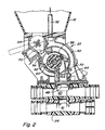
- Pressurized air from the air streams is used to pressurize the product tanks 18, 19. In the concrete Part of the airflow through a channel 50 in the measuring system 22 and into the tube 52 to the product tank 18 under To put pressure.
- Product from product tank 18 bypasses check valve 54 through an inlet channel 56 into a measuring chamber 58, in which is a fluted cylinder 60 which passes through a Hexagonal shaft 62 is driven.
- the measured product is controlled by an exhaust passage 64 depending on the position of Selection valve 48 one of the Venturi tubes 40 or 41 supplied.
- Optical sensors 70 may be in the inlet channel 56 or in the Outlet channel 64 may be arranged to pass the product through these channels.
- the outlet channel 64 is the more desirable position, as one arranged in this channel Sensor the product flow from the measuring system 22 to the pneumatic Distributor system 24 detected.
- the sensors can be of the type No. 5,650,609 A or US 5,847,389 A which are incorporated herein by reference.
Landscapes
- Life Sciences & Earth Sciences (AREA)
- Soil Sciences (AREA)
- Environmental Sciences (AREA)
- Sowing (AREA)
- Fertilizing (AREA)
Description
- Fig. 1
- eine Seitenansicht eines pneumatischen Sägerätes, und
- Fig. 2
- eine Querschnitt durch ein Messsystem und einen Primärverteiler.
Claims (6)
- Messsystem (22) für ein Sägerät (10), mit einer Messkammer (58), die einen Einlasskanal (56) zur Aufnahme von Produkt und einen Auslasskanal (64) zum Abgeben abgemessenen Produkts aufweist, wobei ein drehbares Messelement, insbesondere ein Messzylinder (60), in der Messkammer (58) angeordnet ist, dadurch gekennzeichnet, dass ein Sensor (70) zum Erfassen des Durchgangs von Produkt im Auslasskanal (64) des Messsystems (22) angeordnet ist.
- Messsystem nach Anspruch 1, dadurch gekennzeichnet, dass der Sensor (70) ein optischer Sensor ist.
- Pneumatisches Sägerät (10), mit einem Produkttank (18, 19), aus dem Produkt einem Messsystem (22) mit einer Messkammer (58) zuführbar ist, wobei das Messsystem (22) eingerichtet ist, abgemessenes Produkt einem Primärverteiler (26) zuzuführen, und mit einem Sensor (70) zum Erfassen des Durchgangs von Produkt, dadurch gekennzeichnet, dass der Sensor (70) zum Erfassen des Durchgangs von Produkt im Auslasskanal (64) des Messsystems (22) angeordnet ist.
- Sägerät nach Anspruch 3, dadurch gekennzeichnet, dass der Sensor (70) ein optischer Sensor ist.
- Sägerät nach einem der Ansprüche 3 oder 4, dadurch gekennzeichnet, dass in einer Messkammer (58) ein Messelement, insbesondere ein ausgekehlter Messzylinder (60) zum Abmessen von Produkt angeordnet ist.
- Sägerät nach einem der Ansprüche 3 bis 5, dadurch gekennzeichnet, dass der Produkttank (18, 19) unter Überdruck steht.
Applications Claiming Priority (2)
| Application Number | Priority Date | Filing Date | Title |
|---|---|---|---|
| US09/340,968 US6320183B1 (en) | 1999-06-28 | 1999-06-28 | Product sensors for air seeder |
| US340968 | 1999-06-28 |
Publications (3)
| Publication Number | Publication Date |
|---|---|
| EP1064833A2 EP1064833A2 (de) | 2001-01-03 |
| EP1064833A3 EP1064833A3 (de) | 2002-05-15 |
| EP1064833B1 true EP1064833B1 (de) | 2005-11-02 |
Family
ID=23335700
Family Applications (1)
| Application Number | Title | Priority Date | Filing Date |
|---|---|---|---|
| EP00112229A Expired - Lifetime EP1064833B1 (de) | 1999-06-28 | 2000-06-07 | Sägerät |
Country Status (10)
| Country | Link |
|---|---|
| US (1) | US6320183B1 (de) |
| EP (1) | EP1064833B1 (de) |
| AR (1) | AR025847A1 (de) |
| AU (1) | AU766950B2 (de) |
| BR (1) | BR0002894B1 (de) |
| CA (1) | CA2298989C (de) |
| CZ (1) | CZ298014B6 (de) |
| DE (1) | DE50011489D1 (de) |
| ES (1) | ES2246772T3 (de) |
| HU (1) | HUP0002439A3 (de) |
Cited By (3)
| Publication number | Priority date | Publication date | Assignee | Title |
|---|---|---|---|---|
| EP2489251A1 (de) | 2011-02-19 | 2012-08-22 | Amazonen-Werke H. Dreyer GmbH & Co. KG | Pneumatischer Dosierer |
| EP2489252A1 (de) | 2011-02-19 | 2012-08-22 | Amazonen-Werke H. Dreyer GmbH & Co. KG | Pneumatischer Dosierer |
| DE102011056738A1 (de) | 2011-02-19 | 2012-08-23 | Amazonen-Werke H. Dreyer Gmbh & Co. Kg | Pneumatischer Dosierer |
Families Citing this family (10)
| Publication number | Priority date | Publication date | Assignee | Title |
|---|---|---|---|---|
| AU2003214187A1 (en) * | 2002-03-15 | 2003-09-29 | Finn Corporation | Bulk material discharge assembly with feeding apparatus |
| US7171913B1 (en) * | 2006-02-24 | 2007-02-06 | Amvac Chemical Corporation | Self-calibrating meter with in-meter diffuser |
| US20100264163A1 (en) * | 2008-11-13 | 2010-10-21 | Tevs Nikolai R | Product Dispensing Apparatus And Method |
| CN106134587A (zh) * | 2016-08-24 | 2016-11-23 | 瓦房店明运农机装备有限公司 | 一种气吸式精量播种器 |
| US10905043B2 (en) | 2018-01-22 | 2021-02-02 | Daniel J. Altepeter | Flow control system |
| BR202018077137U2 (pt) * | 2018-12-26 | 2020-07-07 | Stara S/a. Industria De Implementos Agrícolas | disposição introduzida em sistema de distribuição pneumática de produtos sólidos para máquinas e implementos agrícolas |
| CN109819736A (zh) * | 2019-04-03 | 2019-05-31 | 华中农业大学 | 稻麦兼用的气力式精量排种器 |
| CN112042432B (zh) * | 2020-09-16 | 2022-07-12 | 山东安信种苗股份有限公司 | 蔬菜种子精播机 |
| BR102022013360A2 (pt) * | 2022-07-04 | 2024-01-16 | Stara S/a. Industria De Implementos Agrícolas | Interface de distribuição de dosadores |
| CA3233369A1 (en) * | 2023-04-03 | 2025-06-23 | Bourgault Industries Ltd. | Flow control apparatus for agricultural product distribution system |
Family Cites Families (5)
| Publication number | Priority date | Publication date | Assignee | Title |
|---|---|---|---|---|
| US4163507A (en) * | 1978-03-20 | 1979-08-07 | International Tapetronics Corporation | Optical seed sensor for a seed planter monitor |
| US5650609A (en) | 1995-05-15 | 1997-07-22 | Phoenix International Corporation | Seed monitoring system for counting seeds as they are dispensed through a seed planting tube |
| US5601209A (en) * | 1995-07-10 | 1997-02-11 | Morris Industries, Ltd. | Seed metering apparatus |
| US5969340A (en) * | 1995-09-22 | 1999-10-19 | Vansco Electronics Ltd. | Seed counting apparatus for a planter monitor |
| US5855303A (en) | 1997-08-18 | 1999-01-05 | Deere & Company | Wear insert for metering system |
-
1999
- 1999-06-28 US US09/340,968 patent/US6320183B1/en not_active Expired - Lifetime
-
2000
- 2000-02-18 CA CA002298989A patent/CA2298989C/en not_active Expired - Fee Related
- 2000-06-06 CZ CZ20002098A patent/CZ298014B6/cs not_active IP Right Cessation
- 2000-06-07 DE DE50011489T patent/DE50011489D1/de not_active Expired - Lifetime
- 2000-06-07 EP EP00112229A patent/EP1064833B1/de not_active Expired - Lifetime
- 2000-06-07 ES ES00112229T patent/ES2246772T3/es not_active Expired - Lifetime
- 2000-06-20 AU AU42537/00A patent/AU766950B2/en not_active Ceased
- 2000-06-27 HU HU0002439A patent/HUP0002439A3/hu unknown
- 2000-06-27 AR ARP000103217A patent/AR025847A1/es not_active Application Discontinuation
- 2000-06-27 BR BRPI0002894-0A patent/BR0002894B1/pt not_active IP Right Cessation
Cited By (4)
| Publication number | Priority date | Publication date | Assignee | Title |
|---|---|---|---|---|
| EP2489251A1 (de) | 2011-02-19 | 2012-08-22 | Amazonen-Werke H. Dreyer GmbH & Co. KG | Pneumatischer Dosierer |
| EP2489252A1 (de) | 2011-02-19 | 2012-08-22 | Amazonen-Werke H. Dreyer GmbH & Co. KG | Pneumatischer Dosierer |
| DE102011056738A1 (de) | 2011-02-19 | 2012-08-23 | Amazonen-Werke H. Dreyer Gmbh & Co. Kg | Pneumatischer Dosierer |
| DE102011000830A1 (de) | 2011-02-19 | 2012-08-23 | Amazonen-Werke H. Dreyer Gmbh & Co. Kg | Pneumatischer Dosierer |
Also Published As
| Publication number | Publication date |
|---|---|
| ES2246772T3 (es) | 2006-03-01 |
| CZ20002098A3 (cs) | 2001-02-14 |
| AU4253700A (en) | 2001-01-04 |
| US6320183B1 (en) | 2001-11-20 |
| HU0002439D0 (en) | 2000-08-28 |
| AR025847A1 (es) | 2002-12-18 |
| BR0002894B1 (pt) | 2008-11-18 |
| CA2298989C (en) | 2003-11-18 |
| HUP0002439A3 (en) | 2003-02-28 |
| AU766950B2 (en) | 2003-10-30 |
| CZ298014B6 (cs) | 2007-05-23 |
| BR0002894A (pt) | 2001-01-30 |
| DE50011489D1 (de) | 2005-12-08 |
| HUP0002439A2 (hu) | 2001-10-28 |
| EP1064833A3 (de) | 2002-05-15 |
| EP1064833A2 (de) | 2001-01-03 |
| CA2298989A1 (en) | 2000-12-28 |
Similar Documents
| Publication | Publication Date | Title |
|---|---|---|
| EP1164827B1 (de) | Pneumatischer verteiler | |
| EP2932818B1 (de) | Verteilvorrichtung und Verfahren zum Ausbringen von granulatartigem Verteilgut | |
| EP3284332B1 (de) | Verteilmaschine und verfahren zur aussaat von granulatartigem verteilgut | |
| EP1064833B1 (de) | Sägerät | |
| EP1135980B1 (de) | Sämaschine und pneumatisches Reduzierelement | |
| EP3417689B1 (de) | Landwirtschaftliche pneumatische verteilmaschine | |
| EP1329149B1 (de) | Sämaschine | |
| DE102020204701A1 (de) | System zur Verteilung von Saatgut und landwirtschaftlichen Partikeln | |
| EP3788855A1 (de) | Landwirtschaftliche einzelkornsämaschine und verfahren | |
| EP0732044B1 (de) | Rohr für eine landwirtschaftliche Maschine | |
| EP3417688B1 (de) | Landwirtschaftliche pneumatische verteilmaschine | |
| US12484471B2 (en) | Integrated air entrainer segment air source | |
| DE3889531T2 (de) | Landwirtschaftliche Maschine, um ein Produkt zu streuen. | |
| DE102008050735A1 (de) | Pneumatische Direktsämaschine | |
| DE3622078A1 (de) | Pneumatische verteilmaschine | |
| DE19745098C2 (de) | Pneumatische Dillmaschine mit Saatgutrückführung | |
| US20250089602A1 (en) | Agricultural Implement and Method of Operating Agricultural Implement | |
| DE102004025758A1 (de) | Pneumatische Verteilmaschine mit fördergutspezifischer Gebläseeinstellung | |
| EP0800758B1 (de) | Düngevorrichtung | |
| EP2816884A1 (de) | Saemaschine | |
| DE19800486C2 (de) | Pneumatische Drillmaschine oder pneumatischer Düngerstreuer | |
| EP1557078A1 (de) | Elektronische Vorrichtung zum Zählen kleiner Körperchen | |
| EP4305943A1 (de) | Anordnung zur pneumatischen förderung eines hilfsstoffs zu reiheneinheiten einer sämaschine | |
| DE3704126C2 (de) | ||
| DE19535016A1 (de) | Pneumatische Verteilmaschine |
Legal Events
| Date | Code | Title | Description |
|---|---|---|---|
| PUAI | Public reference made under article 153(3) epc to a published international application that has entered the european phase |
Free format text: ORIGINAL CODE: 0009012 |
|
| AK | Designated contracting states |
Kind code of ref document: A2 Designated state(s): AT BE CH CY DE DK ES FI FR GB GR IE IT LI LU MC NL PT SE |
|
| AX | Request for extension of the european patent |
Free format text: AL;LT;LV;MK;RO;SI |
|
| PUAL | Search report despatched |
Free format text: ORIGINAL CODE: 0009013 |
|
| AK | Designated contracting states |
Kind code of ref document: A3 Designated state(s): AT BE CH CY DE DK ES FI FR GB GR IE IT LI LU MC NL PT SE |
|
| AX | Request for extension of the european patent |
Free format text: AL;LT;LV;MK;RO;SI |
|
| 17P | Request for examination filed |
Effective date: 20021115 |
|
| AKX | Designation fees paid |
Designated state(s): DE ES FR GB IT |
|
| 17Q | First examination report despatched |
Effective date: 20040302 |
|
| GRAP | Despatch of communication of intention to grant a patent |
Free format text: ORIGINAL CODE: EPIDOSNIGR1 |
|
| GRAS | Grant fee paid |
Free format text: ORIGINAL CODE: EPIDOSNIGR3 |
|
| GRAA | (expected) grant |
Free format text: ORIGINAL CODE: 0009210 |
|
| AK | Designated contracting states |
Kind code of ref document: B1 Designated state(s): DE ES FR GB IT |
|
| REG | Reference to a national code |
Ref country code: GB Ref legal event code: FG4D Free format text: NOT ENGLISH |
|
| REF | Corresponds to: |
Ref document number: 50011489 Country of ref document: DE Date of ref document: 20051208 Kind code of ref document: P |
|
| GBT | Gb: translation of ep patent filed (gb section 77(6)(a)/1977) | ||
| REG | Reference to a national code |
Ref country code: ES Ref legal event code: FG2A Ref document number: 2246772 Country of ref document: ES Kind code of ref document: T3 |
|
| ET | Fr: translation filed | ||
| PLBE | No opposition filed within time limit |
Free format text: ORIGINAL CODE: 0009261 |
|
| STAA | Information on the status of an ep patent application or granted ep patent |
Free format text: STATUS: NO OPPOSITION FILED WITHIN TIME LIMIT |
|
| 26N | No opposition filed |
Effective date: 20060803 |
|
| PGFP | Annual fee paid to national office [announced via postgrant information from national office to epo] |
Ref country code: GB Payment date: 20140627 Year of fee payment: 15 |
|
| PGFP | Annual fee paid to national office [announced via postgrant information from national office to epo] |
Ref country code: IT Payment date: 20140625 Year of fee payment: 15 Ref country code: ES Payment date: 20140626 Year of fee payment: 15 |
|
| PG25 | Lapsed in a contracting state [announced via postgrant information from national office to epo] |
Ref country code: IT Free format text: LAPSE BECAUSE OF NON-PAYMENT OF DUE FEES Effective date: 20150607 |
|
| GBPC | Gb: european patent ceased through non-payment of renewal fee |
Effective date: 20150607 |
|
| PG25 | Lapsed in a contracting state [announced via postgrant information from national office to epo] |
Ref country code: GB Free format text: LAPSE BECAUSE OF NON-PAYMENT OF DUE FEES Effective date: 20150607 |
|
| REG | Reference to a national code |
Ref country code: FR Ref legal event code: PLFP Year of fee payment: 17 |
|
| REG | Reference to a national code |
Ref country code: ES Ref legal event code: FD2A Effective date: 20160728 |
|
| PG25 | Lapsed in a contracting state [announced via postgrant information from national office to epo] |
Ref country code: ES Free format text: LAPSE BECAUSE OF NON-PAYMENT OF DUE FEES Effective date: 20150608 |
|
| REG | Reference to a national code |
Ref country code: FR Ref legal event code: PLFP Year of fee payment: 18 |
|
| PGFP | Annual fee paid to national office [announced via postgrant information from national office to epo] |
Ref country code: DE Payment date: 20170519 Year of fee payment: 18 Ref country code: FR Payment date: 20170627 Year of fee payment: 18 |
|
| REG | Reference to a national code |
Ref country code: DE Ref legal event code: R119 Ref document number: 50011489 Country of ref document: DE |
|
| PG25 | Lapsed in a contracting state [announced via postgrant information from national office to epo] |
Ref country code: FR Free format text: LAPSE BECAUSE OF NON-PAYMENT OF DUE FEES Effective date: 20180630 Ref country code: DE Free format text: LAPSE BECAUSE OF NON-PAYMENT OF DUE FEES Effective date: 20190101 |