EP1067818A2 - Video equipment speaker device with acoustic lens - Google Patents
Video equipment speaker device with acoustic lens Download PDFInfo
- Publication number
- EP1067818A2 EP1067818A2 EP00114010A EP00114010A EP1067818A2 EP 1067818 A2 EP1067818 A2 EP 1067818A2 EP 00114010 A EP00114010 A EP 00114010A EP 00114010 A EP00114010 A EP 00114010A EP 1067818 A2 EP1067818 A2 EP 1067818A2
- Authority
- EP
- European Patent Office
- Prior art keywords
- speaker
- fin
- sound
- video equipment
- baffle
- Prior art date
- Legal status (The legal status is an assumption and is not a legal conclusion. Google has not performed a legal analysis and makes no representation as to the accuracy of the status listed.)
- Withdrawn
Links
Images


Classifications
-
- H—ELECTRICITY
- H04—ELECTRIC COMMUNICATION TECHNIQUE
- H04R—LOUDSPEAKERS, MICROPHONES, GRAMOPHONE PICK-UPS OR LIKE ACOUSTIC ELECTROMECHANICAL TRANSDUCERS; ELECTRIC HEARING AIDS; PUBLIC ADDRESS SYSTEMS
- H04R5/00—Stereophonic arrangements
- H04R5/02—Spatial or constructional arrangements of loudspeakers
-
- H—ELECTRICITY
- H04—ELECTRIC COMMUNICATION TECHNIQUE
- H04R—LOUDSPEAKERS, MICROPHONES, GRAMOPHONE PICK-UPS OR LIKE ACOUSTIC ELECTROMECHANICAL TRANSDUCERS; ELECTRIC HEARING AIDS; PUBLIC ADDRESS SYSTEMS
- H04R1/00—Details of transducers, loudspeakers or microphones
- H04R1/20—Arrangements for obtaining desired frequency or directional characteristics
- H04R1/32—Arrangements for obtaining desired frequency or directional characteristics for obtaining desired directional characteristic only
- H04R1/34—Arrangements for obtaining desired frequency or directional characteristics for obtaining desired directional characteristic only by using a single transducer with sound reflecting, diffracting, directing or guiding means
- H04R1/345—Arrangements for obtaining desired frequency or directional characteristics for obtaining desired directional characteristic only by using a single transducer with sound reflecting, diffracting, directing or guiding means for loudspeakers
-
- H—ELECTRICITY
- H04—ELECTRIC COMMUNICATION TECHNIQUE
- H04R—LOUDSPEAKERS, MICROPHONES, GRAMOPHONE PICK-UPS OR LIKE ACOUSTIC ELECTROMECHANICAL TRANSDUCERS; ELECTRIC HEARING AIDS; PUBLIC ADDRESS SYSTEMS
- H04R2499/00—Aspects covered by H04R or H04S not otherwise provided for in their subgroups
- H04R2499/10—General applications
- H04R2499/15—Transducers incorporated in visual displaying devices, e.g. televisions, computer displays, laptops
Definitions
- the present invention relates to speaker devices to be used for video equipment such as a display monitor, television, and personal computer and, more specifically, to a video equipment speaker device with an acoustic lens.
- Speaker devices are often equipped with an acoustic lens.
- the acoustic lens is used for setting a directivity of a speaker device to a desired direction.
- the acoustic lens for the speaker device is implemented by a plurality of fins.
- Such speaker device is exemplarily disclosed in Japanese Patent Laying-Open No. 6-35489 (1994-35489).
- FIG. 14 is a perspective view of a television equipped with television speaker devices having acoustic lenses.
- the television includes a television box 11, a Braun tube 10 provided on the center front of the television box 11, right-channel and left-channel speaker parts 12 provided on the upper-right, upper-left, lower-right, and lower-left portions on the front of the television box 11, center channel speaker parts 13 provided in the vicinity of the upper-center and lower-center on the front of the television box 11, and a plurality of acoustic lens fins 5 provided on the front of the television box 11 and forward of the speaker parts.
- the structure of such conventional acoustic-lens-equipped television speaker device poses some problems as follows.
- an object of the present invention is to provide a video equipment speaker device capable of, even if arranged only on the upper-front or lower-front of the video equipment, placing the acoustic image to the center on the front of the screen, and lending itself to being invisible to a viewer.
- a first aspect of the present invention is directed to a video equipment speaker device having an acoustic lens; comprising: a speaker for forwardly outputting sound; a speaker baffle provided forward of the speaker with an opening through which the outputted sound passes; and a fin, as the acoustic lens, opposed to the speaker so as to form slits for sound passage with the speaker baffle, and having a shape in cross section as such that a center portion of a surface opposed to the speaker is rearwardly curved, wherein the sound outputted from the speaker passes through the opening and reflects between the fin and the speaker baffle to be externally outputted from the slits.
- the acoustic lens itself to be invisible from a viewer of the video equipment. Therefore, the speaker device can be provided without its appearance worsened. Further, with the narrow slots, a sound source becomes analogous to a simple sound source, and therefore the directivity can be broadened.
- the fin has a shape so that the opening of the speaker baffle is not entirely covered when viewed from the front of the video equipment.
- the sufficient sound volume can be maintained while sound pressure is not reduced by the fin. Further, with the narrow slots, the sound source becomes analogous to a simple sound source, and therefore the directivity can be broadened.
- the fin is provided at a position that avoids intersecting with a center axis for sound outputted from the speaker.
- part of the sound outputted from the center portion of the speaker is not interfered with the fin. Therefore, since the sound of high-range frequencies is directly outputted from the opening, the sound of the entire range can be outputted with high-frequency characteristics of the speaker unchanged.
- the center axis passes through one of the slits formed between the fin and the speaker baffle, and part of the sound outputted from the speaker is directly outputted from the slit.
- the sound of high-range frequencies outputted from the center portion of the speaker is directly outputted from the slit. Therefore, the sound of high-range frequencies, which is high in directivity, can be outputted without being obstructed by the fin, allowing high-frequency characteristics of the speaker to be unchanged.
- the fin is in a rectangular shape when viewed from the front of the video equipment.
- the fin is in a rectangular shape.
- the fin can thus be positioned along each side of the front of the video equipment. Therefore, the directivity can be broadened without the appearance of the speaker device worsened.
- the fin has one or more apertures, and part of the sound outputted from the speaker is externally outputted through the apertures.
- the fin has one or more apertures. Therefore, the sound of high and mid-range frequencies, especially high-range, can be sufficiently reproduced.
- a total area of the slits between the fin and the speaker baffle that correspond to the opening of the speaker baffle is approximately equal to an area of the opening of the speaker baffle.
- the total area of the slits between the fin and the speaker baffle that correspond to the opening of the speaker baffle is approximately equal to the area of the opening rearward of the speaker baffle, thereby extremely reducing the acoustic resistance, etc. Therefore, the acoustic characteristics and phase can be stabilized, and especially, the acoustic characteristics in high and mid-range frequencies can be improved.
- the center portion of the rearwardly-curved surface of the fin is positioned closer to the speaker through the opening of the speaker baffle.
- the acoustic resistance toward the opening is equalized. Therefore, the acoustic characteristics and phase can be stabilized. Also, as the opening is narrower, the sound source becomes analogous to a simple sound source, thereby broadening the directivity.
- the speaker device is provided on an upper-front and/or lower-front of the video equipment.
- broad directivity can be obtained in both horizontal and vertical directions even when speakers are provided on either upper-front or lower-front, or both of the video equipment.
- the speaker devices are provided on front-right and front-left of the video equipment.
- broad directivity can be achieved in the horizontal direction if the speakers are provided on the front-right and front-left of the video equipment.
- the speaker devices are provided on upper-front and/or lower-front and front-right and front-left of the video equipment.
- the acoustic image can be easily placed to the center portion frontward of the screen even if the speakers are provided on either the upper-front or lower-front of the video equipment. Furthermore, with the speakers provided on the front-right and front-left of the video equipment, the directivity broadened in the horizontal direction can be obtained. Therefore, a listener can feel the sound spreading more.
- the speaker devices provided on the front-right and front-left of the video equipment are dedicatedly used for high-range frequencies.
- the acoustic image can be easily placed, at low costs, to the center-front portion forward of the screen even if the speakers are provided on either the upper-front or lower-front of the video equipment. Furthermore, with the speakers provided on the front-right and front-left of the video equipment, the directivity in high-range frequencies broadened in the horizontal direction can be obtained. Therefore, the listener can feel the sound spreading more.
- a thirteenth aspect is directed to a video unit comprising a video unit box that accommodates a video unit circuit set, first speaker devices provided on upper-front and/or lower-front of the video unit box, and second speaker devices provided on front-right and front-left of the video unit box and dedicatedly used for high-range frequencies, each of the first speaker devices comprising: a speaker for forwardly outputting sound; a speaker baffle provided forward of the speaker with an opening through which the outputted sound passes; and a fin opposed to the speaker so as to form slits for sound passage with the speaker baffle, and having a shape in cross section as such that a center portion of a surface opposed to the speaker is rearwardly curved, wherein the sound outputted from the speaker passes through the opening and reflects between the fin and the speaker baffle to be externally outputted from the slits.
- the right and left sides on the front surface of the video unit box can be visually simplified, compared to the case in which speaker devices with a fin are provided on front-right and front-left thereof.
- the acoustic image can be easily placed, at low costs, to the center-front portion forward of the screen even if the speakers are provided on either the upper-front or lower-front of the video equipment.
- the directivity in high-range frequencies broadened in the horizontal direction can be obtained. Therefore, the listener can feel the sound spreading more.
- FIG. 1 is an external perspective view of a television including speaker devices according to a first embodiment of the present invention.
- the television is constructed of a television box 11, a Braun tube 10 provided in the vicinity of the center-front of the television box 11, and speaker devices 1 provided on the upper-right, upper-center, upper-left, lower-right, lower-center, and lower-left portions on the front thereof.
- these speaker devices 1 are not necessarily provided on the upper-front and lower-front of the television box 11, but may be only on either one thereof. Furthermore, these speaker devices may be provided on the front-right and front-left thereof. Therefore, the positions of the speaker devices are not specifically limited to the above. Moreover, although the speaker devices applied to a television will be described below in the present embodiment, they may be applied to other video equipment such as a display monitor and personal computer.
- FIG. 2 is a cross-sectional schematic view, taken from the side surface, of the speaker device according to the first embodiment of the present invention.
- the speaker device 1 includes a speaker 2, a sound duct 3 provided forward of the speaker 2 to externally output sound, a speaker baffle 4 provided in the vicinity of the external edge of the sound duct 3 to externally reflect the sound, a fin 5 provided forward of the speaker baffle 4, sound space 6 formed between the speaker baffle 4 and the fin 5, and slots 7 outwardly opening from the sound duct space 6.
- the sound duct 3 is not necessarily required in the present invention. Therefore, the sound duct 3 may be omitted, and the speaker 2 may be positioned just behind the speaker baffle 4.
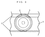
- FIG. 3 is a partial front view of the speaker device according to the first embodiment of the present invention.
- the structure of the speaker 1 is as such described above.
- the speaker device 1 As shown in FIG. 2 or 3, the speaker device 1 according to the first embodiment of the present invention is characterized by the shapes of the speaker baffle 4 and the fin 5, and the sound duct space 6 and the slots 7 both formed by the speaker baffle 4 and the fin 5.
- the fin 5 is provided forward of the speaker baffle 4 and opposed in parallel to a plane through which sound is outputted from the speaker 2.
- the surface of the fin 5 opposed to the speaker 2 is curved rearwardly so that the center portion of the fin 5 is closer to the speaker 2 than the upper and lower ends thereof.
- the fin 5 is typically has the cross-sectional profile as such that its upper and lower portions are thinner and its center is thicker when viewed from the side surface direction.
- the front surface of the fin 5 may take any form as long as the rear surface thereof facing to the speaker is shaped as described above.
- the front surface of the fin 5 may also be curved rearwardly so as to correspond to the curve of the rear surface.
- the fin 5 is formed with a plate of uniform thickness being bent.
- the shape of the front surface thereof may be flat parallel to the surface on which the Braun tube 10 is provided.
- the fin 5 viewed from the front has typically a rectangular shape, but may be an oval, circular, or any other shape. Therefore, for example, the front surface of the fin 5 may be circular, while its rear surface being rearwardly curved.
- the center portion of the fin 5 is positioned forward of the center of the speaker baffle 4. With the fin 5 positioned as such, the sound outputted from the speaker 2 is reflected on the curved surface of the fin 5. Part of the reflected sound is further reflected on the speaker baffle 4, and externally outputted from the slots 7.
- the sound space 6 is formed between the fin 5 and the speaker baffle 4, and the slots 7 opening outwardly from the sound space 6 are provided. It is assumed herein that the height of the fin 5 is slightly smaller than the diameter of the sound duct 3.
- FIG. 4 is a schematic diagram representing vertical sound dispersion from the speaker device according to the first embodiment of the present invention. Since simple sound sources can take the broadest directivity, the above-structured speaker device according to the present embodiment can take broad directivity.
- the slots 7 can be formed by spacing the fin 5 and the speaker baffle 4 a certain amount apart. Therefore, the height of the fin 5 is not limited to that described above in the present embodiment. However, if the height is smaller than the diameter of the sound duct 3, sound reflected by the fin 5 is reduced, and acoustic resistance and acoustic mass that affect high-range audio frequencies are accordingly reduced. Therefore, the present embodiment is preferable because the sound of high-range frequencies is sufficiently reproduced.
- the fin 5 may have one or more apertures penetrating through its surfaces.
- the position and size of the apertures are not limited, but preferably determined so as not to worsen the appearance of the speaker device. With such apertures on the fin 5, reflection by the fin 5 is reduced, and thereby acoustic resistance and acoustic mass that affect especially high-range frequencies can be reduced. As a result, the sound of high-range frequencies is sufficiently reproduced.
- the directivity becomes narrower as the total area of the apertures becomes too large. Therefore, the total area of the apertures is preferably determined so that the directivity can be broadened and the sound of high-range frequencies can be sufficiently reproduced.
- FIG. 5 is a schematic cross-sectional view of a speaker device according to a second embodiment of the present invention.
- FIG. 6 is a partial front view of the speaker device. Since having functions similar to those in FIG. 2, the components of the speaker device in the second embodiment are provided with the same reference numerals as those in FIG. 2, and only the difference from FIG. 2 will be described below.
- the fin 5 is at a position that avoids intersecting with an output center axis for the sound outputted from the speaker 2. Since the output center axis passes through the slot 7, the sound along the output center axis is directly outputted to the external. As shown in FIG. 6, if viewing from the front of the above-structured speaker device 1, the viewer can see, through the slot 7, a dust cap 8 formed at the center of a diaphragm of the speaker 2.
- the sound of high-range frequencies outputted from the center of the speaker 2 is directly outputted from the slot 7 to the external. Therefore, the sound can be outputted with high-frequency characteristics of the speaker unchanged.
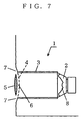
- FIG. 7 is a schematic diagram showing a speaker device according to a third embodiment of the present invention. Since having the functions similar to those in FIG. 2, the components shown in FIG. 7 are provided with the same reference numerals as those in FIG. 2, and only the difference from FIG. 2 will be described below.
- the fin 5 and the speaker baffle 4 are approximately evenly spaced apart so that the area of an opening rearward of the speaker baffle 4, that is, the area of an opening of the sound duct 3, becomes approximately equal to the total area of the slots 7 that correspond to the opening of the sound duct 3.
- Such structure approximately equalizes the values of acoustic resistance at the two slots 7 formed on the upper and lower sides of the fin 5, and thereby can stabilize the acoustic characteristics and phase. Furthermore, since the slots 7 are formed narrowly to make the sound source become analogous to a simple sound source, the directivity can be broadened.
- the above-described effects can be achieved when the fin 5 and the speaker baffle 4 are spaced apart so that that the area of the opening rearward of the speaker baffle 4, that is, the area of the opening of the sound duct 3, becomes approximately equal to the total area of the slots 7 that correspond to the opening of the sound duct 3.
- Graphs representing measurement results of the effects are shown in FIGS. 8A, 8B, 9A, and 9B. Considered below are the results shown in these drawings and the reasons therefor.
- FIGS. 8A, 8B, 9A, and 9B are graphs showing how the acoustic characteristics of the speaker device are changed as the distance between the fin 5 and the speaker baffle 4 is changed. Note that the distance referred herein is between the rear end of the fin 5 and the opening of the speaker baffle 4 on the sound output center axis.
- the diameter of a sound duct in a speaker device used for measurement is 44 mm; the length of the sound duct is 270 mm; and the voluminous capacity of the sound duct is 0.3 litter.
- the distance between the fin 5 and the speaker baffle 4 is 0 mm in FIG. 8A; 5 mm in FIG. 8B; 10 mm in FIG. 9A; and 15 mm in FIG. 9B.
- the acoustic characteristics of the speaker device are measured , and represented by the graphs of these drawings with sound pressure (dB) as the vertical axis and frequency (Hz) as the horizontal axis.
- the measurement values are represented by shaded bars. Slightly large blank bars superimposed thereon indicate values measured with the fin 5 removed. This allows easy comparison of degradation in acoustic characteristics.
- the fin 5 and the speaker baffle 4 are spaced 0 mm apart, significant degradation in acoustic characteristics is observed in high and mid-range frequencies, particularly in high-range frequencies.
- the reason for this degradation can be assumed as follows: If the opening of the sound duct is closed with the fin 5, the sound duct becomes a tube with both ends closed. As a result, the sound duct becomes like a speaker enclosure with a given capacity. Therefore, the opening of the sound duct serves as a low-pass filter that does not lend itself to passing high- and mid-range frequencies, just like a bass-reflex port of a speaker enclosure.
- the acoustic characteristics in high- and mid-range frequencies are slightly improved.
- the reason for this improvement can be assumed as follows: The fin 5 does not close the opening of the sound duct, but is isolated therefrom. Therefore, the acoustic resistance and acoustic mass can be reduced. Such reduction diminishes the effects of the low-pass filter.
- the acoustic characteristics become slightly degraded. Although the characteristics become less degraded as the total area of slots 7 becomes larger, the directivity becomes narrow if the slots 7 become too large. That may be the reason for this slight degradation.
- the slots 7 are formed narrowly, the sound source becomes analogous to a simple sound source, thereby allowing broad directivity. If the slots 7 are formed broadly, however, the directivity becomes narrower. It can thus be thought that the acoustic characteristics outside the narrowed directivity become degraded. Therefore, if the distance is 10 mm, the area of the opening rearward of the speaker baffle 4, that is, the area of the opening of the sound duct 3, becomes approximately equal to the total area of the slots 7 that correspond to the opening of the sound duct 3. Therefore, the acoustic characteristics can be maximized with broad directivity and reduced effects of air viscous drag.
- the fin 5 in FIG. 7 is similar to that in FIG. 2, the fin 5 may be in a shape as shown in FIG. 10A or 10B, or another shape.
- the position of the fin 5 is also not limited to that as shown in FIG. 2.
- FIGS. 10A and 10B are schematic diagrams each showing a speaker device according to a fourth embodiment of the present invention. Since having functions similar to those in FIG. 2, the components shown in FIGS. 10A and 10B are provided with the same reference numerals as those in FIG. 2, and only the difference from FIG. 2 will be described below.
- FIGS. 10A and 10B are cross-sectional views of the speaker device 1 taken from the side surface of the television.
- the surface of the fin 5 opposed to the speaker 2 is curved rearwardly so that the center portion of the fin 5 is closer in position to the speaker 2 than both upper and lower ends thereof.
- the center portion on the rear of the fin 5 extends toward and beyond the corresponding speaker baffle 4, reaching inside of the sound duct 3.
- the cross section of the fin 5 viewed from the side surface of the television is a semicircle, as shown in FIG. 10A.
- FIG. 10B similarly to FIG. 10A, the surface of the fin 5 opposed to the speaker 2 is curved rearwardly so that the center portion of the fin 5 is closer in position to the speaker 2 than both upper and lower ends thereof.
- FIG. 10B is different from FIG. 10A, however, in that the cross section of the fin 5 viewed from the side surface of the television is in a triangular shape.
- the acoustic resistance due to air viscous drag becomes small, the acoustic characteristics is improved.
- the acoustic resistance becomes larger as the angle of the surface of the fin 5 reflecting sound becomes closer to be vertical with respect to a sound output direction. Therefore, the shape of the fin 5 is so formed as that the center portion on the rear of the fin 5 extends toward and beyond the center portion of the corresponding speaker baffle 4 to reach inside of the sound duct 3.
- the angle which the surface of the fin 5 forms with the direction of sound outputted from the speaker 2 becomes small, thereby allowing reduction in acoustic resistance and improvement in acoustic characteristics of the speaker device 1.
- the slots 7 become narrow and the sound source becomes analogous to a simple point source. Therefore, similarly to the speaker device according to the first embodiment, the directivity can be broadened.
- FIG. 11 is a diagram showing the structure of speaker devices according to a fifth embodiment of the present invention, and a television including such speaker device. Since having the same functions as those in FIG. 1, the components shown in FIG. 11 are provided with the same reference numerals as those in FIG. 1, and only the difference from FIG. 1 will be described below.
- the television in FIG. 11 is different from that in FIG. 1 in that high-frequency speaker devices 14 are provided.
- the high-frequency speaker devices 14 are provided on the front-right and front-left of the television box 11, and the fin 5 is provided forward of each of the high-frequency speaker devices 14.
- the speaker devices 1 are provided on either upper-front or lower-front portions of the television box 11, the acoustic image can be placed in the vicinity of the center of the screen.
- the directivity in high-range frequencies can be broadened in the horizontal direction. Therefore, the listener can feel the sound spreading more.
- the high-frequency speaker device 14 may be dedicated to be used for high-range frequencies, or generally for high-range but not excluding mid-range frequencies. Also, the high-frequency speaker device 14 may be a speaker device for any frequency range, as the speaker 1. In such case, the directivity in the horizontal direction can be broadened over the entire frequency range, and therefore the listener can feel the sound spreading more.
- FIG. 12 is a schematic diagram showing vertical sound dispersion from the speaker device 1 and the high-frequency speaker device 14. As shown in FIG. 12, even if the speaker device 1 is provided on the lower-front of the television box 11, the acoustic image can be placed in the vicinity of the center of the screen.
- FIG. 13 is a diagram showing the structure of speaker devices according to a sixth embodiment of the present invention, and a television including such speaker device. Since having the same functions as those in FIG. 11, the components shown in FIG. 12 are provided with the same reference numerals as those in FIG. 11, and only the difference from FIG. 11 will be described below.
- the television in FIG. 12 is different from that in FIG. 11 in that the fin 5 is not provided forward of each of the high-frequency speaker devices 14.
- FIG. 13 shows the structure that the slots 7 for the high-frequency speaker devices 14 are provided on the front-right and front-left of the television box 11 and the right and left side surfaces thereof.
- the high-frequency speaker devices 14 are provided on the right and left of the television box 11.
- the slots 6 for the high-frequency speaker devices 14 are provided either on the front-right and front-left or on the right and left sides, or both, of the television box 11. With such structure, the slots 7 can be visually simplified. Therefore, the width of the front surface of the television with the width of its screen subtracted therefrom can be reduced.
- the directivity in high-range frequencies can be broadened in the horizontal direction. Therefore, the listener can feel the sound spreading more.
- the speaker devices are applied to a television.
- the speaker device according to each of the above embodiments may also be applied to video equipment such as a display monitor and personal computer.
Landscapes
- Physics & Mathematics (AREA)
- Engineering & Computer Science (AREA)
- Acoustics & Sound (AREA)
- Signal Processing (AREA)
- Obtaining Desirable Characteristics In Audible-Bandwidth Transducers (AREA)
- Details Of Audible-Bandwidth Transducers (AREA)
Abstract
Description
Therefore, if the distance is 10 mm, the area of the opening rearward of the
Claims (13)
- A video equipment speaker device (1) having an acoustic lens; comprising:a speaker (2) for forwardly outputting sound;a speaker baffle (4) provided forward of said speaker (2) with an opening through which the outputted sound passes; anda fin (5), as said acoustic lens, opposed to said speaker (2) so as to form slits (7) for sound passage with said speaker baffle (4), and having a shape in cross section as such that a center portion of a surface opposed to said speaker (2) is rearwardly curved, whereinthe sound outputted from said speaker (2) passes through said slit (7) and reflects between said fin (5) and said speaker baffle (4) to be externally outputted from said slits.
- The video equipment speaker device (1) according to claim 1, whereinsaid fin (5) has a shape so that the opening of said speaker baffle (4) is not entirely covered when viewed from the front of said video equipment (11).
- The video equipment speaker device (1) according to claim 2, whereinsaid fin (5) is provided at a position that avoids intersecting with a center axis for sound outputted from said speaker (2).
- The video equipment speaker device (1) according to claim 3, whereinsaid center axis passes through one of said slits (7) formed between said fin (5) and said speaker baffle (4), andpart of the sound outputted from said speaker (2) is directly outputted from said slit (7).
- The video equipment speaker device (1) according to claim 1, whereinsaid fin (5) is in a rectangular shape when viewed from the front of said video equipment (11).
- The video equipment speaker device (1) according to claim 1, whereinsaid fin (5) has one or more apertures, andpart of the sound outputted from said speaker (2) is externally outputted through the apertures.
- The video equipment speaker device (1) according to claim 1, whereina total area of the slits (7) between said fin (5) and said speaker baffle (4) that correspond to the opening of said speaker baffle (4) is approximately equal to an area of the opening of said speaker baffle (4).
- The video equipment speaker device (1) according to claim 1, whereinthe center portion of the rearwardly-curved surface of said fin (5) is positioned closer to said speaker (2) through the opening of said speaker baffle (4).
- The video equipment speaker device (1) according to claim 1, whereinsaid speaker device (1) is provided on an upper-front and/or lower-front of said video equipment (11).
- The video equipment speaker device (1) according to claim 1, whereinsaid speaker devices (1) are provided on front-right and front-left of said video equipment (11).
- The video equipment speaker device (1) according to claim 1, whereinsaid speaker devices (1) are provided on upper-front and/or lower-front and front-right and front-left of said video equipment (11).
- The video equipment speaker device (1) according to claim 11, whereinsaid speaker devices (1) provided on the front-right and front-left of said video equipment (11) are dedicatedly used for high-range frequencies.
- A video unit (11) comprising a video unit box that accommodates a video unit circuit set, first speaker devices (1) provided on upper-front and/or lower-front of the video unit box, and second speaker devices (14) provided on front-right and front-left of the video unit box and dedicatedly used for high-range frequencies,each of said first speaker devices (1) comprising:a speaker (2) for forwardly outputting sound;a speaker baffle (4) provided forward of said speaker (2) with an opening through which the outputted sound passes; anda fin (5) opposed to said speaker (2) so as to form slits (7) for sound passage with said speaker baffle (4), and having a shape in cross section as such that a center portion of a surface opposed to said speaker (2) is rearwardly curved, whereinthe sound outputted from said speaker (2) passes through said opening and reflects between said fin (5) and said speaker baffle (4) to be externally outputted from said slits (7).
Applications Claiming Priority (2)
| Application Number | Priority Date | Filing Date | Title |
|---|---|---|---|
| JP19214699 | 1999-07-06 | ||
| JP11192146A JP2001025080A (en) | 1999-07-06 | 1999-07-06 | Speaker device with acoustic lens for video equipment |
Publications (2)
| Publication Number | Publication Date |
|---|---|
| EP1067818A2 true EP1067818A2 (en) | 2001-01-10 |
| EP1067818A3 EP1067818A3 (en) | 2004-06-30 |
Family
ID=16286473
Family Applications (1)
| Application Number | Title | Priority Date | Filing Date |
|---|---|---|---|
| EP00114010A Withdrawn EP1067818A3 (en) | 1999-07-06 | 2000-07-04 | Video equipment speaker device with acoustic lens |
Country Status (7)
| Country | Link |
|---|---|
| US (1) | US6533063B1 (en) |
| EP (1) | EP1067818A3 (en) |
| JP (1) | JP2001025080A (en) |
| CN (1) | CN1157057C (en) |
| CA (1) | CA2313423A1 (en) |
| MY (1) | MY126940A (en) |
| SG (1) | SG92718A1 (en) |
Cited By (1)
| Publication number | Priority date | Publication date | Assignee | Title |
|---|---|---|---|---|
| WO2011067060A1 (en) | 2009-12-02 | 2011-06-09 | Fraunhofer-Gesellschaft zur Förderung der angewandten Forschung e.V. | Flat loudspeaker |
Families Citing this family (8)
| Publication number | Priority date | Publication date | Assignee | Title |
|---|---|---|---|---|
| JP4523739B2 (en) * | 2001-07-13 | 2010-08-11 | ローランド株式会社 | Speaker device |
| JP2003274314A (en) * | 2002-03-13 | 2003-09-26 | Seiko Epson Corp | Rear projector and method of manufacturing the same |
| JP4427763B2 (en) * | 2007-12-10 | 2010-03-10 | ソニー株式会社 | display |
| WO2009078164A1 (en) * | 2007-12-18 | 2009-06-25 | Panasonic Corporation | Speaker device having directivity adjustment panel |
| BRPI0917410A2 (en) | 2008-08-14 | 2015-12-01 | Harman Int Ind | phase cap and acoustic lens for direct radiation speaker |
| KR102023189B1 (en) * | 2013-07-03 | 2019-09-20 | 삼성전자주식회사 | Sound generation apparatus and electric apparatus comprising thereof |
| WO2017030914A1 (en) | 2015-08-14 | 2017-02-23 | Dolby Laboratories Licensing Corporation | Upward firing loudspeaker having asymmetric dispersion for reflected sound rendering |
| JPWO2020137177A1 (en) * | 2018-12-26 | 2021-11-18 | ソニーグループ株式会社 | Display device |
Family Cites Families (11)
| Publication number | Priority date | Publication date | Assignee | Title |
|---|---|---|---|---|
| NL267133A (en) | 1960-07-15 | |||
| GB1572024A (en) * | 1977-05-06 | 1980-07-23 | Tannoy Products Ltd | Moving coil loudspeakers |
| US4844198A (en) * | 1988-04-07 | 1989-07-04 | Ferralli Michael W | Plane wave focusing lens |
| DE3933170C2 (en) * | 1989-10-04 | 1994-11-10 | Arthur Pfister | Device for generating a stereo-like sound reproduction |
| JP3104073B2 (en) | 1990-12-22 | 2000-10-30 | ソニー株式会社 | Speaker device of television receiver |
| JPH05236583A (en) | 1992-02-20 | 1993-09-10 | Toshiba Corp | Speaker system |
| JP3267999B2 (en) | 1992-02-20 | 2002-03-25 | 株式会社東芝 | Speaker system |
| JPH0635489A (en) * | 1992-07-21 | 1994-02-10 | Mitsubishi Electric Corp | Speaker device for TV |
| US5627901A (en) * | 1993-06-23 | 1997-05-06 | Apple Computer, Inc. | Directional microphone for computer visual display monitor and method for construction |
| US6031920A (en) * | 1997-05-16 | 2000-02-29 | Wiener; David | Coaxial dual-parabolic sound lens speaker system |
| US6134332A (en) * | 1997-05-16 | 2000-10-17 | Wiener; David | Sound lens speaker system |
-
1999
- 1999-07-06 JP JP11192146A patent/JP2001025080A/en active Pending
-
2000
- 2000-07-04 MY MYPI20003048 patent/MY126940A/en unknown
- 2000-07-04 EP EP00114010A patent/EP1067818A3/en not_active Withdrawn
- 2000-07-05 CA CA002313423A patent/CA2313423A1/en not_active Abandoned
- 2000-07-05 SG SG200003749A patent/SG92718A1/en unknown
- 2000-07-05 US US09/610,359 patent/US6533063B1/en not_active Expired - Fee Related
- 2000-07-06 CN CNB001203355A patent/CN1157057C/en not_active Expired - Fee Related
Cited By (3)
| Publication number | Priority date | Publication date | Assignee | Title |
|---|---|---|---|---|
| WO2011067060A1 (en) | 2009-12-02 | 2011-06-09 | Fraunhofer-Gesellschaft zur Förderung der angewandten Forschung e.V. | Flat loudspeaker |
| US8798302B2 (en) | 2009-12-02 | 2014-08-05 | Fraunhofer-Gesellschaft Zur Foerderung Der Angewandten Forschung E.V. | Flat panel loudspeakers |
| KR101479823B1 (en) | 2009-12-02 | 2015-01-06 | 프라운호퍼 게젤샤프트 쭈르 푀르데룽 데어 안겐반텐 포르슝 에. 베. | Flat loudspeaker |
Also Published As
| Publication number | Publication date |
|---|---|
| CN1279561A (en) | 2001-01-10 |
| SG92718A1 (en) | 2002-11-19 |
| EP1067818A3 (en) | 2004-06-30 |
| MY126940A (en) | 2006-11-30 |
| CN1157057C (en) | 2004-07-07 |
| JP2001025080A (en) | 2001-01-26 |
| CA2313423A1 (en) | 2001-01-06 |
| US6533063B1 (en) | 2003-03-18 |
Similar Documents
| Publication | Publication Date | Title |
|---|---|---|
| US7280665B2 (en) | Image display device with built-in loudspeakers | |
| CN108235193B (en) | Directional speaker and display apparatus having the same | |
| EP0659030B1 (en) | Speaker system for television sets | |
| JP3449571B2 (en) | TV set speaker system | |
| CN107925826B (en) | Speaker device and electronic device including the same | |
| US6533063B1 (en) | Video equipment speaker device with acoustic lens | |
| CN108476360B (en) | Loudspeaker device or system with controlled sound field | |
| JPH06105257A (en) | Speaker for television receiver | |
| US10499141B2 (en) | Wideband slot-loading loudspeaker | |
| US12439201B2 (en) | Narrow aperture waveguide loudspeaker for use with flat panel display devices | |
| US20090046875A1 (en) | Speaker device | |
| JP2009038446A (en) | Speaker box structure and thin display device equipped with the speaker box | |
| US11647323B2 (en) | Loudspeaker | |
| TW200401576A (en) | Bass reflex type speaker device, mounting structure and mounting method for speaker device | |
| EP3585066B1 (en) | Acoustic lens and speaker system | |
| US20250063298A1 (en) | Directivity pattern control waveguide for a speaker, and speaker including a directivity pattern control waveguide | |
| KR102564275B1 (en) | Speaker and electronic apparatus having the same | |
| CN107710782A (en) | Speaker system, display device and television receiver | |
| JP2011087146A (en) | Display device with speaker | |
| JP2018007221A (en) | Speaker system | |
| WO2005096665A1 (en) | Distributed acoustic cabinet | |
| CN107517355B (en) | Television set | |
| CN215815114U (en) | Display device | |
| JP2018129685A (en) | Display unit and television receiver | |
| JP2018129686A (en) | Woofer box, display device, and television receiver |
Legal Events
| Date | Code | Title | Description |
|---|---|---|---|
| PUAI | Public reference made under article 153(3) epc to a published international application that has entered the european phase |
Free format text: ORIGINAL CODE: 0009012 |
|
| AK | Designated contracting states |
Kind code of ref document: A2 Designated state(s): AT BE CH CY DE DK ES FI FR GB GR IE IT LI LU MC NL PT SE |
|
| AX | Request for extension of the european patent |
Free format text: AL;LT;LV;MK;RO;SI |
|
| PUAL | Search report despatched |
Free format text: ORIGINAL CODE: 0009013 |
|
| AK | Designated contracting states |
Kind code of ref document: A3 Designated state(s): AT BE CH CY DE DK ES FI FR GB GR IE IT LI LU MC NL PT SE |
|
| AX | Request for extension of the european patent |
Extension state: AL LT LV MK RO SI |
|
| RIC1 | Information provided on ipc code assigned before grant |
Ipc: 7H 04R 1/34 B Ipc: 7H 04R 5/02 A |
|
| 17P | Request for examination filed |
Effective date: 20040903 |
|
| AKX | Designation fees paid |
Designated state(s): DE FR GB IT |
|
| 17Q | First examination report despatched |
Effective date: 20071106 |
|
| STAA | Information on the status of an ep patent application or granted ep patent |
Free format text: STATUS: THE APPLICATION IS DEEMED TO BE WITHDRAWN |
|
| 18D | Application deemed to be withdrawn |
Effective date: 20080318 |