EP1070534B1 - Procede de fabrication d'un filtre comportant un film poreux ceramique comme film de separation - Google Patents
Procede de fabrication d'un filtre comportant un film poreux ceramique comme film de separation Download PDFInfo
- Publication number
- EP1070534B1 EP1070534B1 EP00902025A EP00902025A EP1070534B1 EP 1070534 B1 EP1070534 B1 EP 1070534B1 EP 00902025 A EP00902025 A EP 00902025A EP 00902025 A EP00902025 A EP 00902025A EP 1070534 B1 EP1070534 B1 EP 1070534B1
- Authority
- EP
- European Patent Office
- Prior art keywords
- micro
- pore size
- substrate
- film
- slurry
- Prior art date
- Legal status (The legal status is an assumption and is not a legal conclusion. Google has not performed a legal analysis and makes no representation as to the accuracy of the status listed.)
- Expired - Lifetime
Links
- 238000000034 method Methods 0.000 title claims description 27
- 239000000919 ceramic Substances 0.000 title claims description 21
- 238000004519 manufacturing process Methods 0.000 title claims description 15
- 239000002245 particle Substances 0.000 claims description 92
- 239000000758 substrate Substances 0.000 claims description 65
- 239000012528 membrane Substances 0.000 claims description 59
- 238000000151 deposition Methods 0.000 claims description 58
- 239000002002 slurry Substances 0.000 claims description 54
- 230000008021 deposition Effects 0.000 claims description 29
- 238000000926 separation method Methods 0.000 claims description 21
- 229920001817 Agar Polymers 0.000 claims description 18
- 239000008272 agar Substances 0.000 claims description 18
- 239000000203 mixture Substances 0.000 claims description 11
- 229920002310 Welan gum Polymers 0.000 claims description 10
- 229920000620 organic polymer Polymers 0.000 claims description 10
- 229920000178 Acrylic resin Polymers 0.000 claims description 8
- 239000004925 Acrylic resin Substances 0.000 claims description 8
- 239000002202 Polyethylene glycol Substances 0.000 claims description 4
- 229920001223 polyethylene glycol Polymers 0.000 claims description 4
- 239000004372 Polyvinyl alcohol Substances 0.000 claims description 3
- 229920002451 polyvinyl alcohol Polymers 0.000 claims description 3
- 150000001720 carbohydrates Chemical class 0.000 claims description 2
- 239000002861 polymer material Substances 0.000 claims 3
- 239000011148 porous material Substances 0.000 description 89
- 239000010408 film Substances 0.000 description 67
- 238000001914 filtration Methods 0.000 description 43
- 239000003795 chemical substances by application Substances 0.000 description 28
- XLYOFNOQVPJJNP-UHFFFAOYSA-N water Substances O XLYOFNOQVPJJNP-UHFFFAOYSA-N 0.000 description 20
- GWEVSGVZZGPLCZ-UHFFFAOYSA-N Titan oxide Chemical compound O=[Ti]=O GWEVSGVZZGPLCZ-UHFFFAOYSA-N 0.000 description 14
- 238000010304 firing Methods 0.000 description 12
- 238000002360 preparation method Methods 0.000 description 12
- PNEYBMLMFCGWSK-UHFFFAOYSA-N aluminium oxide Inorganic materials [O-2].[O-2].[O-2].[Al+3].[Al+3] PNEYBMLMFCGWSK-UHFFFAOYSA-N 0.000 description 11
- 238000007598 dipping method Methods 0.000 description 11
- MCMNRKCIXSYSNV-UHFFFAOYSA-N Zirconium dioxide Chemical compound O=[Zr]=O MCMNRKCIXSYSNV-UHFFFAOYSA-N 0.000 description 6
- 230000000052 comparative effect Effects 0.000 description 5
- WQZGKKKJIJFFOK-GASJEMHNSA-N Glucose Natural products OC[C@H]1OC(O)[C@H](O)[C@@H](O)[C@@H]1O WQZGKKKJIJFFOK-GASJEMHNSA-N 0.000 description 4
- VYPSYNLAJGMNEJ-UHFFFAOYSA-N Silicium dioxide Chemical compound O=[Si]=O VYPSYNLAJGMNEJ-UHFFFAOYSA-N 0.000 description 4
- 238000009826 distribution Methods 0.000 description 4
- 239000008103 glucose Substances 0.000 description 4
- 239000007788 liquid Substances 0.000 description 4
- 239000000463 material Substances 0.000 description 4
- 229920000642 polymer Polymers 0.000 description 4
- VZSRBBMJRBPUNF-UHFFFAOYSA-N 2-(2,3-dihydro-1H-inden-2-ylamino)-N-[3-oxo-3-(2,4,6,7-tetrahydrotriazolo[4,5-c]pyridin-5-yl)propyl]pyrimidine-5-carboxamide Chemical compound C1C(CC2=CC=CC=C12)NC1=NC=C(C=N1)C(=O)NCCC(N1CC2=C(CC1)NN=N2)=O VZSRBBMJRBPUNF-UHFFFAOYSA-N 0.000 description 3
- 239000007864 aqueous solution Substances 0.000 description 3
- 239000011230 binding agent Substances 0.000 description 3
- 230000007547 defect Effects 0.000 description 3
- 238000001035 drying Methods 0.000 description 3
- 230000000694 effects Effects 0.000 description 3
- 150000004676 glycans Chemical class 0.000 description 3
- 238000010438 heat treatment Methods 0.000 description 3
- 238000002347 injection Methods 0.000 description 3
- 239000007924 injection Substances 0.000 description 3
- QSHDDOUJBYECFT-UHFFFAOYSA-N mercury Chemical compound [Hg] QSHDDOUJBYECFT-UHFFFAOYSA-N 0.000 description 3
- 229910052753 mercury Inorganic materials 0.000 description 3
- 229920001282 polysaccharide Polymers 0.000 description 3
- 239000005017 polysaccharide Substances 0.000 description 3
- 239000000843 powder Substances 0.000 description 3
- YIWGJFPJRAEKMK-UHFFFAOYSA-N 1-(2H-benzotriazol-5-yl)-3-methyl-8-[2-[[3-(trifluoromethoxy)phenyl]methylamino]pyrimidine-5-carbonyl]-1,3,8-triazaspiro[4.5]decane-2,4-dione Chemical compound CN1C(=O)N(c2ccc3n[nH]nc3c2)C2(CCN(CC2)C(=O)c2cnc(NCc3cccc(OC(F)(F)F)c3)nc2)C1=O YIWGJFPJRAEKMK-UHFFFAOYSA-N 0.000 description 2
- OKTJSMMVPCPJKN-UHFFFAOYSA-N Carbon Chemical compound [C] OKTJSMMVPCPJKN-UHFFFAOYSA-N 0.000 description 2
- SHZGCJCMOBCMKK-UHFFFAOYSA-N D-mannomethylose Natural products CC1OC(O)C(O)C(O)C1O SHZGCJCMOBCMKK-UHFFFAOYSA-N 0.000 description 2
- IAJILQKETJEXLJ-UHFFFAOYSA-N Galacturonsaeure Natural products O=CC(O)C(O)C(O)C(O)C(O)=O IAJILQKETJEXLJ-UHFFFAOYSA-N 0.000 description 2
- SHZGCJCMOBCMKK-JFNONXLTSA-N L-rhamnopyranose Chemical compound C[C@@H]1OC(O)[C@H](O)[C@H](O)[C@H]1O SHZGCJCMOBCMKK-JFNONXLTSA-N 0.000 description 2
- PNNNRSAQSRJVSB-UHFFFAOYSA-N L-rhamnose Natural products CC(O)C(O)C(O)C(O)C=O PNNNRSAQSRJVSB-UHFFFAOYSA-N 0.000 description 2
- NIPNSKYNPDTRPC-UHFFFAOYSA-N N-[2-oxo-2-(2,4,6,7-tetrahydrotriazolo[4,5-c]pyridin-5-yl)ethyl]-2-[[3-(trifluoromethoxy)phenyl]methylamino]pyrimidine-5-carboxamide Chemical compound O=C(CNC(=O)C=1C=NC(=NC=1)NCC1=CC(=CC=C1)OC(F)(F)F)N1CC2=C(CC1)NN=N2 NIPNSKYNPDTRPC-UHFFFAOYSA-N 0.000 description 2
- AFCARXCZXQIEQB-UHFFFAOYSA-N N-[3-oxo-3-(2,4,6,7-tetrahydrotriazolo[4,5-c]pyridin-5-yl)propyl]-2-[[3-(trifluoromethoxy)phenyl]methylamino]pyrimidine-5-carboxamide Chemical compound O=C(CCNC(=O)C=1C=NC(=NC=1)NCC1=CC(=CC=C1)OC(F)(F)F)N1CC2=C(CC1)NN=N2 AFCARXCZXQIEQB-UHFFFAOYSA-N 0.000 description 2
- RTAQQCXQSZGOHL-UHFFFAOYSA-N Titanium Chemical compound [Ti] RTAQQCXQSZGOHL-UHFFFAOYSA-N 0.000 description 2
- JAWMENYCRQKKJY-UHFFFAOYSA-N [3-(2,4,6,7-tetrahydrotriazolo[4,5-c]pyridin-5-ylmethyl)-1-oxa-2,8-diazaspiro[4.5]dec-2-en-8-yl]-[2-[[3-(trifluoromethoxy)phenyl]methylamino]pyrimidin-5-yl]methanone Chemical compound N1N=NC=2CN(CCC=21)CC1=NOC2(C1)CCN(CC2)C(=O)C=1C=NC(=NC=1)NCC1=CC(=CC=C1)OC(F)(F)F JAWMENYCRQKKJY-UHFFFAOYSA-N 0.000 description 2
- IAJILQKETJEXLJ-QTBDOELSSA-N aldehydo-D-glucuronic acid Chemical compound O=C[C@H](O)[C@@H](O)[C@H](O)[C@H](O)C(O)=O IAJILQKETJEXLJ-QTBDOELSSA-N 0.000 description 2
- 229910052799 carbon Inorganic materials 0.000 description 2
- 230000007797 corrosion Effects 0.000 description 2
- 238000005260 corrosion Methods 0.000 description 2
- KZHJGOXRZJKJNY-UHFFFAOYSA-N dioxosilane;oxo(oxoalumanyloxy)alumane Chemical compound O=[Si]=O.O=[Si]=O.O=[Al]O[Al]=O.O=[Al]O[Al]=O.O=[Al]O[Al]=O KZHJGOXRZJKJNY-UHFFFAOYSA-N 0.000 description 2
- 238000011156 evaluation Methods 0.000 description 2
- 229940097043 glucuronic acid Drugs 0.000 description 2
- 239000010410 layer Substances 0.000 description 2
- 239000011259 mixed solution Substances 0.000 description 2
- 238000002156 mixing Methods 0.000 description 2
- 229910052863 mullite Inorganic materials 0.000 description 2
- 238000002203 pretreatment Methods 0.000 description 2
- 239000000377 silicon dioxide Substances 0.000 description 2
- 239000007858 starting material Substances 0.000 description 2
- 239000000126 substance Substances 0.000 description 2
- 229910052719 titanium Inorganic materials 0.000 description 2
- 239000010936 titanium Substances 0.000 description 2
- SMZOUWXMTYCWNB-UHFFFAOYSA-N 2-(2-methoxy-5-methylphenyl)ethanamine Chemical compound COC1=CC=C(C)C=C1CCN SMZOUWXMTYCWNB-UHFFFAOYSA-N 0.000 description 1
- NIXOWILDQLNWCW-UHFFFAOYSA-N 2-Propenoic acid Natural products OC(=O)C=C NIXOWILDQLNWCW-UHFFFAOYSA-N 0.000 description 1
- YLZOPXRUQYQQID-UHFFFAOYSA-N 3-(2,4,6,7-tetrahydrotriazolo[4,5-c]pyridin-5-yl)-1-[4-[2-[[3-(trifluoromethoxy)phenyl]methylamino]pyrimidin-5-yl]piperazin-1-yl]propan-1-one Chemical compound N1N=NC=2CN(CCC=21)CCC(=O)N1CCN(CC1)C=1C=NC(=NC=1)NCC1=CC(=CC=C1)OC(F)(F)F YLZOPXRUQYQQID-UHFFFAOYSA-N 0.000 description 1
- WQZGKKKJIJFFOK-QTVWNMPRSA-N D-mannopyranose Chemical compound OC[C@H]1OC(O)[C@@H](O)[C@@H](O)[C@@H]1O WQZGKKKJIJFFOK-QTVWNMPRSA-N 0.000 description 1
- MKYBYDHXWVHEJW-UHFFFAOYSA-N N-[1-oxo-1-(2,4,6,7-tetrahydrotriazolo[4,5-c]pyridin-5-yl)propan-2-yl]-2-[[3-(trifluoromethoxy)phenyl]methylamino]pyrimidine-5-carboxamide Chemical compound O=C(C(C)NC(=O)C=1C=NC(=NC=1)NCC1=CC(=CC=C1)OC(F)(F)F)N1CC2=C(CC1)NN=N2 MKYBYDHXWVHEJW-UHFFFAOYSA-N 0.000 description 1
- VCUFZILGIRCDQQ-KRWDZBQOSA-N N-[[(5S)-2-oxo-3-(2-oxo-3H-1,3-benzoxazol-6-yl)-1,3-oxazolidin-5-yl]methyl]-2-[[3-(trifluoromethoxy)phenyl]methylamino]pyrimidine-5-carboxamide Chemical compound O=C1O[C@H](CN1C1=CC2=C(NC(O2)=O)C=C1)CNC(=O)C=1C=NC(=NC=1)NCC1=CC(=CC=C1)OC(F)(F)F VCUFZILGIRCDQQ-KRWDZBQOSA-N 0.000 description 1
- GRYLNZFGIOXLOG-UHFFFAOYSA-N Nitric acid Chemical compound O[N+]([O-])=O GRYLNZFGIOXLOG-UHFFFAOYSA-N 0.000 description 1
- 229920003171 Poly (ethylene oxide) Polymers 0.000 description 1
- 239000002253 acid Substances 0.000 description 1
- 239000000654 additive Substances 0.000 description 1
- 239000003513 alkali Substances 0.000 description 1
- HSFWRNGVRCDJHI-UHFFFAOYSA-N alpha-acetylene Natural products C#C HSFWRNGVRCDJHI-UHFFFAOYSA-N 0.000 description 1
- WQZGKKKJIJFFOK-VFUOTHLCSA-N beta-D-glucose Chemical compound OC[C@H]1O[C@@H](O)[C@H](O)[C@@H](O)[C@@H]1O WQZGKKKJIJFFOK-VFUOTHLCSA-N 0.000 description 1
- 230000005540 biological transmission Effects 0.000 description 1
- 230000015572 biosynthetic process Effects 0.000 description 1
- 230000015556 catabolic process Effects 0.000 description 1
- 239000001913 cellulose Substances 0.000 description 1
- 229920002678 cellulose Polymers 0.000 description 1
- 238000004140 cleaning Methods 0.000 description 1
- 150000001875 compounds Chemical class 0.000 description 1
- 238000006731 degradation reaction Methods 0.000 description 1
- 239000002270 dispersing agent Substances 0.000 description 1
- 239000006185 dispersion Substances 0.000 description 1
- 239000000839 emulsion Substances 0.000 description 1
- 238000010559 graft polymerization reaction Methods 0.000 description 1
- 239000011229 interlayer Substances 0.000 description 1
- 229910052751 metal Inorganic materials 0.000 description 1
- 239000002184 metal Substances 0.000 description 1
- 229910044991 metal oxide Inorganic materials 0.000 description 1
- 150000004706 metal oxides Chemical class 0.000 description 1
- 239000000178 monomer Substances 0.000 description 1
- 150000002772 monosaccharides Chemical class 0.000 description 1
- 229910017604 nitric acid Inorganic materials 0.000 description 1
- 230000001590 oxidative effect Effects 0.000 description 1
- CMOAHYOGLLEOGO-UHFFFAOYSA-N oxozirconium;dihydrochloride Chemical compound Cl.Cl.[Zr]=O CMOAHYOGLLEOGO-UHFFFAOYSA-N 0.000 description 1
- 239000012466 permeate Substances 0.000 description 1
- 229920000090 poly(aryl ether) Polymers 0.000 description 1
- -1 polyacenaphthylene Polymers 0.000 description 1
- 229920001197 polyacetylene Polymers 0.000 description 1
- 229920002239 polyacrylonitrile Polymers 0.000 description 1
- 229920005597 polymer membrane Polymers 0.000 description 1
- 238000001556 precipitation Methods 0.000 description 1
- 230000003449 preventive effect Effects 0.000 description 1
- 239000003870 refractory metal Substances 0.000 description 1
- 239000011347 resin Substances 0.000 description 1
- 229920005989 resin Polymers 0.000 description 1
- 238000005245 sintering Methods 0.000 description 1
- 239000007787 solid Substances 0.000 description 1
- 239000000243 solution Substances 0.000 description 1
- 229910052596 spinel Inorganic materials 0.000 description 1
- 239000011029 spinel Substances 0.000 description 1
- 239000010409 thin film Substances 0.000 description 1
- XREXPQGDOPQPAH-QKUPJAQQSA-K trisodium;[(z)-18-[1,3-bis[[(z)-12-sulfonatooxyoctadec-9-enoyl]oxy]propan-2-yloxy]-18-oxooctadec-9-en-7-yl] sulfate Chemical compound [Na+].[Na+].[Na+].CCCCCCC(OS([O-])(=O)=O)C\C=C/CCCCCCCC(=O)OCC(OC(=O)CCCCCCC\C=C/CC(CCCCCC)OS([O-])(=O)=O)COC(=O)CCCCCCC\C=C/CC(CCCCCC)OS([O-])(=O)=O XREXPQGDOPQPAH-QKUPJAQQSA-K 0.000 description 1
- 238000009849 vacuum degassing Methods 0.000 description 1
- 239000011800 void material Substances 0.000 description 1
Images


Classifications
-
- B—PERFORMING OPERATIONS; TRANSPORTING
- B01—PHYSICAL OR CHEMICAL PROCESSES OR APPARATUS IN GENERAL
- B01D—SEPARATION
- B01D67/00—Processes specially adapted for manufacturing semi-permeable membranes for separation processes or apparatus
- B01D67/0039—Inorganic membrane manufacture
- B01D67/0046—Inorganic membrane manufacture by slurry techniques, e.g. die or slip-casting
-
- B—PERFORMING OPERATIONS; TRANSPORTING
- B01—PHYSICAL OR CHEMICAL PROCESSES OR APPARATUS IN GENERAL
- B01D—SEPARATION
- B01D67/00—Processes specially adapted for manufacturing semi-permeable membranes for separation processes or apparatus
- B01D67/0002—Organic membrane manufacture
- B01D67/0004—Organic membrane manufacture by agglomeration of particles
- B01D67/00046—Organic membrane manufacture by agglomeration of particles by deposition by filtration through a support or base layer
-
- B—PERFORMING OPERATIONS; TRANSPORTING
- B01—PHYSICAL OR CHEMICAL PROCESSES OR APPARATUS IN GENERAL
- B01D—SEPARATION
- B01D69/00—Semi-permeable membranes for separation processes or apparatus characterised by their form, structure or properties; Manufacturing processes specially adapted therefor
- B01D69/10—Supported membranes; Membrane supports
- B01D69/108—Inorganic support material
-
- B—PERFORMING OPERATIONS; TRANSPORTING
- B01—PHYSICAL OR CHEMICAL PROCESSES OR APPARATUS IN GENERAL
- B01D—SEPARATION
- B01D71/00—Semi-permeable membranes for separation processes or apparatus characterised by the material; Manufacturing processes specially adapted therefor
- B01D71/02—Inorganic material
-
- C—CHEMISTRY; METALLURGY
- C04—CEMENTS; CONCRETE; ARTIFICIAL STONE; CERAMICS; REFRACTORIES
- C04B—LIME, MAGNESIA; SLAG; CEMENTS; COMPOSITIONS THEREOF, e.g. MORTARS, CONCRETE OR LIKE BUILDING MATERIALS; ARTIFICIAL STONE; CERAMICS; REFRACTORIES; TREATMENT OF NATURAL STONE
- C04B41/00—After-treatment of mortars, concrete, artificial stone or ceramics; Treatment of natural stone
- C04B41/009—After-treatment of mortars, concrete, artificial stone or ceramics; Treatment of natural stone characterised by the material treated
-
- C—CHEMISTRY; METALLURGY
- C04—CEMENTS; CONCRETE; ARTIFICIAL STONE; CERAMICS; REFRACTORIES
- C04B—LIME, MAGNESIA; SLAG; CEMENTS; COMPOSITIONS THEREOF, e.g. MORTARS, CONCRETE OR LIKE BUILDING MATERIALS; ARTIFICIAL STONE; CERAMICS; REFRACTORIES; TREATMENT OF NATURAL STONE
- C04B41/00—After-treatment of mortars, concrete, artificial stone or ceramics; Treatment of natural stone
- C04B41/45—Coating or impregnating, e.g. injection in masonry, partial coating of green or fired ceramics, organic coating compositions for adhering together two concrete elements
- C04B41/4582—Porous coatings, e.g. coating containing porous fillers
-
- C—CHEMISTRY; METALLURGY
- C04—CEMENTS; CONCRETE; ARTIFICIAL STONE; CERAMICS; REFRACTORIES
- C04B—LIME, MAGNESIA; SLAG; CEMENTS; COMPOSITIONS THEREOF, e.g. MORTARS, CONCRETE OR LIKE BUILDING MATERIALS; ARTIFICIAL STONE; CERAMICS; REFRACTORIES; TREATMENT OF NATURAL STONE
- C04B41/00—After-treatment of mortars, concrete, artificial stone or ceramics; Treatment of natural stone
- C04B41/80—After-treatment of mortars, concrete, artificial stone or ceramics; Treatment of natural stone of only ceramics
- C04B41/81—Coating or impregnation
-
- B—PERFORMING OPERATIONS; TRANSPORTING
- B01—PHYSICAL OR CHEMICAL PROCESSES OR APPARATUS IN GENERAL
- B01D—SEPARATION
- B01D2323/00—Details relating to membrane preparation
- B01D2323/08—Specific temperatures applied
- B01D2323/081—Heating
-
- B—PERFORMING OPERATIONS; TRANSPORTING
- B01—PHYSICAL OR CHEMICAL PROCESSES OR APPARATUS IN GENERAL
- B01D—SEPARATION
- B01D2323/00—Details relating to membrane preparation
- B01D2323/24—Use of template or surface directing agents [SDA]
-
- C—CHEMISTRY; METALLURGY
- C04—CEMENTS; CONCRETE; ARTIFICIAL STONE; CERAMICS; REFRACTORIES
- C04B—LIME, MAGNESIA; SLAG; CEMENTS; COMPOSITIONS THEREOF, e.g. MORTARS, CONCRETE OR LIKE BUILDING MATERIALS; ARTIFICIAL STONE; CERAMICS; REFRACTORIES; TREATMENT OF NATURAL STONE
- C04B2111/00—Mortars, concrete or artificial stone or mixtures to prepare them, characterised by specific function, property or use
- C04B2111/00474—Uses not provided for elsewhere in C04B2111/00
- C04B2111/00793—Uses not provided for elsewhere in C04B2111/00 as filters or diaphragms
Definitions
- the Present invention relates to a method for manufacturing a filter utilizing a ceramic porous membrane (referred as a porous membrane hereinafter) as a separation film.
- the present invention relates to a method for manufacturing a filter being able to control the micro-pore size of the porous membrane irrespective of the particle size of framework particles.
- Filters utilizing a ceramic porous membrane as a separation film are useful as solid-liquid separation filters as compared with the filters utilizing a polymer membrane as a separation film, since the ceramic filter is highly reliable due to its excellent physical strength and durability and has a high corrosion resistance to hardly cause degradation by cleaning with an acid or alkali, in addition to an advantages that its micro-pore size that determines filtration ability is precisely controllable.
- the separation filter that has been frequently used comprises a ceramic porous membrane formed on a porous substrate, wherein the ceramic porous membrane has a far more finer pore size than the porous substrate for improving filtration performance while maintaining a given level of water permeation rate.
- the filter as described above is manufactured by a conventional slurry deposition method, for example a dipping method, for depositing a slurry containing framework particles comprising a ceramic on the surface of a porous substrate, followed by firing the deposition film.
- a conventional slurry deposition method for example a dipping method, for depositing a slurry containing framework particles comprising a ceramic on the surface of a porous substrate, followed by firing the deposition film.
- US-A 4719058 describes one such method.
- the mean micro-pore size (simply referred as a micro-pore size hereinafter) of the porous membrane of the filter described above is a crucial factor for determining filtration ability of the filter.
- the micro-pore size of the porous membrane (or the filtration ability of the filter) has been controlled by appropriately selecting the particle size of the framework particles in the slurry.
- the micro-pore size is controlled to be by two times to four times smaller than the particle size of the framework particles, according to the experience of the inventors of the present invention.
- the micro-pore size of the porous membrane is inevitably determined by the particle size of the framework particles in the control method described above, it is a problem that the micro-pore size of the porous membrane cannot be controlled when the particle size of the framework particles available as a starting material is restricted.
- JP-A-8-245278 discloses a method of making a porous ceramic thin film on a substrate, in which the pore size and distribution of the film is controlled by including polyethylene glycol or polyethylene oxide in the ceramic sol which is coated on the substrate and baked.
- EP-A-315453 describes the inclusion of an organic polymer in a mixture which is to be shaped and heated to produce a sintered porous membrane of refractory metal oxide or silica.
- the polymer is provided in order to be carbonised by heating in a non-oxidizing atmosphere, and the carbon reacts with the oxide during the sintering.
- the polymer is chosen to provide high carbon yield and may be polyacrylonitrile, cellulose, polyvinyl alcohol, polyethylene glycol, polyarylether, polyacenaphthylene, polyacetylene and the like.
- micro-pore size of the porous membrane can be controlled by adding a micro-pore size control agent comprising an organic polymer into a film deposition slurry while appropriately changing the weight ratio between the micro-pore size control agent and the framework particles.
- the present invention provides a method for manufacturing a filter, as set out in claim 1.
- the film deposition slurry contains an organic polymer for expanding the gaps among the framework particles, and the micro-pore size of the porous membrane is controlled by the weight ratio between the framework particles and the organic polymer in the slurry.
- the micro-pore size of the porous polymer can be controlled irrespective of the size of the framework particles.
- micro-pore size and particle size in the following descriptions refer to “mean micro-pore size” and “mean particle size”, respectively.
- the porous substrate refers to a porous body having many fine pores with a relatively large fine-pore size, and a porous membrane having far more smaller micro-pores may be formed on the surface of the porous body.
- the shape of the substrate is not particularly restricted, but a substrate plate, a tubular substrate in which a single through-hole is formed along the longitudinal direction of a cylinder, or a revolver magazine type substrate in which a plurality of through-holes are formed along the longitudinal direction of a cylinder, may be used.
- the material of the substrate is not particularly restricted, so long as the material is porous, and either a ceramic or a metal may be used.
- the ceramic is preferable considering durability, and alumina, titania, mullite, zirconia and a mixture thereof may be favorably used.
- the film deposition slurry according to the present invention refers to a slurry for forming a ceramic porous membrane as a separation film on the surface of the substrate after firing, and contains the framework particles comprising a ceramic.
- the framework particles according to the present invention refer to the particles for forming the framework of the porous membrane with a relatively small particle size of about 1 to 10 ⁇ m.
- the kind of the framework particles is not particularly restricted so long as the particles comprise a ceramic and, for example, alumina, titania, mullite, zirconia, silica, spinel or a mixture thereof may be used.
- alumina is preferably used since a starting material that is able to form a stable slurry and has a high corrosion resistance is readily available.
- the concentration of the framework particles in the slurry is preferably adjusted within a range of 0.5 to 40% by weight in the filtration deposition method to be described hereinafter, although it differs depending on the film thickness of the deposition film and the method for depositing the film.
- concentration is less than 0.5% by weight, film deposition will take a long period of time while, when the concentration exceeds 40% by weight, the framework particles will aggregate to readily arise film defects on the porous membrane.
- a concentration of 30 to 80% by weight will be required in the dipping method, since the film cannot be deposited unless the slurry has a higher concentration than the filtration deposition method.
- Additives such as a dispersing agent for improving dispersion ability, and a crack preventive agent for preventing cracks from generating in the drying step of the deposition film may be purposely added.
- the foregoing film deposition slurry may be deposited on the surface of the substrate by a conventional film deposition method, for example a dipping method, in the manufacturing method according to the present invention.
- the film by the filtration deposition method that has been disclosed by the inventors of the present invention (Japanese Examined Patent Application Publication No. 63-66566), from the view point that film defects such as pin holes can be prevented, the film can be uniformly deposited with a uniform thickness, and a porous membrane having a sharp micro-pore size distribution can be obtained.
- the filtration deposition method comprises the steps of substituting the inside of the fine pores of the porous substrate with a liquid, isolating the porous substrate face to be provided with a separation membrane to be airtight from the porous substrate face not provided with the separation film, continuously feeding the film deposition slurry containing the framework particles comprising a ceramic on the porous substrate face to be provided with the separation film to allow the slurry to contact the porous substrate face, applying a differential filtration pressure between the porous substrate side to be provided with the filtration membrane and the porous substrate side not provided with the filtration membrane, and depositing the slurry on the surface of the porous substrate.
- a pre-treatment for substituting the air in the fine pores of the porous substrate with an liquid is at first applied in depositing a film by the filtration deposition method, because the air remaining in the fine pores causes film defects such as pin holes.
- the film deposition slurry is continuously fed on the face of the pre-treated substrate to be provided with the separation film to allow the slurry to contact the face.
- Continuously feeding the slurry permits the framework particles in the slurry to deposit to form a deposition film having uniform quality and film thickness without heterogeneous precipitation.
- the face to be provided with the separation film and “the face not provided with the separation film” as used herein refer to the top face and bottom face of a substrate plate, respectively, or the inner wall of the through-holes and the outer circumference face, respectively, of a tubular substrate and a revolver magazine type substrate.
- a differential filtration pressure is applied between the face to be provided with the filtration membrane and the face not provided with the filtration film, while the slurry is continuously fed on the face to be provided with the separation film to allow the slurry to contact the face.
- the side of the face not provided with the separation film is evacuated, and/or a pressure is applied on the side of the face to be provided with the separation film. Applying a differential filtration pressure permits the liquid substituting the inside of the fine pores of the substrate to be discharged from the side of the face not provided with the separation film, and the slurry deposits on the substrate face to be provided with the separation film.
- a substrate on the surface of which the slurry containing the framework particles has been deposited (referred as a film deposition substrate hereinafter) can be obtained by various film deposition methods as described above.
- the film deposition substrate is fired by the firing methods known in the art, for example by a method for firing at a high temperature of about 1400°C using a tunnel type heating furnace, to obtain a filter utilizing the ceramic porous membrane as a separation filter.
- a porous membrane having a desired micro-pore size could be only obtained by appropriately selecting the particle size of the framework particles in the film deposition method as described above. This is because the gap volume among the framework particles, or the micro-pore size, has been inevitably determined by the particle size of the framework particles.
- an organic polymer (referred as a micro-pore size control agent hereinafter) for expanding the gaps among the framework particles was added in the film deposition slurry in the manufacturing method according to the present invention.
- the micro-pore size control agent in the slurry permeate into the gaps among the framework particles to expand the gaps among the framework particles. Consequently, a larger micro-pore size may be obtained even when the particle size of the framework particles used is the same.
- the micro-pore size control agent should be able to isolate the framework particles to one another by invading among the framework particles, besides the agent should be a material that does not plug the micro-pores of the porous membrane and the fine pore of the porous substrate after formation of the porous membrane by firing, that is to say it should be an organic polymer. Long-chain molecules like organic polymers are preferable in that they are ready to stay within the substrate and the deposition film layer to further expand the gap volume among the framework particles.
- the polysaccharides welan gum, agar and a mixture thereof are used.
- Polysaccharides such as welan gum and agar exert a large effect for expanding the gap volume even by a minute amount of addition because they act as if they were a larger molecules by forming molecular networks.
- Welan gum is a kind of polysaccharide having repeating units comprising either (1) two molecules of glucose, two molecules of rhamnose and one molecules of glucuronic acid, or (2) two molecules of glucose, one molecules of rhamnose, one molecule of mannose and one molecule of glucuronic acid.
- mixture refers to a mixture containing 1% by weight or more of welan gum or agar.
- saccharides such as a monosaccharide (for example glucose) as well as polyvinyl alcohol, acrylic resin and polyethylene glycol may be used.
- the micro-pore size of the porous membrane can be controlled by the weight ratio between the framework particles and the micro-pore size control agent in the method according to the present invention.
- the larger weight ratio of the micro-pore size control agent makes the micro-pore size larger, even when the framework particles having the same particle size are used. Consequently, a filter comprising a porous membrane having a desired micro-pore size may be manufactured, irrespective of the particle size of the framework particles.
- a porous membrane having a larger micro-pore size may be formed using the framework particles having a smaller particles size in the manufacturing method according to the present invention.
- Such porous membrane comprises a larger proportion of air voids, even when the membrane has the same micro-pore size as the porous membrane formed by adding no micro-pore size control agent using the framework particles with a large particle size, because the porous membrane formed with the framework particles having a smaller particle size has greater number of the micro-pores per unit area.
- the manufacturing method according to the present invention is quite advantageous in that a filter having a larger water permeation rate (a high treatment ability) can be manufactured, even when micro-pore size that determines filtration ability is identical.
- porous substrate The porous substrate, film deposition slurry, the film deposition method and the firing method will be described below.
- the substrate B and the substrate C were used in Example 1 and Example 2, respectively, as the porous substrates (referred as "substrate” hereinafter).
- the substrates were subjected to a pre-treatment by which the air in the fine-pores of the substrate was substituted with water by immersing the substrate in water for more than three hours under a reduced pressure of 0.1 atm or below, when the film is deposited by the filtration deposition method.
- the film deposition slurry (referred as a slurry hereinafter) was deposited on the substrate after a vacuum degassing treatment for removing air bubbles in the slurry.
- the dipping method or the filtration deposition method was used for the film deposition method.
- a film deposition body was prepared in the dipping method by forming a dip film by pulling up the substrate after immersing it in the film deposition slurry, followed by drying in an atmosphere at 110°C.
- a vacuum chamber 6 comprising a vacuum chamber 6 , a reservoir 8 , a slurry pump 7 , flanges 2 and 3 , and a tubing 10 was used.
- the slurry 9 in the reservoir 8 was continuously fed into the through-hole 17 with a slurry pump 7 at a feed pressure of 2 kg/cm 2 for 30 seconds.
- the slurry 9 not deposited on the substrate 1 but passing through the through-hole 17 is recycled to the reservoir 8 through the tubing 10 .
- the inside of the vacuum chamber 6 is evacuated thereafter to a reduced pressure of 0.1 atm or below while continuously feeding the slurry 9 .
- the slurry in the through-hole 17 was deposited by sucking in vacuum from the outer circumference side of the substrate 1 by applying a differential filtration pressure of 1 kgf/cm 2 between the outer circumference side of the substrate 1 and inside of the through-hole 17 .
- the differential filtration pressure in this case corresponds to a differential pressure between the pressure of the slurry 9 in the through-hole 17 indicated by a pressure gauge 15 , and the atmospheric pressure in the vacuum chamber 6 indicated by a pressure gauge 16 .
- the excess slurry in the through-hole 17 is discharged, and moisture contained within the deposition film layer and fine-pores of the substrate was dehydrated in vacuum by continuously evacuating at a reduced pressure of 0.1 atm or below.
- a film deposition body was obtained by drying the substrate at 110°C.
- a electric furnace for use in the air was used for firing.
- agar preparation refers to a mixture comprising 60% by weight of agar and a balance of glucose, and Aron AS-7503 (trade name) made by Toa Synthetic Chemicals, Co. was used as the acrylic resin.
- Aron AS-7503 (trade name) is a aqua-sol type acrylic resin, and is formulated as a W/W type emulsion prepared by graft-polymerization of a water soluble acrylic acid based monomer.
- Example 1 The effect for controlling the micro-pore size of the porous membrane by the weight ratio between the framework particles and the micro-pore size control agent was investigated in Example 1.
- the film deposition slurries listed in TABLE 1 were prepared by adding the framework particles into an aqueous solution of the micro-pore size control agent with mixing. An alumina powder was used as the framework particles. The concentration of the framework particles in the slurry was 40% by weight and 3% by weight in the dipping method and filtration deposition method, respectively. The firing condition was 1350°C for 1 hour.
- micro-pore size of the deposited porous membrane was measured following the air-flow method described in ASTM F306.
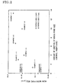
- Water permeation rate of the filter was assessed by the volume of water permeated per unit filtration area and unit time under a differential pressure of 1 kgf/cm 2 at a water temperature of 25°C. The results are shown in Table 1 and Figs. 2 and 3. TABLE 1 COMPOSITION OF FILM DEPOSITION SLURRY FILM DEPOSITION METHOD EVALUATION OF FILTER CHARACTERISTICS FRAMEWORK PARTICLE SIZE CONTROL AGENT CONTROL AGENT/FRAMEWORK RATIO POROUS MEMBRANE WATER PERMEATION RATE OF FILTER MEAN PORE SIZE MAX.
- a porous membrane with a micro-pore size of 0.090 ⁇ m is formed when framework particles with a particle size of 0.4 ⁇ m is used and the porous membrane is deposited from a slurry not supplemented with the micro-pore size control agent (Comparative Example 1-1).
- the micro-pore size control agent When the micro-pore size control agent is added, on the contrary, the micro-pore size could be expanded, and could be controlled by the weight ratio between the framework particles and the micro-pore size control agent (Examples 1-1, 1-3 and 1-5). Expanding the micro-pore size of the porous membrane permits the water permeation rate of the filter to be increased.
- micro-pore size of the porous membrane could be controlled by the weight ratio between the framework particles and the micro-pore size control agent in the dipping method as in the filtration deposition method, allowing the water permeation ratio of the filter to increase as the micro-pore size increases (Examples 1-2 and 1-4).
- the maximum micro-pore size of the porous membrane obtained by the filtration deposition method is smaller than that obtained by the dipping method, although the mean micro-pore size is identical, showing that the filtration deposition method could afford a sharp micro-pore size distribution as compared with the dipping method.
- the micro-pore size of the porous membrane could be controlled by the weight ratio between the framework particles and the micro-pore size control agent as in the case when the framework particles with the micro-pore size of 0.4 ⁇ m was used, also allowing the water permeation rate of the filter to be increased (Examples 1-6 to 1-8).
- the micro-pore size was controlled to be equal by changing the weight ratio between the framework particles and the micro-pore size control in Examples 1-9 and 1-10 agent even when the particle size of the framework particles is different.
- the water permeation rate was higher in Example 1-9 with a smaller particle size of the framework particles. This is conjectured because the air void ratio is larger despite the same micro-pore size.
- the manufacturing method according to the present invention can be also applied for the low temperature firing method in Japanese Unexamined Patent Application Publication No. 10-236887 disclosed by the inventors of the present invention.
- a binder such as a ceramic fine powder and ceramic sol particles comprising titania and zirconia, or a compound such as zirconium oxychloride and titanium tertachloride that is converted into a ceramic by heat treatment is added into the film deposition slurry, and the mixture is fired at a low temperature of 300 to 700°C where no neck is formed among the framework particles.
- Aron AS-7503 (trade name) was used as the acrylic resin for the micro-pore size control agent.
- Titania sol particles with a particle size of 30 nm were used as the binder. Titanium isopropozide was hydrolyzed to prepare an aqueous titania sol solution with titania concentration of 15% by weight and a pH value of about unity.
- the particle size of the sol particles was measured with a transmission type electron microscope.
- the mean value of the maximum diameter and the minimum diameter of the sol particles, or the mean value among 100 sol particles was defined to be the particle size of the sol.
- a slurry was prepared as follows. A mixed solution prepared by adding 0.1 to 1% by weight of an aqueous solution of an acrylic resin to 15% by weight of an aqueous solution of titania sol dropwise, and an alumina slurry prepared by suspending an alumina powder with a solid fraction concentration of 50% by weight in water and adjusted to pH 2 with 60% by weight of nitric acid, were independently prepared.
- the alumina slurry was added to the mixed solution above dropwise, and the film deposition slurries listed in Table 2 were prepared by mixing for 1 hour with a stirrer.
- the concentration of framework particles was 3% by weight in all the slurries.
- the slurry prepared as described above was deposited on the substrate C by the filtration deposition method, and a filter was obtained by firing at 600°C for 4 hours. Photographs of the cross section of the porous membrane were taken using a scanning type electron microscope so that the membrane length corresponding to 50 ⁇ m falls within one field of view, and the film thickness of the porous membrane was determined to be a mean value of the film thickness measured with respect to 100 fields of view.
- micro-pore size distribution was measured by the air-flow method described in ASTM F306, and the water permeation rate was assessed by the water permeation volume per unit filtration area per unit time with an inter-layer differential pressure of 1 kg/cm 2 at a temperature of 25°C. The results are shown in Table 2.
- the manufacturing method according to the present invention is quite useful in that a filter with a large water permeation rate (or a high treatment ability) can be manufactured even when the micro-pore size that determined the filtration ability is identical.
Landscapes
- Chemical & Material Sciences (AREA)
- Engineering & Computer Science (AREA)
- Ceramic Engineering (AREA)
- Chemical Kinetics & Catalysis (AREA)
- Inorganic Chemistry (AREA)
- Materials Engineering (AREA)
- Structural Engineering (AREA)
- Organic Chemistry (AREA)
- Manufacturing & Machinery (AREA)
- Separation Using Semi-Permeable Membranes (AREA)
- Filtering Materials (AREA)
- Porous Artificial Stone Or Porous Ceramic Products (AREA)
Claims (3)
- Procédé de fabrication d'un filtre comportant un substrat poreux et une membrane poreuse en céramique en tant que film de séparation sur une surface du substrat, comprenant l'étape consistant à disposer une suspension épaisse de dépôt de film contenant des particules d'ossature comprenant une céramique sur la surface du substrat,
dans lequel la suspension épaisse contient un matériau polymère organique comprenant de la gomme welan, de l'agar-agar ou un mélange de ceux-ci pour dilater les espaces parmi les particules d'ossature, et la taille de micropore de la membrane poreuse est régulée par le rapport en poids entre les particules d'ossature et le matériau polymère organique dans la suspension épaisse. - Procédé selon la revendication 1, dans lequel le matériau polymère organique comprend en outre un saccharide, du poly(alcool vinylique), une résine acrylique ou du poly(éthylène glycol).
- Procédé selon la revendication 1 ou 2, dans lequel les particules d'ossature ont une taille moyenne de particule de 1 à 10 µm.
Applications Claiming Priority (5)
| Application Number | Priority Date | Filing Date | Title |
|---|---|---|---|
| JP2446199 | 1999-02-01 | ||
| JP2446199 | 1999-02-01 | ||
| JP11086603A JP2000288325A (ja) | 1999-02-01 | 1999-03-29 | セラミック多孔質膜を分離膜とするフィルタの製造方法 |
| JP8660399 | 1999-03-29 | ||
| PCT/JP2000/000523 WO2000045945A1 (fr) | 1999-02-01 | 2000-01-31 | Procede de fabrication d'un filtre comportant un film poreux ceramique comme film de separation |
Publications (3)
| Publication Number | Publication Date |
|---|---|
| EP1070534A1 EP1070534A1 (fr) | 2001-01-24 |
| EP1070534A4 EP1070534A4 (fr) | 2005-04-20 |
| EP1070534B1 true EP1070534B1 (fr) | 2006-12-06 |
Family
ID=26361970
Family Applications (1)
| Application Number | Title | Priority Date | Filing Date |
|---|---|---|---|
| EP00902025A Expired - Lifetime EP1070534B1 (fr) | 1999-02-01 | 2000-01-31 | Procede de fabrication d'un filtre comportant un film poreux ceramique comme film de separation |
Country Status (5)
| Country | Link |
|---|---|
| US (1) | US6479099B1 (fr) |
| EP (1) | EP1070534B1 (fr) |
| JP (1) | JP2000288325A (fr) |
| DE (1) | DE60032198T2 (fr) |
| WO (1) | WO2000045945A1 (fr) |
Families Citing this family (14)
| Publication number | Priority date | Publication date | Assignee | Title |
|---|---|---|---|---|
| CA2440870A1 (fr) | 2001-03-14 | 2002-09-19 | Sekisui Chemical Co., Ltd. | Particules polymeres creuses, procede de production desdites particules, filtre ceramique poreux et procede de fabrication dudit filtre |
| US7149591B2 (en) | 2003-10-01 | 2006-12-12 | Cleveland State University | Multi-resolution controller |
| CA2604458C (fr) * | 2006-02-16 | 2010-09-21 | Ngk Insulators, Ltd. | Procede de fabrication d'une membrane poreuse en ceramique |
| CN101733045B (zh) * | 2008-11-14 | 2012-04-18 | 中国石油化工股份有限公司 | 一种浆态床反应器固液分离装置和方法 |
| CN101747228B (zh) * | 2008-11-28 | 2013-06-26 | 中国石油化工股份有限公司 | 一种酮或醛的氨肟化反应 |
| JP5632318B2 (ja) | 2011-03-24 | 2014-11-26 | 日本碍子株式会社 | ハニカムフィルタ及びその製造方法 |
| JP5599747B2 (ja) | 2011-03-24 | 2014-10-01 | 日本碍子株式会社 | ハニカム構造体及びその製造方法 |
| EP2832426B1 (fr) | 2012-03-30 | 2017-05-10 | NGK Insulators, Ltd. | Corps poreux en céramique en forme de nid d'abeilles, son procédé de fabrication, et structure de membrane de séparation en céramique en forme de nid d'abeilles |
| US20130323419A1 (en) * | 2012-06-05 | 2013-12-05 | Exxonmobil Research And Engineering Company | Methods for preparing polymer membranes on porous supports |
| DE102012017822B3 (de) | 2012-09-08 | 2013-09-19 | Technische Universität Bergakademie Freiberg | Verwendung eines Gemisches aus Konjakmehl und Welan Gum als Binder für die keramische und pulvermetallurgische Formgebung |
| JP2016175045A (ja) | 2015-03-20 | 2016-10-06 | 日本碍子株式会社 | 目封止ハニカム構造体 |
| JP6389134B2 (ja) | 2015-03-20 | 2018-09-12 | 日本碍子株式会社 | 目封止ハニカム構造体の製造方法、及び目封止ハニカム構造体 |
| JP6421139B2 (ja) * | 2016-03-31 | 2018-11-07 | 日本碍子株式会社 | モノリス型分離膜構造体 |
| JP7744715B1 (ja) * | 2024-05-27 | 2025-09-26 | イーセップ株式会社 | セラミック複合膜及び分離膜 |
Family Cites Families (11)
| Publication number | Priority date | Publication date | Assignee | Title |
|---|---|---|---|---|
| JPS61238315A (ja) * | 1985-04-12 | 1986-10-23 | Ngk Insulators Ltd | 複層フイルタの製造方法 |
| JPS6366566A (ja) | 1986-09-09 | 1988-03-25 | Seiko Epson Corp | 一成分トナ− |
| CA1269404A (fr) * | 1987-11-03 | 1990-05-22 | Mukesh K. Jain | Membrane poreuse d'oxydes de metal ou de silice frittable(s) |
| JPH0290927A (ja) * | 1988-09-29 | 1990-03-30 | Ngk Insulators Ltd | 無機多孔質膜の薄膜形成方法 |
| JPH02126924A (ja) * | 1988-11-07 | 1990-05-15 | Toto Ltd | セラミックス製非対称膜及びその製造方法 |
| JPH03284329A (ja) | 1990-03-30 | 1991-12-16 | Ngk Insulators Ltd | セラミック膜フイルタおよびその製造方法 |
| JP2799425B2 (ja) * | 1993-12-09 | 1998-09-17 | 工業技術院長 | セラミックス多孔質膜の製造方法 |
| US5656220A (en) * | 1995-08-11 | 1997-08-12 | Mountain Safety Research | Method for the extrusion of ceramic filter media |
| JP3284329B2 (ja) | 1995-08-30 | 2002-05-20 | 東京都 | 湿度センサ |
| US5948257A (en) * | 1996-05-03 | 1999-09-07 | Hexcel Corporation | Candle filter and method for making |
| JP3774037B2 (ja) * | 1996-12-27 | 2006-05-10 | 日本碍子株式会社 | チタニアを結合材とするセラミックス多孔質膜、これを用いたセラミックスフィルター及びこれらの製造方法 |
-
1999
- 1999-03-29 JP JP11086603A patent/JP2000288325A/ja active Pending
-
2000
- 2000-01-31 WO PCT/JP2000/000523 patent/WO2000045945A1/fr not_active Ceased
- 2000-01-31 DE DE60032198T patent/DE60032198T2/de not_active Expired - Lifetime
- 2000-01-31 US US09/647,125 patent/US6479099B1/en not_active Expired - Lifetime
- 2000-01-31 EP EP00902025A patent/EP1070534B1/fr not_active Expired - Lifetime
Also Published As
| Publication number | Publication date |
|---|---|
| EP1070534A4 (fr) | 2005-04-20 |
| US6479099B1 (en) | 2002-11-12 |
| JP2000288325A (ja) | 2000-10-17 |
| EP1070534A1 (fr) | 2001-01-24 |
| WO2000045945A1 (fr) | 2000-08-10 |
| DE60032198T2 (de) | 2007-09-20 |
| DE60032198D1 (de) | 2007-01-18 |
Similar Documents
| Publication | Publication Date | Title |
|---|---|---|
| EP1070533B1 (fr) | Procede de fabrication d'un filtre comportant un film ceramique poreux comme film de separation | |
| EP1070534B1 (fr) | Procede de fabrication d'un filtre comportant un film poreux ceramique comme film de separation | |
| CA1103105A (fr) | Methode de fabrication d'elements porteurs pour filtres poreux | |
| US20040258611A1 (en) | Colloidal composite sol gel formulation with an expanded gel network for making thick inorganic coatings | |
| EP3212313A1 (fr) | Filtre à membrane inorganique et procédés associés | |
| KR20020063554A (ko) | 화학적으로 결합된 졸-겔 세라믹의 형성방법 | |
| CN112939580B (zh) | 一种陶瓷过滤膜的制备方法 | |
| CN108201794B (zh) | 利用经氧化处理的碳化硅的水处理用陶瓷分离膜及其制备方法 | |
| US20030166449A1 (en) | Homogeneous bulky porous ceramic material | |
| CA2312247C (fr) | Membrane en ceramique | |
| Nakahira et al. | Green fabrication of porous ceramics using an aqueous electrophoretic deposition process | |
| US6341701B1 (en) | Ceramic porous membrane including ceramic of ceramic and ceramic sol particles, ceramic porous body including the membrane, and method of manufacturing the membrane | |
| JP2001240480A (ja) | 多孔質セラミック構造体およびその製造方法並びに流体透過部材 | |
| CN1487850A (zh) | 分层结构型过滤器及其制备方法 | |
| EP0922478A2 (fr) | Filtre poreux céramique et procédé pour sa fabrication | |
| RU2040371C1 (ru) | Способ изготовления фильтрующего материала | |
| DE4116522C2 (de) | Verfahren zur Herstellung von mit einer porösen alpha-Al¶2¶O¶3¶-Schicht versehenen Substraten, nach dem Verfahren erhaltene Substrate sowie Beschichtungsmittel zur Durchführung des Verfahrens | |
| KR101993448B1 (ko) | 수처리용 다공성 세라믹 분리막 및 이의 제조방법 | |
| CN118324534A (zh) | 一种陶瓷复合材料3d打印线材的制备方法 | |
| JP4024704B2 (ja) | 複層構造セラミックスフィルターの製造方法 | |
| JP2001261465A (ja) | セラミックス多孔質フィルターの製造方法 | |
| JP3057313B2 (ja) | セラミックス多孔質膜及びその製造法 | |
| JPH11292653A (ja) | セラミック多孔体及びその製造方法 | |
| RU2205061C1 (ru) | Способ изготовления фильтрующих элементов с керамическим активным слоем на пористой углеродной подложке | |
| JPH0717780A (ja) | 多孔質セラミックス膜の製造方法 |
Legal Events
| Date | Code | Title | Description |
|---|---|---|---|
| PUAI | Public reference made under article 153(3) epc to a published international application that has entered the european phase |
Free format text: ORIGINAL CODE: 0009012 |
|
| 17P | Request for examination filed |
Effective date: 20001005 |
|
| AK | Designated contracting states |
Kind code of ref document: A1 Designated state(s): AT BE CH CY DE DK ES FI FR GB GR IE IT LI LU MC NL PT SE |
|
| RBV | Designated contracting states (corrected) |
Designated state(s): BE DE FR GB NL |
|
| A4 | Supplementary search report drawn up and despatched |
Effective date: 20050304 |
|
| RIC1 | Information provided on ipc code assigned before grant |
Ipc: 7C 04B 41/85 B Ipc: 7C 04B 41/45 B Ipc: 7B 01D 67/00 B Ipc: 7B 01D 69/10 B Ipc: 7B 01D 71/02 A |
|
| GRAP | Despatch of communication of intention to grant a patent |
Free format text: ORIGINAL CODE: EPIDOSNIGR1 |
|
| GRAS | Grant fee paid |
Free format text: ORIGINAL CODE: EPIDOSNIGR3 |
|
| GRAA | (expected) grant |
Free format text: ORIGINAL CODE: 0009210 |
|
| AK | Designated contracting states |
Kind code of ref document: B1 Designated state(s): BE DE FR GB NL |
|
| REG | Reference to a national code |
Ref country code: GB Ref legal event code: FG4D |
|
| REF | Corresponds to: |
Ref document number: 60032198 Country of ref document: DE Date of ref document: 20070118 Kind code of ref document: P |
|
| ET | Fr: translation filed | ||
| PLBE | No opposition filed within time limit |
Free format text: ORIGINAL CODE: 0009261 |
|
| STAA | Information on the status of an ep patent application or granted ep patent |
Free format text: STATUS: NO OPPOSITION FILED WITHIN TIME LIMIT |
|
| 26N | No opposition filed |
Effective date: 20070907 |
|
| REG | Reference to a national code |
Ref country code: FR Ref legal event code: PLFP Year of fee payment: 17 |
|
| REG | Reference to a national code |
Ref country code: FR Ref legal event code: PLFP Year of fee payment: 18 |
|
| REG | Reference to a national code |
Ref country code: FR Ref legal event code: PLFP Year of fee payment: 19 |
|
| PGFP | Annual fee paid to national office [announced via postgrant information from national office to epo] |
Ref country code: NL Payment date: 20181213 Year of fee payment: 20 |
|
| PGFP | Annual fee paid to national office [announced via postgrant information from national office to epo] |
Ref country code: FR Payment date: 20181213 Year of fee payment: 20 Ref country code: BE Payment date: 20181217 Year of fee payment: 20 |
|
| PGFP | Annual fee paid to national office [announced via postgrant information from national office to epo] |
Ref country code: GB Payment date: 20190130 Year of fee payment: 20 Ref country code: DE Payment date: 20190115 Year of fee payment: 20 |
|
| REG | Reference to a national code |
Ref country code: DE Ref legal event code: R071 Ref document number: 60032198 Country of ref document: DE |
|
| REG | Reference to a national code |
Ref country code: NL Ref legal event code: MK Effective date: 20200130 |
|
| REG | Reference to a national code |
Ref country code: GB Ref legal event code: PE20 Expiry date: 20200130 |
|
| REG | Reference to a national code |
Ref country code: BE Ref legal event code: MK Effective date: 20200131 |
|
| PG25 | Lapsed in a contracting state [announced via postgrant information from national office to epo] |
Ref country code: GB Free format text: LAPSE BECAUSE OF EXPIRATION OF PROTECTION Effective date: 20200130 |