EP1070923A2 - Vorrichtung zur Befestigung von Solarmodulen - Google Patents
Vorrichtung zur Befestigung von Solarmodulen Download PDFInfo
- Publication number
- EP1070923A2 EP1070923A2 EP00250239A EP00250239A EP1070923A2 EP 1070923 A2 EP1070923 A2 EP 1070923A2 EP 00250239 A EP00250239 A EP 00250239A EP 00250239 A EP00250239 A EP 00250239A EP 1070923 A2 EP1070923 A2 EP 1070923A2
- Authority
- EP
- European Patent Office
- Prior art keywords
- profile
- frame
- clamping piece
- positive
- support profile
- Prior art date
- Legal status (The legal status is an assumption and is not a legal conclusion. Google has not performed a legal analysis and makes no representation as to the accuracy of the status listed.)
- Granted
Links
Images

Classifications
-
- F—MECHANICAL ENGINEERING; LIGHTING; HEATING; WEAPONS; BLASTING
- F24—HEATING; RANGES; VENTILATING
- F24S—SOLAR HEAT COLLECTORS; SOLAR HEAT SYSTEMS
- F24S25/00—Arrangement of stationary mountings or supports for solar heat collector modules
- F24S25/60—Fixation means, e.g. fasteners, specially adapted for supporting solar heat collector modules
- F24S25/63—Fixation means, e.g. fasteners, specially adapted for supporting solar heat collector modules for fixing modules or their peripheral frames to supporting elements
- F24S25/634—Clamps; Clips
-
- F—MECHANICAL ENGINEERING; LIGHTING; HEATING; WEAPONS; BLASTING
- F24—HEATING; RANGES; VENTILATING
- F24S—SOLAR HEAT COLLECTORS; SOLAR HEAT SYSTEMS
- F24S25/00—Arrangement of stationary mountings or supports for solar heat collector modules
- F24S25/20—Peripheral frames for modules
-
- F—MECHANICAL ENGINEERING; LIGHTING; HEATING; WEAPONS; BLASTING
- F24—HEATING; RANGES; VENTILATING
- F24S—SOLAR HEAT COLLECTORS; SOLAR HEAT SYSTEMS
- F24S25/00—Arrangement of stationary mountings or supports for solar heat collector modules
- F24S25/30—Arrangement of stationary mountings or supports for solar heat collector modules using elongate rigid mounting elements extending substantially along the supporting surface, e.g. for covering buildings with solar heat collectors
- F24S25/33—Arrangement of stationary mountings or supports for solar heat collector modules using elongate rigid mounting elements extending substantially along the supporting surface, e.g. for covering buildings with solar heat collectors forming substantially planar assemblies, e.g. of coplanar or stacked profiles
-
- F—MECHANICAL ENGINEERING; LIGHTING; HEATING; WEAPONS; BLASTING
- F24—HEATING; RANGES; VENTILATING
- F24S—SOLAR HEAT COLLECTORS; SOLAR HEAT SYSTEMS
- F24S25/00—Arrangement of stationary mountings or supports for solar heat collector modules
- F24S25/60—Fixation means, e.g. fasteners, specially adapted for supporting solar heat collector modules
- F24S25/63—Fixation means, e.g. fasteners, specially adapted for supporting solar heat collector modules for fixing modules or their peripheral frames to supporting elements
- F24S25/632—Side connectors; Base connectors
-
- F—MECHANICAL ENGINEERING; LIGHTING; HEATING; WEAPONS; BLASTING
- F24—HEATING; RANGES; VENTILATING
- F24S—SOLAR HEAT COLLECTORS; SOLAR HEAT SYSTEMS
- F24S25/00—Arrangement of stationary mountings or supports for solar heat collector modules
- F24S25/60—Fixation means, e.g. fasteners, specially adapted for supporting solar heat collector modules
- F24S25/65—Fixation means, e.g. fasteners, specially adapted for supporting solar heat collector modules for coupling adjacent supporting elements, e.g. for connecting profiles together
-
- F—MECHANICAL ENGINEERING; LIGHTING; HEATING; WEAPONS; BLASTING
- F24—HEATING; RANGES; VENTILATING
- F24S—SOLAR HEAT COLLECTORS; SOLAR HEAT SYSTEMS
- F24S25/00—Arrangement of stationary mountings or supports for solar heat collector modules
- F24S25/60—Fixation means, e.g. fasteners, specially adapted for supporting solar heat collector modules
- F24S2025/6002—Fixation means, e.g. fasteners, specially adapted for supporting solar heat collector modules by using hooks
-
- F—MECHANICAL ENGINEERING; LIGHTING; HEATING; WEAPONS; BLASTING
- F24—HEATING; RANGES; VENTILATING
- F24S—SOLAR HEAT COLLECTORS; SOLAR HEAT SYSTEMS
- F24S25/00—Arrangement of stationary mountings or supports for solar heat collector modules
- F24S25/60—Fixation means, e.g. fasteners, specially adapted for supporting solar heat collector modules
- F24S2025/6004—Fixation means, e.g. fasteners, specially adapted for supporting solar heat collector modules by clipping, e.g. by using snap connectors
-
- F—MECHANICAL ENGINEERING; LIGHTING; HEATING; WEAPONS; BLASTING
- F24—HEATING; RANGES; VENTILATING
- F24S—SOLAR HEAT COLLECTORS; SOLAR HEAT SYSTEMS
- F24S25/00—Arrangement of stationary mountings or supports for solar heat collector modules
- F24S25/60—Fixation means, e.g. fasteners, specially adapted for supporting solar heat collector modules
- F24S2025/6007—Fixation means, e.g. fasteners, specially adapted for supporting solar heat collector modules by using form-fitting connection means, e.g. tongue and groove
-
- F—MECHANICAL ENGINEERING; LIGHTING; HEATING; WEAPONS; BLASTING
- F24—HEATING; RANGES; VENTILATING
- F24S—SOLAR HEAT COLLECTORS; SOLAR HEAT SYSTEMS
- F24S25/00—Arrangement of stationary mountings or supports for solar heat collector modules
- F24S2025/80—Special profiles
- F24S2025/804—U-, C- or O-shaped; Hat profiles
-
- Y—GENERAL TAGGING OF NEW TECHNOLOGICAL DEVELOPMENTS; GENERAL TAGGING OF CROSS-SECTIONAL TECHNOLOGIES SPANNING OVER SEVERAL SECTIONS OF THE IPC; TECHNICAL SUBJECTS COVERED BY FORMER USPC CROSS-REFERENCE ART COLLECTIONS [XRACs] AND DIGESTS
- Y02—TECHNOLOGIES OR APPLICATIONS FOR MITIGATION OR ADAPTATION AGAINST CLIMATE CHANGE
- Y02B—CLIMATE CHANGE MITIGATION TECHNOLOGIES RELATED TO BUILDINGS, e.g. HOUSING, HOUSE APPLIANCES OR RELATED END-USER APPLICATIONS
- Y02B10/00—Integration of renewable energy sources in buildings
- Y02B10/20—Solar thermal
-
- Y—GENERAL TAGGING OF NEW TECHNOLOGICAL DEVELOPMENTS; GENERAL TAGGING OF CROSS-SECTIONAL TECHNOLOGIES SPANNING OVER SEVERAL SECTIONS OF THE IPC; TECHNICAL SUBJECTS COVERED BY FORMER USPC CROSS-REFERENCE ART COLLECTIONS [XRACs] AND DIGESTS
- Y02—TECHNOLOGIES OR APPLICATIONS FOR MITIGATION OR ADAPTATION AGAINST CLIMATE CHANGE
- Y02E—REDUCTION OF GREENHOUSE GAS [GHG] EMISSIONS, RELATED TO ENERGY GENERATION, TRANSMISSION OR DISTRIBUTION
- Y02E10/00—Energy generation through renewable energy sources
- Y02E10/40—Solar thermal energy, e.g. solar towers
- Y02E10/47—Mountings or tracking
Definitions
- the invention relates to a fastening of solar modules that have a profile frame.
- the object of the invention is to achieve attachment of the solar modules to support profiles, which is easy to install and inexpensive. This task is solved with the characterizing features of claim 1, advantageous embodiments are the subject of subclaims.
- the device according to the invention for fastening solar modules which has a profile frame own and in between the frame of the solar module and a support profile there is a non-positive connection, that between the support profile and the frame of the solar module by means of a clamping piece a positive and non-positive Connection is established.
- a clamping piece or several clamping pieces per side of the frame of the Solar module are used.
- the clamping piece in the sense of the invention can also have a longer length, so that it could be described as a clamping rail.
- connection between the support profile and the clamping piece is inventively formed as a non-positive and / or a positive connection.
- the clamping piece (s) are installed preferably in advance of assembling the solar module. So there are prefabricated support profiles Delivered to the construction site with welded or screwed clamps.
- the positive connection is preferably used when the support profiles already are installed or they are attached to the support profiles before installation.
- connection between the frame of the solar module and the clamping piece is always a positive and non-positive connection.
- the best known frames of solar modules have C profiles as connection options on, with their opening either perpendicular to the solar module level or in a point parallel to the solar module level.
- the legs of the C - Profile cranked.
- a support profile is used in an embodiment of the invention which has a C-profile with its opening pointing towards the frame of the solar module with legs bent inwards and the C-profiles are connected with a clamping piece which connects at least one leg of the C-profile of the frame with one leg of the C-profile of the support profile in a non-positive and positive manner.
- a support profile is also used in an embodiment of the invention which has a C-profile with its opening in the direction of the frame with inwards is cranked legs, wherein the C - profiles are connected to a clamping piece that connects at least one leg of the C - profile of the frame with one leg of the C - profile of the support profile in a non-positive and positive manner.
- connection between the clamping piece and the C-profile of the frame here consists of a locking lug arranged on the clamping piece, which acts non-positively and positively on the inside of the leg, and of a stop arranged on the clamping piece for the C-profile of the frame, the one prevents lateral displacement of the C-profile of the frame relative to the clamping piece in the plane of the cross-section of the C-profile of the frame.
- connection between the clamping piece and the support profile exists in both cases from an angled part arranged on the clamping piece, the form-fitting behind a crank of a leg of the support profile engages and one arranged on the clamping piece Stop for the support profile opposite to a lateral displacement of the support profile the clamping piece in the plane of the cross section of the support profile prevented.
- both for the support profile as well as the frame of the solar module there are two stops, one lateral movement of the support profile or the C - profile of the frame compared to the Prevent the clamping piece in the plane of the cross-section of the profiles.
- the latch is like this relieved of forces that could break the locking connection.
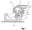
- the clamping piece arrangement shown in FIG. 1 is used in particular when assembling a plurality of solar modules.
- Part of the frame 2 of the solar module 1 is a C-profile with its opening pointing in the direction of the support profile 4 with legs bent inwards.
- the support profile 4 is a C-profile with its opening in the direction of the frame 2 of the solar module 1 with legs bent inwards.
- the C - profiles are connected with a clamping piece 3 in a non-positive and positive manner.
- the clamping piece 3 has a locking lug 5, which engages non-positively and positively behind a crank 6 of the leg of the C-profile of the frame 2.
- a stop 7 arranged on the clamping piece 3 for the C profile of the frame 2 of the solar module 1 prevents the C profile of the frame 2 from shifting laterally relative to the clamping piece 3 in the plane of the cross section of the C profile of the frame 2.
- connection between the clamping piece 3 and the support profile 4 consists of a arranged on the clamping piece 3 angled part 8, the form-fitting behind a Crank of a leg 9 of the support profile 4 engages and one arranged on the clamping piece 3 Stop 13 for the support profile 4, the lateral displacement of the support profile 4 compared to the clamping piece 3 in the plane of the cross section of the support profile 4 prevented.
- the support profile 4 and the clamping piece 2 are coordinated so that the outer edge of the frame 2, the center of the support profile 4 after assembly is not exceeds. So the support profile 4 for a further, to be arranged solar modules be used.
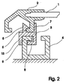
- Fig. 2 shows a clamping piece arrangement also with only one stop 7 for the frame 2 of the solar module 1, as is preferably used at the end of the arrangement of several solar modules 1.
- the frame 2 of the solar module 1 completely covers the support profile 4 here.
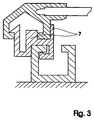
- FIG. 3 shows a clamping piece 3 with two stops 7 for the frame 2 of the solar module 1, which prevent lateral displacement of the C-profile of the frame 2 relative to the clamping piece 3 in the plane of the cross section of the profile.
- the locking lug 5 is thus relieved of laterally acting forces that could break the locking connection.
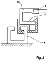
- FIG. 4 shows a clamping piece arrangement when assembling several solar modules 1, the frame 10 of the solar module 1 being a C-profile, which has the side face of a leg 11 in the direction of the supporting profile 4.
- the connection between the clamping piece 3 and the C-profile of the frame 10 here consists of a locking lug 5 arranged on the clamping piece 3, which acts non-positively and positively on the inside of the leg 11, and of a stop 7 arranged on the clamping piece 3 for the C - Profile of the frame 10, which prevents lateral displacement of the C-profile of the frame 10 relative to the clamping piece 3 in the plane of the cross-section of the C-profile of the frame 10.
Landscapes
- Engineering & Computer Science (AREA)
- Chemical & Material Sciences (AREA)
- Life Sciences & Earth Sciences (AREA)
- Sustainable Development (AREA)
- Sustainable Energy (AREA)
- Thermal Sciences (AREA)
- Physics & Mathematics (AREA)
- Combustion & Propulsion (AREA)
- Mechanical Engineering (AREA)
- General Engineering & Computer Science (AREA)
- Photovoltaic Devices (AREA)
- Roof Covering Using Slabs Or Stiff Sheets (AREA)
- Connection Of Plates (AREA)
Abstract
Das Klemmstück (3) weist eine Rastnase (5) auf, die kraft- und formschlüssig hinter eine Kröpfung (6) des Schenkels des C - Profils des Rahmens (2) greift.
Ein am Klemmstück (3) angeordneter Anschlag (7) verhindert ein seitliches Verschieben des C - Profils des Rahmens (2).
Die Verbindung zwischen dem Klemmstück (3) und dem Tragprofil (4) besteht aus einem am Klemmstück (3) angeordneten abgewinkelten Teil (8), das formschlüssig hinter eine Kröpfung eines Schenkels (9) des Tragprofils (4) greift und einem am Klemmstück (3) angeordneten Anschlag (13)
Description
Dies geschieht in einer bevorzugten Ausführung mittels einer am Klemmstück angeordneten Rastnase, die kraft- und formschlüssig hinter eine Kröpfung des Schenkels des C - Profils des Rahmens greift und einem am Klemmstück angeordneten Anschlag für das C - Profil des Rahmens, der ein seitliches Verschieben des C - Profils des Rahmens gegenüber dem Klemmstück in der Ebene des Querschnitts des C - Profils des Rahmens verhindert.
Die Verbindung zwischen dem Klemmstück und dem C - Profil des Rahmens besteht hier aus einer am Klemmstück angeordneten Rastnase, die kraft- und formschlüssig auf die Innenseite des Schenkels einwirkt, und aus einem am Klemmstück angeordneten Anschlag für das C - Profil des Rahmens, der ein seitliches Verschieben des C - Profils des Rahmens gegenüber dem Klemmstück in der Ebene des Querschnitts des C - Profils des Rahmens verhindert.
- Fig. 1
- Klemmstückanordnung bei Montage mehrerer Solarmodule,
- Fig. 2
- Klemmstück mit einem Anschlag für den Rahmen des Solarmoduls,
- Fig. 3
- Klemmstück mit zwei Anschlägen für den Rahmen des Solarmoduls,
- Fig. 4
- Klemmstückanordnung bei Montage mehrerer Solarmodule und
- Fig. 5
- Klemmstück mit besonders ausgebildeter Rastnase.
Die Verbindung zwischen dem Klemmstück 3 und dem C - Profil des Rahmens 10 besteht hier aus einer am Klemmstück 3 angeordneten Rastnase 5, die kraft- und formschlüssig auf die Innenseite des Schenkels 11 einwirkt, und aus einem am Klemmstück 3 angeordneten Anschlag 7 für das C - Profil des Rahmens 10, der ein seitliches Verschieben des C - Profils des Rahmens 10 gegenüber dem Klemmstück 3 in der Ebene des Querschnitts des C - Profils des Rahmens 10 verhindert.
- 1
- Solarmodul
- 2
- Rahmen des Solarmoduls
- 3
- Klemmstück
- 4
- Tragprofil
- 5
- Rastnase
- 6
- Kröpfung
- 7
- Anschlag
- 8
- abgewinkeltes Teil
- 9
- Kröpfung
- 10
- Rahmen des Solarmoduls
- 11
- Schenkel
- 12
- Kehlung mit Kunststoffkörper
- 13
- Anschlag
Claims (12)
- Vorrichtung zur Befestigung von Solarmodulen, die einen Profilrahmen besitzen und bei der zwischen dem Rahmen des Solarmoduls und einem Tragprofil eine kraftschlüssige Verbindung besteht, dadurch gekennzeichnet, daßzwischen dem Tragprofil (4) und dem Rahmen (2, 10) des Solarmoduls (1) mittels eines Klemmstückes (3) eine form- und kraftschlüssige Verbindung hergestellt ist.
- Vorrichtung nach Anspruch 1, dadurch gekennzeichnet, daßmehrere Klemmstücke (3) jeweils eine Seite des Rahmens (2, 10) des Solarmoduls (1) mit dem Tragprofil (4) verbinden.
- Vorrichtung nach Anspruch 1, dadurch gekennzeichnet, daßdie Verbindung zwischen dem Tragprofil (4) und dem Klemmstück (3) eine kraftschlüssige und/oder eine formschlüssige ist.
- Vorrichtung nach Anspruch 1, dadurch gekennzeichnet, daßdie Verbindung zwischen den Rahmen (2, 10) des Solarmoduls (1) und dem Klemmstück (3) eine form- und kraftschlüssige ist.
- Vorrichtung nach Anspruch 1, dadurch gekennzeichnet, daßBestandteil des Rahmens (2) des Solarmoduls (1) ein mit seiner Öffnung in Richtung des Tragprofils (4) weisendes C - Profil mit nach innen gekröpften Schenkeln ist, das Tragprofil (4) ein mit seiner Öffnung in Richtung auf den Rahmen (2) weisendes C - Profil mit nach innen gekröpften Schenkeln ist und die C - Profile mit einem Klemmstück (3) verbunden sind, das mindestens einen Schenkel des C - Profils des Rahmens (2) mit einem Schenkel des C - Profils des Tragprofils (4) kraft- und formschlüssig verbindet.
- Vorrichtung nach Anspruch 5, dadurch gekennzeichnet, daßdie Verbindung zwischen dem Klemmstück (3) und dem C - Profil des Rahmens (2) aus einer am Klemmstück (3) angeordneten Rastnase (5), die kraft- und formschlüssig hinter eine Kröpfung (6) des Schenkels des C - Profils des Rahmens (2) greift, besteht und aus einem Anschlag (7) für das C - Profil des Rahmens (2), der ein seitliches Verschieben des C - Profils des Rahmens (2) gegenüber dem Klemmstück (3) in der Ebene des Querschnitts des C - Profils des Rahmens (2) verhindert.
- Vorrichtung nach Anspruch 1, dadurch gekennzeichnet, daßBestandteil des Rahmens (10) des Solarmoduls (1) ein C - Profil ist, das mit der Seitenfläche eines Schenkels (11) in Richtung Tragprofil (4) weist, das Tragprofil (4) ein mit seiner Öffnung in Richtung auf den Rahmen (10) weisendes C - Profil mit nach innen gekröpften Schenkeln ist und die C - Profile mit einem Klemmstück (3) verbunden sind, das mindestens einen Schenkel des C - Profils des Rahmens (10) mit einem Schenkel des C - Profils des Tragprofils (4) kraft- und formschlüssig verbindet.
- Vorrichtung nach Anspruch 7, dadurch gekennzeichnet, daßdie Verbindung zwischen dem Klemmstück (3) und dem C - Profil des Rahmens (10) aus einer am Klemmstück (3) angeordneten Rastnase (5), die kraft- und formschlüssig auf die Innenseite des Schenkels (11) einwirkt, besteht und aus einem Anschlag (7) für das C - Profil des Rahmens (10), der ein seitliches Verschieben des C - Profils des Rahmens (10) gegenüber dem Klemmstück (3) in der Ebene des Querschnitts des C - Profils des Rahmens (10) verhindert.
- Vorrichtung nach Anspruch 5 oder 7, dadurch gekennzeichnet, daßdie Verbindung zwischen dem Klemmstück (3) und dem Tragprofil (4) aus einem am Klemmstück (3) angeordneten abgewinkelten Teil (8) besteht, das formschlüssig hinter eine Kröpfung eines Schenkels (9) des Tragprofils (4) greift und ein Anschlag (13) für das Tragprofil (4) vorhanden ist, der ein seitliches Verschieben des Tragprofils (4) gegenüber dem Klemmstück (3) in der Ebene des Querschnitts des Tragprofils (4) verhindert.
- Vorrichtung nach Anspruch 6, 8 oder 9, dadurch gekennzeichnet, daßzwei Anschläge (7) und/ oder (13) vorhanden sind, die ein seitliches Verschieben des Tragprofils (4) bzw. des C - Profils der Rahmen (2, 10) gegenüber dem Klemmstück (3) in der Ebene des Querschnitts der Profile verhindern.
- Vorrichtung nach Anspruch 5 oder 7, dadurch gekennzeichnet, daßdas Tragprofil (4) und das Klemmstück (2) so aufeinander abgestimmt sind, daß die äußere Kante der Rahmen (2, 10) die Mitte des Tragprofils (4) nach erfolgter Montage nicht überschreitet.
- Vorrichtung nach Anspruch 6 oder 8, dadurch gekennzeichnet, daßdie Kehlung (12) der Rastnase (5) eine schräge Flache aufweist oder in der Kehlung (12) ein elastischer Kunststoffkörper angeordnet ist, wobei die Fläche und der Körper so bemessen sind, daß die Rastfunktion der Rastnase (5) erhalten bleibt.
Applications Claiming Priority (2)
| Application Number | Priority Date | Filing Date | Title |
|---|---|---|---|
| DE19934073A DE19934073B4 (de) | 1999-07-19 | 1999-07-19 | Vorrichtung zur Befestigung von Solarmodulen |
| DE19934073 | 1999-07-19 |
Publications (3)
| Publication Number | Publication Date |
|---|---|
| EP1070923A2 true EP1070923A2 (de) | 2001-01-24 |
| EP1070923A3 EP1070923A3 (de) | 2002-07-17 |
| EP1070923B1 EP1070923B1 (de) | 2004-01-07 |
Family
ID=7915463
Family Applications (1)
| Application Number | Title | Priority Date | Filing Date |
|---|---|---|---|
| EP00250239A Expired - Lifetime EP1070923B1 (de) | 1999-07-19 | 2000-07-14 | Vorrichtung zur Befestigung von Solarmodulen |
Country Status (8)
| Country | Link |
|---|---|
| US (1) | US6370828B1 (de) |
| EP (1) | EP1070923B1 (de) |
| JP (1) | JP2001090275A (de) |
| AT (1) | ATE257574T1 (de) |
| AU (1) | AU4870200A (de) |
| DE (2) | DE19934073B4 (de) |
| DK (1) | DK1070923T3 (de) |
| ES (1) | ES2213541T3 (de) |
Cited By (18)
| Publication number | Priority date | Publication date | Assignee | Title |
|---|---|---|---|---|
| NL1020620C2 (nl) * | 2002-05-17 | 2003-11-21 | Alcoa Nederland Bv | Draagsysteem voor zonnepanelen. |
| EP1947402A1 (de) * | 2007-01-18 | 2008-07-23 | Aplisun Develop, S.L. | Stützrahmen für Sonnenpaneelen |
| EP2182303A2 (de) * | 2008-10-22 | 2010-05-05 | Michelberger Energietechnik GmbH | Montagesystem |
| DE102008055937A1 (de) * | 2008-11-05 | 2010-05-12 | Schmidt, Christoph, Dr.-Ing. | Einleg-Klemm System |
| WO2008157201A3 (en) * | 2007-06-19 | 2010-07-01 | Bp Corporation North America Inc. | Solar module with a frame for mounting a solar panel |
| FR2945609A1 (fr) * | 2009-05-12 | 2010-11-19 | Avancis Gmbh & Co Kg | Dispositif de fixation et procede de montage de modules solaires. |
| FR2951508A1 (fr) * | 2009-10-21 | 2011-04-22 | Marcel Gillot | Dispositif de pose d'un element plat et profile de base pour un tel dispositif |
| DE202012003649U1 (de) | 2012-01-24 | 2012-04-27 | Altec Solartechnik Ag | Vorrichtung zur Befestigung von Flächenkörpern mit Rahmen, insbesondere Photovoltaik- oder thermischen Solarmodulen |
| WO2012014203A3 (en) * | 2010-07-26 | 2012-07-19 | Efraim Molek | Locking mechanism for panels |
| CH705036A1 (de) * | 2011-05-27 | 2012-11-30 | Markus Gisler | Verkleidungssystem zur Verkleidung einer Gebäudeaussenfläche. |
| EP1647782A3 (de) * | 2004-10-13 | 2013-05-22 | Robert Bosch Gmbh | Befestigungsvorrichtung für mindestens einen Sonnenkollektor |
| WO2013120677A1 (de) * | 2012-02-13 | 2013-08-22 | Ilzhoefer Werner | Halter für ein solarmodul |
| FR2989154A1 (fr) * | 2012-04-10 | 2013-10-11 | Ciel Et Terre | Procede de fixation de panneau photovoltaique. |
| ITTV20120238A1 (it) * | 2012-12-18 | 2014-06-19 | Roberto Corvaglia | Sistema per il fissaggio di moduli per la produzione di energia da fonte solare |
| EP2362160A3 (de) * | 2010-02-25 | 2014-09-17 | Zimmermann Stalltechnik GmbH | Ständer-Vorrichtung für Photovoltaik-Module |
| EP2747151A3 (de) * | 2012-12-24 | 2015-01-21 | Samsung SDI Co., Ltd. | Vorrichtung zur photovoltaischen Energieerzeugung |
| EP2426432A3 (de) * | 2010-09-01 | 2015-03-18 | Mounting Systems GmbH | Profilschiene, Halteelement und damit gebildete Solarmodulanordnung, insbesondere für eine Quermontage von Solarmodulen |
| WO2024197326A1 (en) * | 2023-03-28 | 2024-10-03 | World4Solar Inc. | Mounting system for solar modules |
Families Citing this family (133)
| Publication number | Priority date | Publication date | Assignee | Title |
|---|---|---|---|---|
| AU6763600A (en) * | 1999-08-11 | 2001-03-05 | Solar Strategies Development, Inc | Mounting apparatus and photovoltaic mounting system for a solar panel and methodof mounting a solar panel |
| GB2388399B (en) * | 2001-01-19 | 2004-10-06 | Vkr Holding As | A roof window assembly and components |
| US6804918B2 (en) * | 2001-01-19 | 2004-10-19 | Vkr Holding A/S | Roof window assembly comprising a window component and an external screening accessory |
| DE20110459U1 (de) | 2001-06-25 | 2001-09-20 | Osmer Klaus Dieter | Montagesystem für gerahmte Solarmodule |
| US7434362B2 (en) | 2001-07-20 | 2008-10-14 | Unirac, Inc. | System for removably and adjustably mounting a device on a surface |
| US6606823B1 (en) * | 2002-03-20 | 2003-08-19 | Ford Motor Land Development Corporation | Modular roof covering system |
| WO2003087493A1 (en) * | 2002-04-11 | 2003-10-23 | Rwe Schott Solar Inc. | Apparatus and method for mounting photovoltaic power generating systems on buildings |
| US7574842B2 (en) * | 2002-04-11 | 2009-08-18 | Schott Solar, Inc. | Apparatus for mounting photovoltaic power generating systems on buildings |
| DE10216625B4 (de) * | 2002-04-15 | 2006-02-09 | U.F.E. Solar-Vertriebsgesellschaft Mbh | Befestigungsvorrichtung für eine abdichtende Halterung eines Flächenkörpers |
| DE10224437A1 (de) * | 2002-06-01 | 2003-12-11 | Hans Joachim Damm | Befestigungsvorrichtung für ein Solarkollektor-Modul |
| DE20209892U1 (de) | 2002-06-26 | 2002-10-02 | Mäder, Wolfgang, 99869 Grabsleben | Anordnung zur Befestigung von Solarmodulen an Wänden und auf Dächern von Gebäuden |
| US6968654B2 (en) * | 2003-01-08 | 2005-11-29 | Mcconnell Energy Solutions, Llc | Solar panel mounting structure, solar panel system, and methods of making and installing thereof |
| US7600349B2 (en) * | 2003-02-26 | 2009-10-13 | Unirac, Inc. | Low profile mounting system |
| US7592537B1 (en) | 2004-02-05 | 2009-09-22 | John Raymond West | Method and apparatus for mounting photovoltaic modules |
| US7856769B2 (en) * | 2004-02-13 | 2010-12-28 | Pvt Solar, Inc. | Rack assembly for mounting solar modules |
| US7297866B2 (en) * | 2004-03-15 | 2007-11-20 | Sunpower Corporation | Ventilated photovoltaic module frame |
| US7406800B2 (en) | 2004-05-18 | 2008-08-05 | Andalay Solar, Inc. | Mounting system for a solar panel |
| US8141306B2 (en) * | 2004-10-22 | 2012-03-27 | Kyocera Corporation | Solar battery module device and method of installing the same |
| ES2293602T3 (es) * | 2005-01-10 | 2008-03-16 | Conergy Ag | Sistema de montaje con corredera roscada. |
| NL1028379C2 (nl) * | 2005-02-23 | 2006-08-24 | Girasol Internat B V | Inrichting en werkwijze voor het bevestigen van objecten, in het bijzonder zonnepanelen, op een dak. |
| PL1896785T3 (pl) * | 2005-06-24 | 2014-04-30 | Vkr Holding As | Kolektor słoneczny |
| US20120085042A1 (en) * | 2005-11-14 | 2012-04-12 | Macdonald Robert B | Wall Panel Systems for Rigid Wall Panels |
| DE102006061284A1 (de) * | 2006-12-22 | 2008-06-26 | Solarwatt Ag | Plattenförmiges photovoltaisches Solarmodul mit Rahmen aus Formprofilen |
| US20080170700A1 (en) * | 2007-01-17 | 2008-07-17 | Prashanth Darba | System for controlling access to digital information |
| CA2681970C (en) * | 2007-03-30 | 2013-09-24 | Haticon Gmbh | Fixture for solar modules |
| DE102007027997B4 (de) * | 2007-06-14 | 2012-12-06 | Fath Gmbh Kunststoff- Und Stahltechnik | Befestigungseinrichtung für an einem Gestellaufbau anzuordnende flächige rahmenlose Bauteile, insbesondere Solarmodule |
| US20100236610A1 (en) * | 2007-09-03 | 2010-09-23 | Robert Stancel | Mounting System for Solar Modules |
| US8813460B2 (en) * | 2007-09-21 | 2014-08-26 | Andalay Solar, Inc. | Mounting system for solar panels |
| US8505248B1 (en) | 2007-09-21 | 2013-08-13 | Andalay Solar, Inc. | Minimal ballasted surface mounting system and method |
| US8938919B2 (en) | 2007-09-21 | 2015-01-27 | Andalay Solar, Inc. | Electrical connectors for solar modules |
| GB2456506B (en) * | 2008-01-15 | 2012-12-19 | Sapa Building Systems Ltd | Blade element and support |
| DE102008006106B4 (de) * | 2008-01-25 | 2012-09-20 | Solarmarkt Ag | Solarmodul-Befestigungssystem |
| USD599034S1 (en) * | 2008-01-31 | 2009-08-25 | Bp Corporation North America Inc. | Contoured solar panel frame member |
| US8418688B2 (en) * | 2008-02-08 | 2013-04-16 | Greenray Inc. | Assembly and method for mounting solar panels to structural surfaces |
| JP5421898B2 (ja) * | 2008-02-11 | 2014-02-19 | ウエスト,ジョン,アール. | 光起電力アレイを形成および設置するための方法ならびに装置 |
| US20090205703A1 (en) * | 2008-02-14 | 2009-08-20 | Applied Materials, Inc. | Apparatus and method of mounting and supporting a solar panel |
| US20090293383A1 (en) * | 2008-05-30 | 2009-12-03 | The Bright Group Inc. | Solar Panel Roof Mounting System Having Integrated Standoff |
| WO2009149216A2 (en) * | 2008-06-03 | 2009-12-10 | Solar Red, Inc. | Solar collector mounting system |
| US20110203637A1 (en) * | 2008-10-11 | 2011-08-25 | Solar Power, Inc. | Efficient Installation Solar Panel Systems |
| US9057544B2 (en) * | 2009-02-20 | 2015-06-16 | Elie Rothschild | Solar panel mounting system |
| US8240109B2 (en) * | 2009-03-20 | 2012-08-14 | Northern States Metals Company | Support system for solar panels |
| US20110220596A1 (en) * | 2009-03-20 | 2011-09-15 | Northern States Metals Company | Support system for solar panels |
| US8256169B2 (en) * | 2009-03-20 | 2012-09-04 | Northern States Metals Company | Support system for solar panels |
| US8316590B2 (en) * | 2009-03-20 | 2012-11-27 | Northern States Metals Company | Support system for solar panels |
| US20100293729A1 (en) * | 2009-05-19 | 2010-11-25 | Chang Chi Lee | Cleaning apparatus for solar panels |
| US8919053B2 (en) * | 2009-07-02 | 2014-12-30 | Zep Solar, Llc | Leveling foot apparatus, system, and method for photovoltaic arrays |
| EP2449599B1 (de) * | 2009-07-02 | 2018-08-15 | SolarCity Corporation | Vorrichtung zur nivellierung von photovoltaikanlagen |
| US9518596B2 (en) | 2009-07-02 | 2016-12-13 | Solarcity Corporation | Pivot-fit frame, system and method for photovoltaic modules |
| US20110005512A1 (en) * | 2009-07-10 | 2011-01-13 | Ruesswick Scott | Adjustable solar panel support structure |
| US20110073163A1 (en) * | 2009-09-25 | 2011-03-31 | Osbert Hay Cheung | Photovoltaic lamination and roof mounting systems |
| DE102009045209A1 (de) * | 2009-09-30 | 2011-03-31 | Hilti Aktiengesellschaft | Verbindungsvorrichtung für eine Ständerkonstruktion |
| US20120298188A1 (en) | 2009-10-06 | 2012-11-29 | Zep Solar, Inc. | Method and Apparatus for Forming and Mounting a Photovoltaic Array |
| DE102009054242A1 (de) | 2009-11-21 | 2011-05-26 | Juwi R & D Research Development Gmbh & Co. Kg | Vorrichtung zur Befestigung mindestens eines Solarmoduls |
| US10054336B2 (en) | 2010-03-03 | 2018-08-21 | Robert M. M. Haddock | Photovoltaic module mounting assembly |
| US8495839B2 (en) * | 2010-04-01 | 2013-07-30 | Yanegijutsukenkyujo Co., Ltd. | Installation structure of solar cell module |
| USD647217S1 (en) * | 2010-04-14 | 2011-10-18 | Crystalite Inc. | Enhancement panel retaining assembly for a window |
| DE202010005250U1 (de) * | 2010-04-19 | 2010-06-24 | SCHÜCO International KG | Montagesystem für Solarmodule |
| DE202010005249U1 (de) * | 2010-04-19 | 2010-06-24 | SCHÜCO International KG | Montagesystem für Solarmodule |
| DE102010016529A1 (de) * | 2010-04-19 | 2011-10-20 | SCHÜCO International KG | Montagesystem für Solarmodulen und Verfahren zur Montage einer Solaranlage |
| US20110314751A1 (en) * | 2010-06-29 | 2011-12-29 | Roger Jette | Solar panel mounting rack system |
| USD759464S1 (en) | 2010-07-02 | 2016-06-21 | Solarcity Corporation | Leveling foot |
| TWI396296B (zh) * | 2010-08-20 | 2013-05-11 | Chroma Ate Inc | A solar wafer position alignment device, and a detection machine having the detection device |
| US8544221B2 (en) * | 2010-09-23 | 2013-10-01 | Hyperion Systems Llc | Adjustable racking system for solar array and method of construction of a solar array |
| US20120073630A1 (en) * | 2010-09-28 | 2012-03-29 | Perfect Source Technology Corp. | Rectangular protective frame for solar cell module |
| WO2012079060A2 (en) | 2010-12-09 | 2012-06-14 | Zep Solar, Inc. | Pivot-fit connection apparatus and system for photovoltaic arrays |
| WO2012079061A1 (en) | 2010-12-09 | 2012-06-14 | Zep Solar, Inc. | Skirt for photovoltaic arrays |
| US8601754B2 (en) | 2010-12-31 | 2013-12-10 | Certainteed Corporation | Photovoltaic roofing elements and photovoltaic roofing systems |
| US9422957B2 (en) * | 2011-02-01 | 2016-08-23 | Thomas & Betts International Llc | Panel clamp |
| US8839573B2 (en) | 2011-02-11 | 2014-09-23 | Northern States Metals Company | Spring clip |
| EP2487435B1 (de) * | 2011-02-11 | 2013-08-28 | Carl Freudenberg KG | Klemmverbindung zur Befestigung von plattenförmigen Bauelementen insbesondere von Solarmodulen |
| CN103782510B (zh) | 2011-02-22 | 2017-07-28 | 光城公司 | 光伏模块的枢转配合框架、系统和方法 |
| US9611652B2 (en) | 2011-02-25 | 2017-04-04 | Dustin M. M. Haddock | Mounting device for building surfaces having elongated mounting slot |
| US20120240485A1 (en) * | 2011-03-24 | 2012-09-27 | Amarasinghe Disamodha C | Panel construction system |
| US8776454B2 (en) | 2011-04-05 | 2014-07-15 | Michael Zuritis | Solar array support structure, mounting rail and method of installation thereof |
| US8955259B2 (en) | 2011-06-09 | 2015-02-17 | A. Raymond & Cie | Solar panel attachment system for a roof |
| US8894424B2 (en) | 2011-08-29 | 2014-11-25 | A. Raymond Et Cie | Universal clip apparatus for solar panel assembly |
| US8590223B2 (en) | 2011-08-29 | 2013-11-26 | A. Raymond Et Cie | Solar panel assembly attachment apparatus |
| US8745935B2 (en) * | 2011-10-14 | 2014-06-10 | A. Raymond Et Cie | Photovoltaic panel fastening system |
| US20130111834A1 (en) * | 2011-11-09 | 2013-05-09 | Glastech Glazing Contractors Ltd. | Glazing anchorage system |
| USD765591S1 (en) | 2011-12-09 | 2016-09-06 | Solarcity Corporation | Panel skirt and photovoltaic panel |
| WO2013101597A1 (en) | 2011-12-29 | 2013-07-04 | Haddock Dustin M M | Mounting device for nail strip panels |
| US8713881B2 (en) * | 2012-01-27 | 2014-05-06 | A. Raymond Et Cie | Solar panel securing system |
| US8661748B2 (en) | 2012-02-02 | 2014-03-04 | David B. P. Lewenz | Ballasted roof and ground mounted solar panel racking system |
| JP5963463B2 (ja) * | 2012-02-02 | 2016-08-03 | シャープ株式会社 | 太陽電池モジュールの設置構造、太陽電池モジュールの設置方法、太陽電池モジュール設置用桟、及び太陽光発電システム |
| US20130240008A1 (en) * | 2012-03-16 | 2013-09-19 | Christopher Baker | System and method for mounting photovoltaic modules |
| US9320926B2 (en) | 2012-06-28 | 2016-04-26 | Solarcity Corporation | Solar panel fire skirt |
| US9331629B2 (en) | 2012-07-02 | 2016-05-03 | A. Raymond Et Cie | Photovoltaic frame fastener |
| US20140021903A1 (en) * | 2012-07-18 | 2014-01-23 | Veka Inc. | Windows and doors having integrated solar powered charging devices |
| US20140069878A1 (en) * | 2012-09-10 | 2014-03-13 | Primestar Solar, Inc. | Racking system for supporting photovoltaic module mounting and methods of its use |
| US9320370B1 (en) | 2012-09-13 | 2016-04-26 | Jay G. Bianchini | Method and apparatus for suspending a package in an elevated position |
| US9113728B1 (en) * | 2012-09-13 | 2015-08-25 | Jay G. Bianchini | Method and apparatus for suspending a package in an elevated position |
| CN102903772B (zh) * | 2012-09-26 | 2015-09-30 | 友达光电股份有限公司 | 太阳能设备及其组装系统 |
| US10536108B2 (en) * | 2012-10-12 | 2020-01-14 | Smash Solar, Inc. | Sensing, interlocking solar panel system and installation method |
| US9145906B2 (en) * | 2012-10-16 | 2015-09-29 | Unitrac, Inc. | Slide-on structural positioner |
| US9147785B2 (en) | 2013-03-15 | 2015-09-29 | Robert M. M. Haddock | Slide fit mounting clip for installing photovoltaic modules |
| DE202013003496U1 (de) * | 2013-03-28 | 2013-06-03 | Werner Ilzhöfer | Befestigungselement zum Befestigen von Solarmodulen an einer geneigten Dachfläche |
| US9303663B2 (en) | 2013-04-11 | 2016-04-05 | Northern States Metals Company | Locking rail alignment system |
| EP2804224A1 (de) | 2013-05-13 | 2014-11-19 | Fraunhofer Gesellschaft zur Förderung der angewandten Forschung e.V. | Verfahren zur Herstellung eines Photovoltaikmoduls |
| EP2813783A1 (de) * | 2013-06-12 | 2014-12-17 | HILTI Aktiengesellschaft | Ständer zum Abstützen von Solarpaneelen auf einem Flachdach |
| US10256765B2 (en) | 2013-06-13 | 2019-04-09 | Building Materials Investment Corporation | Roof integrated photovoltaic system |
| US9273885B2 (en) | 2013-06-13 | 2016-03-01 | Building Materials Investment Corporation | Roof integrated photovoltaic system |
| US9080792B2 (en) | 2013-07-31 | 2015-07-14 | Ironridge, Inc. | Method and apparatus for mounting solar panels |
| US9276518B2 (en) | 2013-10-14 | 2016-03-01 | Richard Pantel | Panel support structure |
| US10063183B2 (en) | 2013-11-21 | 2018-08-28 | Patton Engineering, Inc. | Solar panel with pivoting side supports |
| US8938932B1 (en) * | 2013-12-13 | 2015-01-27 | Quality Product Llc | Rail-less roof mounting system |
| US9803669B2 (en) | 2014-03-27 | 2017-10-31 | Gregory Compton | Bidirectional modular assembly clip |
| US9985577B2 (en) | 2015-01-27 | 2018-05-29 | Ironridge, Inc. | Assembly for locking and grounding solar panel modules to mounting components |
| US10171027B2 (en) * | 2015-03-02 | 2019-01-01 | Sunpower Corporation | Photovoltaic module mount |
| JP6577275B2 (ja) * | 2015-07-30 | 2019-09-18 | 京セラ株式会社 | 太陽電池装置 |
| US10560048B2 (en) | 2015-11-02 | 2020-02-11 | Certainteed Corporation | Photovoltaic roofing systems with bottom flashings |
| WO2018023016A1 (en) | 2016-07-29 | 2018-02-01 | Haddock Dustin M M | Trapezoidal rib mounting bracket with flexible legs |
| WO2018039288A1 (en) * | 2016-08-23 | 2018-03-01 | Giga Solar Fpc, Inc. | Improved solar module mounting systems using a module connector and processes thereof |
| WO2018081722A1 (en) | 2016-10-31 | 2018-05-03 | Haddock Dustin M M | Metal panel electrical bonding clip |
| CR20200201A (es) | 2017-10-09 | 2020-12-04 | Rmh Tech | Ensamble de riel con adaptador de montaje lateral invertible para aplicaciones de montaje directo e indirecto |
| SG11202009126TA (en) | 2018-03-21 | 2020-10-29 | Rmh Tech Llc | Pv module mounting assembly with clamp/standoff arrangement |
| EP3654525A1 (de) * | 2018-11-19 | 2020-05-20 | g-neration.energy AG | Dachplatte, dachanordnung und dach |
| AU2019397167B2 (en) | 2018-12-14 | 2023-04-06 | Rmh Tech Llc | Mounting device for nail strip panels |
| US11545929B2 (en) * | 2019-02-07 | 2023-01-03 | United States Department Of Energy | Solar panel racking system |
| EP4073850A4 (de) * | 2019-12-11 | 2022-12-14 | Borcelik Celik San. Tic. A.S. | Rahmen |
| USD909180S1 (en) * | 2019-12-23 | 2021-02-02 | PMC Industries, Inc | Mounting rail and slot connector assembly |
| CN117938037A (zh) * | 2020-02-07 | 2024-04-26 | 詹姆斯·袁 | 一种用于支撑太阳能板的集成系统 |
| CN115667642A (zh) | 2020-03-16 | 2023-01-31 | Rmh技术有限责任公司 | 用于金属屋顶的安装装置 |
| US11041310B1 (en) | 2020-03-17 | 2021-06-22 | Rmh Tech Llc | Mounting device for controlling uplift of a metal roof |
| MX2022011753A (es) | 2020-03-30 | 2022-10-18 | Bmic Llc | Paneles de techo estructurales laminados interconectables. |
| WO2022011128A2 (en) | 2020-07-09 | 2022-01-13 | Rmh Tech Llc | Mounting system, device, and method |
| EP4229750A4 (de) | 2020-10-14 | 2024-11-13 | Gaf Energy LLC | Montagevorrichtung für fotovoltaische module |
| MX2021013676A (es) | 2020-11-09 | 2022-05-10 | Bmic Llc | Paneles estructurales entrelazados de techumbre con paneles solares integrados. |
| WO2023039155A1 (en) | 2021-09-09 | 2023-03-16 | Rmh Tech Llc | Torque actuated rail assembly |
| US12519418B2 (en) | 2022-07-06 | 2026-01-06 | Rmh Tech Llc | PV module mounting assembly with clamp / standoff arrangement |
| USD1075493S1 (en) | 2022-07-06 | 2025-05-20 | Rmh Tech Llc | Clamp for a photovoltaic module mounting assembly |
| US12534916B2 (en) | 2023-04-14 | 2026-01-27 | Rmh Tech Llc | Mounting device for a metal panel |
| USD1113406S1 (en) | 2023-04-14 | 2026-02-17 | Rmh Tech Llc | Mounting device |
| USD1109686S1 (en) | 2023-08-10 | 2026-01-20 | Rmh Tech Llc | Mount for a component of a photovoltaic assembly |
Family Cites Families (14)
| Publication number | Priority date | Publication date | Assignee | Title |
|---|---|---|---|---|
| US4006731A (en) * | 1974-10-18 | 1977-02-08 | Decks, Incorporated | Building deck construction |
| US3937208A (en) * | 1975-01-20 | 1976-02-10 | Sunearth Construction Company, Inc. | Solar collector system |
| AU526050B2 (en) * | 1979-04-27 | 1982-12-16 | S.W. Hart & Co. Pty. Ltd. | Roof assembly |
| US4426999A (en) * | 1982-02-18 | 1984-01-24 | Ramada Energy Systems, Inc. | Solar energy collector |
| JPS6050348A (ja) * | 1983-08-30 | 1985-03-20 | Matsushita Electric Works Ltd | 太陽熱集熱器の固定構造 |
| US5299396A (en) * | 1989-04-24 | 1994-04-05 | Pella Corporation | Sunroof and method of installing same |
| IL105267A0 (en) * | 1993-04-01 | 1993-08-18 | Amcor Ltd | Solar collector |
| DE29521277U1 (de) * | 1995-05-30 | 1996-11-07 | Viessmann Werke Gmbh & Co, 35108 Allendorf | Sonnenkollektor |
| US5682713A (en) * | 1996-06-04 | 1997-11-04 | Andersen Corporation | Rotatable bracket securing a window frame to a roof |
| DE19700873A1 (de) * | 1997-01-04 | 1998-07-16 | Gido Genschorek | Bauelement zur Befestigung von plattenförmigen Bauteilen, insbesondere von Solarmodulen und Sonnenkollektoren über einer Unterlage |
| US6105317A (en) * | 1997-09-24 | 2000-08-22 | Matsushita Electric Works, Ltd. | Mounting system for installing an array of solar battery modules of a panel-like configuration on a roof |
| DE29717449U1 (de) * | 1997-09-30 | 1998-01-08 | Wismeth, Wolfgang, 90765 Fürth | Halterung für Solarmodule |
| DE29912699U1 (de) * | 1999-07-19 | 2000-01-05 | RegEn Energiesysteme GmbH, 15827 Dahlewitz | Vorrichtung zur Befestigung von Solarmodulen |
| DE19934059A1 (de) * | 1999-07-19 | 2001-02-01 | Regen Energiesysteme Gmbh | Vorrichtung zur Befestigung von Solarmodulen |
-
1999
- 1999-07-19 DE DE19934073A patent/DE19934073B4/de not_active Expired - Fee Related
-
2000
- 2000-07-14 DE DE50004962T patent/DE50004962D1/de not_active Expired - Fee Related
- 2000-07-14 AT AT00250239T patent/ATE257574T1/de not_active IP Right Cessation
- 2000-07-14 DK DK00250239T patent/DK1070923T3/da active
- 2000-07-14 ES ES00250239T patent/ES2213541T3/es not_active Expired - Lifetime
- 2000-07-14 EP EP00250239A patent/EP1070923B1/de not_active Expired - Lifetime
- 2000-07-17 JP JP2000216028A patent/JP2001090275A/ja active Pending
- 2000-07-18 US US09/618,441 patent/US6370828B1/en not_active Expired - Fee Related
- 2000-07-19 AU AU48702/00A patent/AU4870200A/en not_active Abandoned
Cited By (29)
| Publication number | Priority date | Publication date | Assignee | Title |
|---|---|---|---|---|
| WO2003098126A1 (en) * | 2002-05-17 | 2003-11-27 | Alcoa Nederland B.V. | Support system for solar panels |
| NL1020620C2 (nl) * | 2002-05-17 | 2003-11-21 | Alcoa Nederland Bv | Draagsysteem voor zonnepanelen. |
| EP1647782A3 (de) * | 2004-10-13 | 2013-05-22 | Robert Bosch Gmbh | Befestigungsvorrichtung für mindestens einen Sonnenkollektor |
| EP1947402A1 (de) * | 2007-01-18 | 2008-07-23 | Aplisun Develop, S.L. | Stützrahmen für Sonnenpaneelen |
| WO2008157201A3 (en) * | 2007-06-19 | 2010-07-01 | Bp Corporation North America Inc. | Solar module with a frame for mounting a solar panel |
| EP2182303A2 (de) * | 2008-10-22 | 2010-05-05 | Michelberger Energietechnik GmbH | Montagesystem |
| DE102008055937A1 (de) * | 2008-11-05 | 2010-05-12 | Schmidt, Christoph, Dr.-Ing. | Einleg-Klemm System |
| DE102008055937B4 (de) * | 2008-11-05 | 2014-05-22 | Christoph Schmidt | Solarmodulmontagesystem mit zumindest zwei Halteschienen, einem Photovoltaikmodul und mindestens einem Klemmstück sowie Verfahren für die Montage eines Solarmodulmontagesystems |
| WO2010130952A3 (fr) * | 2009-05-12 | 2011-12-29 | Saint-Gobain Glass France | Dispositif de fixation et procede de montage de modules solaires |
| FR2945609A1 (fr) * | 2009-05-12 | 2010-11-19 | Avancis Gmbh & Co Kg | Dispositif de fixation et procede de montage de modules solaires. |
| US8763346B2 (en) | 2009-05-12 | 2014-07-01 | Saint-Gobain Glass France | Solar module attachment device and mounting method |
| FR2951508A1 (fr) * | 2009-10-21 | 2011-04-22 | Marcel Gillot | Dispositif de pose d'un element plat et profile de base pour un tel dispositif |
| EP2362160A3 (de) * | 2010-02-25 | 2014-09-17 | Zimmermann Stalltechnik GmbH | Ständer-Vorrichtung für Photovoltaik-Module |
| WO2012014203A3 (en) * | 2010-07-26 | 2012-07-19 | Efraim Molek | Locking mechanism for panels |
| CN103119381A (zh) * | 2010-07-26 | 2013-05-22 | 埃弗雷姆·莫莱克 | 用于电池板的锁定机构 |
| EP2426432A3 (de) * | 2010-09-01 | 2015-03-18 | Mounting Systems GmbH | Profilschiene, Halteelement und damit gebildete Solarmodulanordnung, insbesondere für eine Quermontage von Solarmodulen |
| CH705036A1 (de) * | 2011-05-27 | 2012-11-30 | Markus Gisler | Verkleidungssystem zur Verkleidung einer Gebäudeaussenfläche. |
| EP2527763A3 (de) * | 2011-05-27 | 2015-03-04 | Markus Gisler | Verkleidungssystem zur Verkleidung einer Gebäudeaussenfläche |
| DE202012003649U1 (de) | 2012-01-24 | 2012-04-27 | Altec Solartechnik Ag | Vorrichtung zur Befestigung von Flächenkörpern mit Rahmen, insbesondere Photovoltaik- oder thermischen Solarmodulen |
| WO2013120677A1 (de) * | 2012-02-13 | 2013-08-22 | Ilzhoefer Werner | Halter für ein solarmodul |
| AU2013220617B2 (en) * | 2012-02-13 | 2017-07-13 | Werner Ilzhofer | Holder for a solar panel |
| CN104380008A (zh) * | 2012-04-10 | 2015-02-25 | 天地国际 | 用于连接光伏电池板的方法 |
| WO2013153329A1 (fr) * | 2012-04-10 | 2013-10-17 | Ciel Et Terre International | Procede de fixation de panneau photovoltaïque |
| FR2989154A1 (fr) * | 2012-04-10 | 2013-10-11 | Ciel Et Terre | Procede de fixation de panneau photovoltaique. |
| US9314904B2 (en) | 2012-04-10 | 2016-04-19 | Ciel Et Terre International | Method for attaching a photovoltaic panel |
| CN104380008B (zh) * | 2012-04-10 | 2019-05-03 | 夏尔特拉(北京)太阳能科技有限公司 | 用于连接光伏电池板的方法 |
| ITTV20120238A1 (it) * | 2012-12-18 | 2014-06-19 | Roberto Corvaglia | Sistema per il fissaggio di moduli per la produzione di energia da fonte solare |
| EP2747151A3 (de) * | 2012-12-24 | 2015-01-21 | Samsung SDI Co., Ltd. | Vorrichtung zur photovoltaischen Energieerzeugung |
| WO2024197326A1 (en) * | 2023-03-28 | 2024-10-03 | World4Solar Inc. | Mounting system for solar modules |
Also Published As
| Publication number | Publication date |
|---|---|
| US6370828B1 (en) | 2002-04-16 |
| AU4870200A (en) | 2001-01-25 |
| EP1070923A3 (de) | 2002-07-17 |
| DE19934073B4 (de) | 2005-08-25 |
| ES2213541T3 (es) | 2004-09-01 |
| DE19934073A1 (de) | 2001-02-01 |
| EP1070923B1 (de) | 2004-01-07 |
| ATE257574T1 (de) | 2004-01-15 |
| JP2001090275A (ja) | 2001-04-03 |
| DE50004962D1 (de) | 2004-02-12 |
| DK1070923T3 (da) | 2004-05-03 |
Similar Documents
| Publication | Publication Date | Title |
|---|---|---|
| EP1070923A2 (de) | Vorrichtung zur Befestigung von Solarmodulen | |
| WO2019048362A1 (de) | Winkelverbinder für montageschienen | |
| WO2020049374A1 (de) | Justierbeschlag und tragsystem für solarmodule | |
| DE3513384A1 (de) | Profilsystem zum bau von montageeinrichtungen, stuetzkonstruktionen und transportbaendern | |
| EP2669451A2 (de) | Tragkonstruktion und Verfahren zur Montage einer Tragkonstruktion | |
| DE202009003661U1 (de) | Adapter für Trägerprofile | |
| DE202008011312U1 (de) | Verriegelungssystem zum Verriegeln von flächigen Solarmodulen | |
| DE102004006211A1 (de) | Verbindungsvorrichtung | |
| DE202009007517U1 (de) | Ständer für rechteckige Solarmodule | |
| EP2253902B1 (de) | Bauteilesatz für die Montage von Solarmodulen auf einem Dach | |
| DE29912699U1 (de) | Vorrichtung zur Befestigung von Solarmodulen | |
| EP1348916A2 (de) | Befestigungsvorrichtung für Bauteile, wie Kollektoren | |
| DE202005006528U1 (de) | Befestigungsprofil | |
| EP0806575B1 (de) | Befestigungsanordnung | |
| DE202009007418U1 (de) | Befestigungsvorrichtung zur lösbaren Halterung von plattenförmigen Modulen, insbesondere Solarmodulen bww. Photovoltaikmodulen | |
| DE10225863C1 (de) | Vorrichtung zur Stromgewinnung aus Sonnenlicht mittels Solarmodulen | |
| DE29919147U1 (de) | Vorrichtung zur Montage eines Sonnenkollektors | |
| DE102009022780A1 (de) | Ständer für rechteckige Solarmodule | |
| EP0408091A2 (de) | Verbindungselement | |
| EP1500827A1 (de) | Baukastensystem | |
| AT397239B (de) | Schienenbefestigung | |
| DE3151556C2 (de) | Vorrichtung mit wenigstens zwei Aggregaten | |
| DE69925404T2 (de) | Metallische Verbindungsvorrichtung und Beschlagteile dafür | |
| DE19848401A1 (de) | Variables Arbeitsplatz-Möbelsystem mit vertikalen Säulen und horizontalen Quertraversen | |
| DE4440430C1 (de) | Mehrteiliger Mattenverbinder für insbes. aus Drahtmatten bestehende Zäune |
Legal Events
| Date | Code | Title | Description |
|---|---|---|---|
| PUAI | Public reference made under article 153(3) epc to a published international application that has entered the european phase |
Free format text: ORIGINAL CODE: 0009012 |
|
| AK | Designated contracting states |
Kind code of ref document: A2 Designated state(s): AT BE CH CY DE DK ES FI FR GB GR IE IT LI LU MC NL PT SE |
|
| AX | Request for extension of the european patent |
Free format text: AL;LT;LV;MK;RO;SI |
|
| PUAL | Search report despatched |
Free format text: ORIGINAL CODE: 0009013 |
|
| AK | Designated contracting states |
Kind code of ref document: A3 Designated state(s): AT BE CH CY DE DK ES FI FR GB GR IE IT LI LU MC NL PT SE |
|
| AX | Request for extension of the european patent |
Free format text: AL;LT;LV;MK;RO;SI |
|
| 17P | Request for examination filed |
Effective date: 20030113 |
|
| AKX | Designation fees paid |
Designated state(s): AT BE CH CY DE DK ES FI FR GB GR IE IT LI LU MC NL PT SE |
|
| AXX | Extension fees paid |
Extension state: LT Payment date: 20030113 Extension state: SI Payment date: 20030113 Extension state: MK Payment date: 20030113 Extension state: LV Payment date: 20030113 |
|
| 17Q | First examination report despatched |
Effective date: 20030317 |
|
| GRAP | Despatch of communication of intention to grant a patent |
Free format text: ORIGINAL CODE: EPIDOSNIGR1 |
|
| GRAS | Grant fee paid |
Free format text: ORIGINAL CODE: EPIDOSNIGR3 |
|
| GRAA | (expected) grant |
Free format text: ORIGINAL CODE: 0009210 |
|
| AK | Designated contracting states |
Kind code of ref document: B1 Designated state(s): AT BE CH CY DE DK ES FI FR GB GR IE IT LI LU MC NL PT SE |
|
| AX | Request for extension of the european patent |
Extension state: LT LV MK SI |
|
| PG25 | Lapsed in a contracting state [announced via postgrant information from national office to epo] |
Ref country code: FI Free format text: LAPSE BECAUSE OF FAILURE TO SUBMIT A TRANSLATION OF THE DESCRIPTION OR TO PAY THE FEE WITHIN THE PRESCRIBED TIME-LIMIT Effective date: 20040107 Ref country code: IE Free format text: LAPSE BECAUSE OF FAILURE TO SUBMIT A TRANSLATION OF THE DESCRIPTION OR TO PAY THE FEE WITHIN THE PRESCRIBED TIME-LIMIT Effective date: 20040107 Ref country code: CY Free format text: LAPSE BECAUSE OF FAILURE TO SUBMIT A TRANSLATION OF THE DESCRIPTION OR TO PAY THE FEE WITHIN THE PRESCRIBED TIME-LIMIT Effective date: 20040107 |
|
| REG | Reference to a national code |
Ref country code: GB Ref legal event code: FG4D Free format text: NOT ENGLISH |
|
| REG | Reference to a national code |
Ref country code: CH Ref legal event code: EP |
|
| REG | Reference to a national code |
Ref country code: IE Ref legal event code: FG4D Free format text: GERMAN |
|
| REF | Corresponds to: |
Ref document number: 50004962 Country of ref document: DE Date of ref document: 20040212 Kind code of ref document: P |
|
| PG25 | Lapsed in a contracting state [announced via postgrant information from national office to epo] |
Ref country code: SE Free format text: LAPSE BECAUSE OF FAILURE TO SUBMIT A TRANSLATION OF THE DESCRIPTION OR TO PAY THE FEE WITHIN THE PRESCRIBED TIME-LIMIT Effective date: 20040407 Ref country code: GR Free format text: LAPSE BECAUSE OF FAILURE TO SUBMIT A TRANSLATION OF THE DESCRIPTION OR TO PAY THE FEE WITHIN THE PRESCRIBED TIME-LIMIT Effective date: 20040407 |
|
| REG | Reference to a national code |
Ref country code: CH Ref legal event code: NV Representative=s name: KELLER & PARTNER PATENTANWAELTE AG |
|
| REG | Reference to a national code |
Ref country code: DK Ref legal event code: T3 |
|
| GBT | Gb: translation of ep patent filed (gb section 77(6)(a)/1977) |
Effective date: 20040421 |
|
| LTIE | Lt: invalidation of european patent or patent extension |
Effective date: 20040107 |
|
| PG25 | Lapsed in a contracting state [announced via postgrant information from national office to epo] |
Ref country code: LU Free format text: LAPSE BECAUSE OF NON-PAYMENT OF DUE FEES Effective date: 20040714 |
|
| PG25 | Lapsed in a contracting state [announced via postgrant information from national office to epo] |
Ref country code: MC Free format text: LAPSE BECAUSE OF NON-PAYMENT OF DUE FEES Effective date: 20040731 Ref country code: BE Free format text: LAPSE BECAUSE OF NON-PAYMENT OF DUE FEES Effective date: 20040731 |
|
| REG | Reference to a national code |
Ref country code: IE Ref legal event code: FD4D |
|
| REG | Reference to a national code |
Ref country code: ES Ref legal event code: FG2A Ref document number: 2213541 Country of ref document: ES Kind code of ref document: T3 |
|
| ET | Fr: translation filed | ||
| PLBE | No opposition filed within time limit |
Free format text: ORIGINAL CODE: 0009261 |
|
| STAA | Information on the status of an ep patent application or granted ep patent |
Free format text: STATUS: NO OPPOSITION FILED WITHIN TIME LIMIT |
|
| 26N | No opposition filed |
Effective date: 20041008 |
|
| BERE | Be: lapsed |
Owner name: *REGEN ENERGIESYSTEME G.M.B.H. Effective date: 20040731 |
|
| PGFP | Annual fee paid to national office [announced via postgrant information from national office to epo] |
Ref country code: CH Payment date: 20060616 Year of fee payment: 7 |
|
| PGFP | Annual fee paid to national office [announced via postgrant information from national office to epo] |
Ref country code: ES Payment date: 20060620 Year of fee payment: 7 |
|
| PGFP | Annual fee paid to national office [announced via postgrant information from national office to epo] |
Ref country code: AT Payment date: 20060622 Year of fee payment: 7 |
|
| PGFP | Annual fee paid to national office [announced via postgrant information from national office to epo] |
Ref country code: FR Payment date: 20060630 Year of fee payment: 7 Ref country code: GB Payment date: 20060630 Year of fee payment: 7 |
|
| PGFP | Annual fee paid to national office [announced via postgrant information from national office to epo] |
Ref country code: DE Payment date: 20060712 Year of fee payment: 7 |
|
| PGFP | Annual fee paid to national office [announced via postgrant information from national office to epo] |
Ref country code: IT Payment date: 20060731 Year of fee payment: 7 Ref country code: NL Payment date: 20060731 Year of fee payment: 7 |
|
| BERE | Be: lapsed |
Owner name: *REGEN ENERGIESYSTEME G.M.B.H. Effective date: 20040731 |
|
| PG25 | Lapsed in a contracting state [announced via postgrant information from national office to epo] |
Ref country code: PT Free format text: LAPSE BECAUSE OF NON-PAYMENT OF DUE FEES Effective date: 20040607 |
|
| REG | Reference to a national code |
Ref country code: CH Ref legal event code: PL |
|
| REG | Reference to a national code |
Ref country code: DK Ref legal event code: EBP |
|
| GBPC | Gb: european patent ceased through non-payment of renewal fee |
Effective date: 20070714 |
|
| NLV4 | Nl: lapsed or anulled due to non-payment of the annual fee |
Effective date: 20080201 |
|
| PG25 | Lapsed in a contracting state [announced via postgrant information from national office to epo] |
Ref country code: DE Free format text: LAPSE BECAUSE OF NON-PAYMENT OF DUE FEES Effective date: 20080201 Ref country code: LI Free format text: LAPSE BECAUSE OF NON-PAYMENT OF DUE FEES Effective date: 20070731 Ref country code: NL Free format text: LAPSE BECAUSE OF NON-PAYMENT OF DUE FEES Effective date: 20080201 Ref country code: CH Free format text: LAPSE BECAUSE OF NON-PAYMENT OF DUE FEES Effective date: 20070731 |
|
| PGFP | Annual fee paid to national office [announced via postgrant information from national office to epo] |
Ref country code: DK Payment date: 20060704 Year of fee payment: 7 |
|
| PG25 | Lapsed in a contracting state [announced via postgrant information from national office to epo] |
Ref country code: GB Free format text: LAPSE BECAUSE OF NON-PAYMENT OF DUE FEES Effective date: 20070714 |
|
| REG | Reference to a national code |
Ref country code: FR Ref legal event code: ST Effective date: 20080331 |
|
| PG25 | Lapsed in a contracting state [announced via postgrant information from national office to epo] |
Ref country code: AT Free format text: LAPSE BECAUSE OF NON-PAYMENT OF DUE FEES Effective date: 20070714 |
|
| PG25 | Lapsed in a contracting state [announced via postgrant information from national office to epo] |
Ref country code: DK Free format text: LAPSE BECAUSE OF NON-PAYMENT OF DUE FEES Effective date: 20070731 |
|
| PG25 | Lapsed in a contracting state [announced via postgrant information from national office to epo] |
Ref country code: FR Free format text: LAPSE BECAUSE OF NON-PAYMENT OF DUE FEES Effective date: 20070731 |
|
| REG | Reference to a national code |
Ref country code: ES Ref legal event code: FD2A Effective date: 20070716 |
|
| PG25 | Lapsed in a contracting state [announced via postgrant information from national office to epo] |
Ref country code: ES Free format text: LAPSE BECAUSE OF NON-PAYMENT OF DUE FEES Effective date: 20070716 |
|
| PG25 | Lapsed in a contracting state [announced via postgrant information from national office to epo] |
Ref country code: IT Free format text: LAPSE BECAUSE OF NON-PAYMENT OF DUE FEES Effective date: 20070714 |