EP1074307A2 - Vorrichtung und Verfahren zum Aufbringen eines Kunststoffstrangs auf eine Unterlage - Google Patents
Vorrichtung und Verfahren zum Aufbringen eines Kunststoffstrangs auf eine Unterlage Download PDFInfo
- Publication number
- EP1074307A2 EP1074307A2 EP00115013A EP00115013A EP1074307A2 EP 1074307 A2 EP1074307 A2 EP 1074307A2 EP 00115013 A EP00115013 A EP 00115013A EP 00115013 A EP00115013 A EP 00115013A EP 1074307 A2 EP1074307 A2 EP 1074307A2
- Authority
- EP
- European Patent Office
- Prior art keywords
- light
- plastic
- base
- nozzle
- liquid
- Prior art date
- Legal status (The legal status is an assumption and is not a legal conclusion. Google has not performed a legal analysis and makes no representation as to the accuracy of the status listed.)
- Granted
Links
- 229920003023 plastic Polymers 0.000 title claims abstract description 48
- 239000004033 plastic Substances 0.000 title claims abstract description 48
- 238000000034 method Methods 0.000 title claims abstract description 20
- 239000000758 substrate Substances 0.000 title claims 2
- 239000007788 liquid Substances 0.000 claims abstract description 26
- 238000010438 heat treatment Methods 0.000 claims description 31
- 235000011837 pasties Nutrition 0.000 claims description 25
- 230000003287 optical effect Effects 0.000 claims description 9
- 239000000853 adhesive Substances 0.000 claims description 6
- 230000001070 adhesive effect Effects 0.000 claims description 6
- 239000000565 sealant Substances 0.000 claims description 4
- 239000002184 metal Substances 0.000 claims description 3
- 230000006698 induction Effects 0.000 claims description 2
- 230000003213 activating effect Effects 0.000 claims 1
- 238000007711 solidification Methods 0.000 claims 1
- 230000008023 solidification Effects 0.000 claims 1
- 239000000463 material Substances 0.000 abstract description 4
- 230000005855 radiation Effects 0.000 abstract description 2
- 239000013307 optical fiber Substances 0.000 description 5
- 238000007789 sealing Methods 0.000 description 5
- 230000004913 activation Effects 0.000 description 3
- 238000001994 activation Methods 0.000 description 3
- 238000005260 corrosion Methods 0.000 description 2
- 230000007797 corrosion Effects 0.000 description 2
- 239000010453 quartz Substances 0.000 description 2
- VYPSYNLAJGMNEJ-UHFFFAOYSA-N silicon dioxide Inorganic materials O=[Si]=O VYPSYNLAJGMNEJ-UHFFFAOYSA-N 0.000 description 2
- 230000001133 acceleration Effects 0.000 description 1
- 230000006835 compression Effects 0.000 description 1
- 238000007906 compression Methods 0.000 description 1
- 230000001419 dependent effect Effects 0.000 description 1
- 238000011161 development Methods 0.000 description 1
- 230000018109 developmental process Effects 0.000 description 1
- 238000010586 diagram Methods 0.000 description 1
- 239000000835 fiber Substances 0.000 description 1
- 239000011347 resin Substances 0.000 description 1
- 229920005989 resin Polymers 0.000 description 1
- 238000007493 shaping process Methods 0.000 description 1
- 238000007725 thermal activation Methods 0.000 description 1
- XLYOFNOQVPJJNP-UHFFFAOYSA-N water Substances O XLYOFNOQVPJJNP-UHFFFAOYSA-N 0.000 description 1
Images


Classifications
-
- B—PERFORMING OPERATIONS; TRANSPORTING
- B05—SPRAYING OR ATOMISING IN GENERAL; APPLYING FLUENT MATERIALS TO SURFACES, IN GENERAL
- B05C—APPARATUS FOR APPLYING FLUENT MATERIALS TO SURFACES, IN GENERAL
- B05C5/00—Apparatus in which liquid or other fluent material is projected, poured or allowed to flow on to the surface of the work
- B05C5/02—Apparatus in which liquid or other fluent material is projected, poured or allowed to flow on to the surface of the work the liquid or other fluent material being discharged through an outlet orifice by pressure, e.g. from an outlet device in contact or almost in contact, with the work
- B05C5/0208—Apparatus in which liquid or other fluent material is projected, poured or allowed to flow on to the surface of the work the liquid or other fluent material being discharged through an outlet orifice by pressure, e.g. from an outlet device in contact or almost in contact, with the work for applying liquid or other fluent material to separate articles
- B05C5/0212—Apparatus in which liquid or other fluent material is projected, poured or allowed to flow on to the surface of the work the liquid or other fluent material being discharged through an outlet orifice by pressure, e.g. from an outlet device in contact or almost in contact, with the work for applying liquid or other fluent material to separate articles only at particular parts of the articles
- B05C5/0216—Apparatus in which liquid or other fluent material is projected, poured or allowed to flow on to the surface of the work the liquid or other fluent material being discharged through an outlet orifice by pressure, e.g. from an outlet device in contact or almost in contact, with the work for applying liquid or other fluent material to separate articles only at particular parts of the articles by relative movement of article and outlet according to a predetermined path
-
- B—PERFORMING OPERATIONS; TRANSPORTING
- B05—SPRAYING OR ATOMISING IN GENERAL; APPLYING FLUENT MATERIALS TO SURFACES, IN GENERAL
- B05C—APPARATUS FOR APPLYING FLUENT MATERIALS TO SURFACES, IN GENERAL
- B05C9/00—Apparatus or plant for applying liquid or other fluent material to surfaces by means not covered by any preceding group, or in which the means of applying the liquid or other fluent material is not important
- B05C9/08—Apparatus or plant for applying liquid or other fluent material to surfaces by means not covered by any preceding group, or in which the means of applying the liquid or other fluent material is not important for applying liquid or other fluent material and performing an auxiliary operation
- B05C9/14—Apparatus or plant for applying liquid or other fluent material to surfaces by means not covered by any preceding group, or in which the means of applying the liquid or other fluent material is not important for applying liquid or other fluent material and performing an auxiliary operation the auxiliary operation involving heating or cooling
-
- B—PERFORMING OPERATIONS; TRANSPORTING
- B29—WORKING OF PLASTICS; WORKING OF SUBSTANCES IN A PLASTIC STATE IN GENERAL
- B29C—SHAPING OR JOINING OF PLASTICS; SHAPING OF MATERIAL IN A PLASTIC STATE, NOT OTHERWISE PROVIDED FOR; AFTER-TREATMENT OF THE SHAPED PRODUCTS, e.g. REPAIRING
- B29C67/00—Shaping techniques not covered by groups B29C39/00 - B29C65/00, B29C70/00 or B29C73/00
- B29C67/24—Shaping techniques not covered by groups B29C39/00 - B29C65/00, B29C70/00 or B29C73/00 characterised by the choice of material
- B29C67/246—Moulding high reactive monomers or prepolymers, e.g. by reaction injection moulding [RIM], liquid injection moulding [LIM]
Definitions
- the invention relates to a device for applying a strand of plastic to a Underlay with a with a curable liquid or pasty plastic under Pressurizable nozzle head, one preferably with a valve needle closable application nozzle, wherein the nozzle head and the base by means a robot arrangement are so movable relative to each other that the application nozzle is guided along a predetermined path on the base. Further
- the invention relates to a method for applying a plastic strand a document.
- the plastic strand is cured there mainly by thermal heating of the plastic material.
- the plastic strand is intended to protect the flared seam against water ingress and corrosion.
- At the known method is considered disadvantageous in that the often inevitable Air pockets in the area of the flared seam during thermal activation by the expanding air causes blistering. The bubbles disrupt the look and feel increase the risk of corrosion.
- the invention is based on the object, the device and the To improve the method of the type mentioned in that a Blistering when applying and curing the plastic strand is avoided.
- the solution according to the invention is based on the idea that the liquid or pasty plastic shortly before and / or after application in a pass with UV light irradiated and activated photochemically for curing.
- a UV light source proposed for the photochemical activation of the plastic the at least one in the direction of movement behind the nozzle head towards the base has pointing light exit point.
- Embodiment of the invention can be a UV light source for photochemical activation of the plastic are provided, the at least one in the flow path of the liquid or pasty plastic in front of the application nozzle light outlet having.
- a preferred embodiment of the invention provides that the nozzle head on the end member arranged of the robot arrangement and with this relative to the fixed base is movable along the predetermined path.
- the UV light source can be on the Robot arrangement or arranged on the nozzle head and optically with the Light exit point to be connected.
- the light source is useful for at least a quartz rod or at least one optical waveguide with the at least one Light exit point connected.
- An advantageous embodiment of the invention provides that the UV light source in one open towards the base lamp housing is arranged.
- the lamp housing can direct the UV light to the application point along the movement path Be arranged mirror arrangement.
- the lamp housing can be one with his The edge of the flexible curtain that can be placed against the base must be limited.
- the curtain advantageously points at its front and back in the direction of movement Edge section on an open edge recess, so that the plastic strand at Moving the robot is not touched by the curtain.
- the UV light source at least one UV lamp preferably arranged on the robot arrangement as well as a flexible led from the UV lamp to the election exit point
- Optical fiber arrangement has.
- the optical waveguide arrangement comprises expediently several optical fibers, the ones pointing to the base Light outlet openings one behind the other in the direction of movement behind the nozzle head are arranged. At least one of the optical fibers can be from a UV lamp be led to a light exit point within the nozzle head.
- an additional Heating device for heating the thermally activatable plastic be provided.
- the heating device has a heating element arranged in the nozzle head.
- Can continue the heating device is preferably arranged on the robot arrangement
- the at least one hot air nozzle can be in the direction of movement arranged behind the application nozzle and on the already applied adhesive strand be judged. Basically, it is also possible to put a hot air nozzle in Arrange direction of movement in front of the application nozzle, and thus the pad in front of the Apply the adhesive strand to a higher temperature.
- the heating device can at least along the base Have heating path heating heating unit, for example as Induction heaters, infrared heaters or NIR heaters (Near IR) can be formed.
- Heating path heating heating unit for example as Induction heaters, infrared heaters or NIR heaters (Near IR) can be formed.
- the measures according to the invention ensure that the liquid or pasty plastic shortly before the application and / or after the application irradiated onto the base with UV light and thereby photochemically for curing brought.
- the liquid or pasty plastic is passed along one Flow path irradiated with the UV light through a light window, which at the same time by the liquid or pasty plastic flowing past is wetted and cleaned.
- the Irradiation can take place via a quartz rod exposed to UV light on the inlet side or fiber optic.
- liquid or pasty plastic after application to the base with UV light is irradiated, this can be carried along along the path of movement UV light source in passing.
- An acceleration of the curing can be achieved by the fact that the Thermally activatable liquid or pasty plastic before or after UV radiation is heated.
- the robot arrangement 10 shown in the drawing is primarily for sealing determined by glued seams 12 of motor vehicle parts 14.
- the robot 10 carries for this purpose on its end member 16 a nozzle head 18 which has a flexible hose with a sealant made of liquid or pasty Reactive resin can be applied and one with a valve needle 22 closable application nozzle 24.
- the valve needle 22 is actuated via a cylinder-piston assembly 48, the piston 50 in the open position on the Robot control against the force of a closing spring 51 pneumatically upwards and moved downward in the closed position under the action of the closing spring 51 becomes.
- the nozzle head is along the robot 14 relative to the base 14 predetermined path (flanged edge 12) in the direction of arrow 30 relative to the base (Automotive part 14) is movable and applies a plastic strand 32 via the application nozzle the pad 14 on.
- the nozzle edge 28 points in and against the Edge portions 34 pointing in the direction of movement 30, each with the nozzle opening 26 communicating shaping recess 36 open towards the base 14, while at its opposite, transverse to the direction of movement 30 facing edge portions 38 can be pressed against the base 14.
- Nozzle head 18 at a distance from the application nozzle 24 transverse to Direction of movement aligned axis 40 pivotable on the end member 16 of the Robot arrangement 10 articulated.
- the nozzle head 18 has one for this purpose Cantilever 42 with which it is inclined downwards over the end member 16 projecting cantilever arm 44 is articulated.
- the spring is as between the boom 42 and the cantilever 44 clamped compression spring 46.
- the end member 16 of the robot 10 is additional a UV light source 52 is arranged, which is in the direction of movement 30 behind the Nozzle head 18 is located, and which has the task of the curing process on the Base 14 applied sealant strand 32 to activate photochemically.
- the UV light source 52 shown in FIGS. 1 a and b is in the direction of the base 14 open lamp housing 54 arranged by a with its edge 56 against the flexible curtain 58 that can be applied is limited.
- the curtain points in Area of its front and rear with respect to the direction of movement 30 Edge section not shown edge-open recesses for the non-contact Passage of the sealant strand 32 on.
- Fig. 1a that is Lamp housing 54 with respect to a vertical plane 62, preferably about one Robot control adjustable angle ⁇ inclined or pivotable on the robot end link arranged. In addition, it is lifted vertically in the direction of the double arrows 64 and lowerably attached to the end member 16.
- an optical waveguide 65 is additionally branched off, which is connected to its light exit point in the flow path of the liquid or pasty plastic opens into the nozzle head 18. This measure ensures that liquid or pasty plastic material before exiting the application nozzle 24 is already activated photochemically, so that the curing reaction during or soon can be used after the order on the flanged edge 12.
- the UV light source 52 consists of a arranged at a greater distance from the end member 16 on the robot assembly 10 Lamp housing 54 with at least one UV lamp and several from Lamp housing 54 to an optical fiber 66 guided to a holder 68 fixed to the end member.
- the light exit points of the optical fibers 66 point downwards in the direction Flanged edge 12. They are one behind the other in the direction of movement behind the nozzle head 18 fixed to the holder 68.
- the heating device has a heating element 70 arranged in the nozzle head is electrically heated and via which the plastic material flowing past on a brought higher temperature and is thermally activated.
- a heating unit is arranged on the robot arrangement shown in FIG. 2, the two pointing towards the base, for example as an infrared heater or Has hot air nozzles trained heating elements 74.76.
- the heating element 74 is there arranged in the direction of movement in front of the application nozzle 24. It heats the pad 14 in the Area of the flange 12 in front, so that the adhesive strand when hitting the Pad heated and thermally activated.
- the heating element 76 is in Direction of movement arranged behind the application nozzle and on the already applied strand of adhesive directed.
- the invention relates to a Apparatus and method for applying a strand of adhesive to a Document.
- the device and the method are, for example, in the automotive industry intended for sealing flanged seams 12 on sheet metal parts 14.
- the device comprises a preferably attachable to the end member 16 of a robot assembly 10, Nozzle head movable relative to the base 14 along a predetermined path 12 18, with a curable liquid or pasty plastic under pressure can be acted upon and one of which can preferably be closed with a valve needle 22
- Application nozzle 24 has.
- a UV light source for the photochemical activation of the plastic proposed that the at least one arranged on the end member 16 in Direction of movement behind the nozzle head 18 in the direction of the base 14 Light exit point or alternatively at least one in front of the application nozzle 24 in the Flow path of the liquid or pasty plastic outlet opening having.
Landscapes
- Engineering & Computer Science (AREA)
- Mechanical Engineering (AREA)
- Application Of Or Painting With Fluid Materials (AREA)
- Coating Apparatus (AREA)
- Adhesives Or Adhesive Processes (AREA)
- Processing And Handling Of Plastics And Other Materials For Molding In General (AREA)
Abstract
Description
- Fig. 1a
- und b einen Roboter für die Bördelnahtversiegelung in zwei verschiedenen schaubildlichen Darstellungen;
- Fig. 2
- eine gegenüber Fig. 1 abgewandelte Ausführungsform eines Roboters für die Bördelnahtversiegelung;
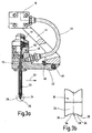
- Fig. 3a
- einen Schnitt durch den am Endglied des Roboters angelenkten Düsenkopf der Auftragvorrichtung;
- Fig. 3b
- eine Seitenansicht der Auftragsdüse in gegenüber Fig. 3a um 90° gedrehter vergrößerter Darstellung.
Claims (35)
- Vorrichtung zum Aufbringen eines Kunststoffstrangs auf eine Unterlage mit einem mit einem verfestigten flüssigen oder pastösen Kunststoff unter Druck beaufschlagbaren Düsenkopf (18), der eine vorzugsweise verschließbare Auftragsdüse (24) aufweist, wobei Düsenkopf (18) und Unterlage (14) mittels einer Roboteranordnung (10) so relativ zueinander bewegbar sind, daß die Auftragsdüse (24) entlang einer vorgegebenen Bahn (12) entlang der Unterlage (14) geführt ist, gekennzeichnet durch, eine UV-Lichtquelle (52) zur fotochemischen Aktivierung des Kunststoffs, die mindestens eine in Richtung Unterlage (14) und/oder in Richtung aus dem Düsenkopf (18) ausgebrachtem Kunststoff weisende Lichtaustrittsstelle aufweist.
- Vorrichtung nach Anspruch 1, dadurch gekennzeichnet, daß die UV-Lichtquelle (52), mindestens eine in den Strömungsweg des flüssigen oder pastösen Kunststoffs mündende Lichtaustrittsstelle aufweist.
- Vorrichtung nach Anspruch 1 oder 2, dadurch gekennzeichnet, daß die UV-Lichtquelle (52) mindestens eine in Bewegungsrichtung hinter dem Düsenkopf (18) angeordnete Lichtaustrittsstelle aufweist.
- Vorrichtung nach einem der Ansprüche 1 bis 3, dadurch gekennzeichnet, daß der Düsenkopf (18) am Endglied (16) der Roboteranordnung (10) angeordnet und mit dieser relativ zur Unterlage (14) entlang der vorgegebenen Bahn (12) bewegbar ist.
- Vorrichtung nach einem der Ansprüche 1 bis 4, dadurch gekennzeichnet, daß die UV-Lichtquelle (52) an der Roboteranordnung (10) oder am Düsenkopf (18) angeordnet und optisch mit der Lichtaustrittsstelle verbunden ist.
- Vorrichtung nach einem der Ansprüche 1 bis 5, dadurch gekennzeichnet, daß die UV-Lichtquelle über mindestens einen Lichtwellenleiter (65,66) mit der mindestens einen Lichtaustrittsstelle verbunden ist.
- Vorrichtung nach einem der Ansprüche 1 bis 6, dadurch gekennzeichnet, daß die UV-Lichtquelle (52) in einem in Richtung Unterlage und/oder in Richtung aus dem Düsenkopf (18) ausgebrachtem Kunststoff offenen Lampengehäuse (54) angeordnet ist.
- Vorrichtung nach Anspruch 7, dadurch gekennzeichnet, daß in dem Lampengehäuse (54) eine das UV-Licht zu einer Applikationsstelle entlang der Bewegungsbahn (12) lenkende Spiegelanordnung (60) angeordnet ist.
- Vorrichtung nach Anspruch 7 oder 8, dadurch gekennzeichnet, daß das Lampengehäuse (54) durch einen mit seinem Rand (56) gegen die Unterlage (14) anlegbaren, flexiblen Vorhang (58) begrenzt ist.
- Vorrichtung nach Anspruch 9, dadurch gekennzeichnet, daß der Vorhang (58) an seinem in Bewegungsrichtung (30) vorderen und rückwärtigen Randpartien eine randoffene Ausnehmung aufweist.
- Vorrichtung nach Anspruch 6, dadurch gekennzeichnet, daß die UV-Lichtquelle (52) eine von der UV-Lampe zur Lichtaustrittsstelle geführte flexible Lichtwellenleiteranordnung (66) aufweist.
- Vorrichtung nach Anspruch 11, dadurch gekennzeichnet, daß die Lichtwellenleiteranordnung mehrere Lichtwellenleiter (66) umfaßt, deren zur Unterlage (14) weisende Lichtaustrittsöffnungen in Bewegungsrichtung des Düsenkopfes (18) überwiegend hintereinander angeordnet sind.
- Vorrichtung nach einem der Ansprüche 1 bis 12, gekennzeichnet durch mindestens einen Lichtwellenleiter (65), der von der UV-Lichtquelle zu einer Lichtaustrittsstelle innerhalb des Düsenkopfes (18) führt.
- Vorrichtung nach einem der Ansprüche 1 bis 13, gekennzeichnet durch eine Heizvorrichtung zur Aufheizung des Kunststoffs.
- Vorrichtung nach Anspruch 14, dadurch gekennzeichnet, daß die Heizvorrichtung ein im Düsenkopf (18) angeordnetes Heizelement aufweist.
- Vorrichtung nach Anspruch 14 oder 15, dadurch gekennzeichnet, daß die Heizvorrichtung ein vorzugsweise an der Roboteranordnung (10) angeordnetes Heißluftgebläse aufweist.
- Vorrichtung nach einem der Ansprüche 14 bis 16, dadurch gekennzeichnet, daß die Heizvorrichtung mindestens ein vorzugsweise am Endglied (16) der Roboteranordnung (10) angeordnetes, in Richtung Unterlage (14) weisendes Heizelement (74,76) aufweist.
- Vorrichtung nach Anspruch 17, dadurch gekennzeichnet, daß das mindestens eine Heizelement (74) in Bewegungsrichtung hinter der Auftragsdüse (24) angeordnet ist.
- Vorrichtung nach Anspruch 17 oder 18, dadurch gekennzeichnet, daß das mindestens eine Heizelement (74) in Bewegungsrichtung (30) vor der Auftragsdüse (24) angeordnet ist.
- Vorrichtung nach einem der Ansprüche 17 bis 19, dadurch gekennzeichnet, daß das Heizelement (74,76) aus der Gruppe Heißluftdüse, IR- oder NIR-Heizer ausgebildet ist.
- Vorrichtung nach einem der Ansprüche 14 bis 20, dadurch gekennzeichnet, daß die Heizvorrichtung ein die Unterlage (14) zumindest entlang der Bewegungsbahn (12) aufheizendes Heizaggregat aufweist.
- Vorrichtung nach Anspruch 21, dadurch gekennzeichnet, daß das Heizaggregat als Induktionsheizer ausgebildet ist.
- Verfahren zum Aufbringen eines Kunststoffstrangs auf eine Unterlage, bei welchem der Kunststoff in flüssigem oder pastösem Zustand aus einer entlang der Unterlage geführten Düse auf die Unterlage aufgetragen und dort verfestigt wird, dadurch gekennzeichnet, daß der flüssige oder pastöse Kunststoff unmittelbar vor und/oder unmittelbar nach dem Auftrag auf die Unterlage mit UV-Licht bestrahlt und dabei fotochemisch zum Verfestigen aktiviert wird.
- Verfahren nach Anspruch 23, dadurch gekennzeichnet, daß der flüssige oder pastöse Kunststoff im Durchlauf entlang einem Strömungsweg mit dem UV-Licht bestrahlt wird.
- Verfahren nach Anspruch 24, dadurch gekennzeichnet, daß das UV-Licht über ein Lichtfenster in den Strömungsweg des flüssigen oder pastösen Kunststoffs eingeleitet wird.
- Verfahren nach Anspruch 25, dadurch gekennzeichnet, daß das Lichtfenster durch den vorbeiströmenden flüssigen oder pastösen Kunststoff benetzt und gereinigt wird.
- Verfahren nach einem der Ansprüche 24 bis 26, dadurch gekennzeichnet, daß das UV-Licht über einen Lichtwellenleiter zur Lichtaustrittsstelle geleitet wird.
- Verfahren nach einem der Ansprüche 23 bis 27, dadurch gekennzeichnet, daß das UV-Licht mit der Düse mitgeführt wird.
- Vorrichtung nach Anspruch 28, dadurch gekennzeichnet, daß das UV-Licht aus einer in Bewegungsrichtung hinter der Düse angeordneten Lichtaustrittstelle auf den flüssigen oder pastösen Kunststoff gerichtet wird.
- Verfahren nach einem der Ansprüche 23 bis 29, dadurch gekennzeichnet, daß der flüssige oder pastöse Kunststoff durch eine entlang einer Bewegungsbahn der Düse geführte UV-Lichtquelle im Vorbeibewegen mit UV-Licht bestrahlt wird.
- Verfahren nach einem der Ansprüche 23 bis 30, dadurch gekennzeichnet, daß der flüssige oder pastöse Kunststoff im erwärmten Zustand mit UV-Licht bestrahlt wird.
- Verfahren nach einem der Ansprüche 23 bis 31, dadurch gekennzeichnet, daß der flüssige oder pastöse Kunststoff vor dem Auftrag auf die Unterlage aufgeheizt wird.
- Verfahren nach einem der Ansprüche 23 bis 32, dadurch gekennzeichnet, daß der flüssige oder pastöse Kunststoff auf eine zumindest im Bereich der Bewegungsbahn vorgeheizte Unterlage aufgetragen und dabei aufgeheizt wird.
- Verwendung der Vorrichtung nach einem der Ansprüche 1 bis 22 und des Verfahrens nach einem der Ansprüche 23 bis 33 zum Aufbringen eines Dichtstoffs auf eine Bördelnaht an zwei Blechteilen.
- Verwendung nach Anspruch 33, dadurch gekennzeichnet, daß sich zwischen den Blechteilen im Bereich der Bördelnaht ein vorzugsweise thermisch verfestigbarer Klebstoff befindet.
Applications Claiming Priority (2)
| Application Number | Priority Date | Filing Date | Title |
|---|---|---|---|
| DE19936730 | 1999-08-06 | ||
| DE19936730A DE19936730A1 (de) | 1999-08-06 | 1999-08-06 | Vorrichtung und Verfahren zum Aufbringen eines Kunststoffstrangs auf eine Unterlage |
Publications (3)
| Publication Number | Publication Date |
|---|---|
| EP1074307A2 true EP1074307A2 (de) | 2001-02-07 |
| EP1074307A3 EP1074307A3 (de) | 2004-03-17 |
| EP1074307B1 EP1074307B1 (de) | 2008-06-11 |
Family
ID=7917179
Family Applications (1)
| Application Number | Title | Priority Date | Filing Date |
|---|---|---|---|
| EP00115013A Expired - Lifetime EP1074307B1 (de) | 1999-08-06 | 2000-07-24 | Vorrichtung und Verfahren zum Aufbringen eines Kunststoffstrangs auf eine Unterlage |
Country Status (3)
| Country | Link |
|---|---|
| EP (1) | EP1074307B1 (de) |
| AT (1) | ATE397979T1 (de) |
| DE (2) | DE19936730A1 (de) |
Cited By (8)
| Publication number | Priority date | Publication date | Assignee | Title |
|---|---|---|---|---|
| WO2008035116A3 (en) * | 2006-09-18 | 2008-06-26 | Ici Plc | Film formation and evaluation |
| WO2013139851A1 (de) * | 2012-03-22 | 2013-09-26 | Basf Se | Verfahren und vorrichtung zur herstellung von gehärteten lackschichten |
| WO2014131682A1 (de) * | 2013-02-27 | 2014-09-04 | Henkel Ag & Co. Kgaa | Verfahren zum herstellen einer versiegelung |
| US9339832B2 (en) | 2012-03-22 | 2016-05-17 | Basf Se | Spraygun for producing cured coating films and methods of use thereof |
| CN109590147A (zh) * | 2019-01-04 | 2019-04-09 | 福耀集团长春有限公司 | 一种汽车玻璃托架自动供料涂胶系统 |
| DE102018102238A1 (de) | 2018-02-01 | 2019-08-01 | Dr. Ing. H.C. F. Porsche Aktiengesellschaft | Verkleben und Abdichten von Naht- und Fügestellen |
| DE102018003345A1 (de) * | 2018-04-23 | 2019-10-24 | Kienle + Spiess Gmbh | Verfahren zur Herstellung von Lamellenpaketen sowie Auftrageinrichtung für ein Klebemittel zur Durchführung des Verfahrens |
| CN113522662A (zh) * | 2021-06-11 | 2021-10-22 | 张安娜 | 一种智慧社区相关led晶片贴片工件涂蜡处理装置 |
Families Citing this family (4)
| Publication number | Priority date | Publication date | Assignee | Title |
|---|---|---|---|---|
| DE10020679A1 (de) * | 2000-04-27 | 2001-11-08 | Basf Coatings Ag | Verfahren und Vorrichtung zum Abdichten von Fugen und Nähten in Kraftfahrzeugkarosserien |
| DE10141413B4 (de) * | 2001-08-23 | 2005-10-06 | Dannenhauer, Fritz, Dr. | Vorrichtung und Verfahren zur Applikation von Lacken mit energetisch initiierter Aushärtung |
| DE102005050135B4 (de) * | 2005-10-18 | 2016-09-29 | Sca Schucker Gmbh & Co. Kg | Materialauftragsvorrichtung für Reaktionsgemische |
| DE102007010636A1 (de) * | 2007-03-02 | 2008-10-30 | Intec Gmbh Lackiersysteme | Anlage zum Beschichten von Werkstücken insbesondere Lackieranlage |
Family Cites Families (14)
| Publication number | Priority date | Publication date | Assignee | Title |
|---|---|---|---|---|
| EP0094915B1 (de) * | 1982-05-19 | 1987-01-21 | Ciba-Geigy Ag | Härtbare, Metallocenkomplexe enthaltende Zusammensetzungen, daraus erhältliche aktivierte Vorstufen und deren Verwendung |
| DD259157A1 (de) * | 1986-04-01 | 1988-08-17 | Werkzeugmasch Forschzent | Schmelzklebe- und schweissvorrichtung |
| DE3737455A1 (de) * | 1986-11-06 | 1988-05-19 | Westinghouse Electric Corp | Einrichtung und verfahren zum erzeugen von farbmustern |
| DE3702999C2 (de) * | 1987-02-02 | 2003-03-06 | Siemens Ag | Vorrichtung zur Verarbeitung von UV-härtbaren Reaktionsharzmassen und deren Anwendung |
| DE3800628A1 (de) * | 1987-09-15 | 1989-03-23 | Schaft Volker | Verfahren und vorrichtung zum haerten von auf einem koerper aufgetragenen schichten |
| DE3809756C2 (de) * | 1988-03-23 | 1996-02-29 | Hoerauf Michael Maschf | Vorrichtung zum Auftragen von Klebstoff auf einen Behältermantel |
| IL88886A (en) * | 1989-01-05 | 1993-02-21 | Tamglass Oy | Method and system for applying a painted border around a windshield plate |
| DE3900861A1 (de) * | 1989-01-13 | 1990-07-19 | Ribnitz Peter | Verfahren zum herstellen einer dichtenden verbindungsrandpartie |
| DE3909688A1 (de) * | 1989-03-23 | 1990-09-27 | Espe Stiftung | Verfahren zum kleben oder vergiessen von substraten und vorrichtung zur seiner durchfuehrung |
| JP2669272B2 (ja) * | 1992-06-03 | 1997-10-27 | 信越化学工業株式会社 | 立体模様形成方法 |
| US5474799A (en) * | 1992-10-13 | 1995-12-12 | Reliance Electric Industrial Company | Apparatus and method for coating an electromagnetic coil |
| DE29517958U1 (de) * | 1995-11-13 | 1997-03-20 | Ernst Mühlbauer KG, 22547 Hamburg | Gerät für den inkrementalen Aufbau einer Zahnfüllung |
| DE19545800C2 (de) * | 1995-12-08 | 1997-10-23 | Int Schuh Maschinen Co Gmbh | Klebstoff-Auftragvorrichtung |
| US5948194A (en) * | 1998-06-12 | 1999-09-07 | Ford Global Technologies, Inc. | In-line microwave heating of adhesives |
-
1999
- 1999-08-06 DE DE19936730A patent/DE19936730A1/de not_active Withdrawn
-
2000
- 2000-07-24 DE DE50015197T patent/DE50015197D1/de not_active Expired - Lifetime
- 2000-07-24 EP EP00115013A patent/EP1074307B1/de not_active Expired - Lifetime
- 2000-07-24 AT AT00115013T patent/ATE397979T1/de not_active IP Right Cessation
Non-Patent Citations (1)
| Title |
|---|
| None |
Cited By (17)
| Publication number | Priority date | Publication date | Assignee | Title |
|---|---|---|---|---|
| WO2008035116A3 (en) * | 2006-09-18 | 2008-06-26 | Ici Plc | Film formation and evaluation |
| WO2013139851A1 (de) * | 2012-03-22 | 2013-09-26 | Basf Se | Verfahren und vorrichtung zur herstellung von gehärteten lackschichten |
| CN104203425A (zh) * | 2012-03-22 | 2014-12-10 | 巴斯夫欧洲公司 | 用于制备固化涂层的方法和设备 |
| US9339832B2 (en) | 2012-03-22 | 2016-05-17 | Basf Se | Spraygun for producing cured coating films and methods of use thereof |
| WO2014131682A1 (de) * | 2013-02-27 | 2014-09-04 | Henkel Ag & Co. Kgaa | Verfahren zum herstellen einer versiegelung |
| US11027496B2 (en) | 2018-02-01 | 2021-06-08 | Dr. Ing. H.C. F. Porsche Aktiengesellschaft | Adhesive bonding and sealing of seams and joints |
| DE102018102238A1 (de) | 2018-02-01 | 2019-08-01 | Dr. Ing. H.C. F. Porsche Aktiengesellschaft | Verkleben und Abdichten von Naht- und Fügestellen |
| CN110385233A (zh) * | 2018-04-23 | 2019-10-29 | 金勒+施皮斯有限公司 | 用于制造薄片组的方法以及用于用来执行所述方法的粘合剂的涂覆装置 |
| DE102018003345A1 (de) * | 2018-04-23 | 2019-10-24 | Kienle + Spiess Gmbh | Verfahren zur Herstellung von Lamellenpaketen sowie Auftrageinrichtung für ein Klebemittel zur Durchführung des Verfahrens |
| EP3562007A1 (de) * | 2018-04-23 | 2019-10-30 | Kienle + Spiess GmbH | Verfahren zur herstellung von lamellenpaketen sowie auftrageinrichtung für ein klebemittel zur durchführung des verfahrens |
| US11535021B2 (en) | 2018-04-23 | 2022-12-27 | Kienle + Spiess Gmbh | Method for producing lamination stacks and application device for an adhesive for performing the method |
| EP4216409A1 (de) * | 2018-04-23 | 2023-07-26 | Kienle + Spiess GmbH | Verfahren zur herstellung von lamellenpaketen sowie auftrageinrichtung für ein klebemittel zur durchführung des verfahrens |
| US12447729B2 (en) | 2018-04-23 | 2025-10-21 | Feintool International Holding Ag | Method for producing lamination stacks and application device for an adhesive for performing the method |
| CN109590147A (zh) * | 2019-01-04 | 2019-04-09 | 福耀集团长春有限公司 | 一种汽车玻璃托架自动供料涂胶系统 |
| CN109590147B (zh) * | 2019-01-04 | 2023-11-21 | 福耀集团长春有限公司 | 一种汽车玻璃托架自动供料涂胶系统 |
| CN113522662A (zh) * | 2021-06-11 | 2021-10-22 | 张安娜 | 一种智慧社区相关led晶片贴片工件涂蜡处理装置 |
| CN113522662B (zh) * | 2021-06-11 | 2023-12-05 | 张安娜 | 一种智慧社区相关led晶片贴片工件涂蜡处理装置 |
Also Published As
| Publication number | Publication date |
|---|---|
| DE50015197D1 (de) | 2008-07-24 |
| EP1074307B1 (de) | 2008-06-11 |
| ATE397979T1 (de) | 2008-07-15 |
| DE19936730A1 (de) | 2001-02-22 |
| EP1074307A3 (de) | 2004-03-17 |
Similar Documents
| Publication | Publication Date | Title |
|---|---|---|
| EP1074307B1 (de) | Vorrichtung und Verfahren zum Aufbringen eines Kunststoffstrangs auf eine Unterlage | |
| DE10038158C5 (de) | Verfahren und Vorrichtung zum Verbinden von Gegenständen mittels plastisch verformbarer Verbindungskörper | |
| DE10332939B4 (de) | Vorrichtung zum Reinigen eines Frontbereiches vor einem in einem Kraftfahrzeug eingebauten Abstandssensors | |
| DE10196087B3 (de) | Lichtleiter zum Laserschweißen | |
| EP2952316B1 (de) | Faserauftragwerkzeug, faserverlegevorrichtung, faserverlegeverfahren und herstellverfahren | |
| DE8438443U1 (de) | Vorrichtung zum Heißgasschweißen | |
| DE102016200522A1 (de) | Verfahren zur Herstellung dreidimensionaler Objekte und Vorrichtung zur Durchführung des besagten Verfahrens | |
| DE102004039684B4 (de) | Vorrichtung zur Aufbringung einer Leitpaste auf eine gekrümmte Harzglasscheibe | |
| EP3222407B1 (de) | Schweissautomat | |
| DE10019163A1 (de) | Ausströmvorrichtung zum Warmgas-Verschweißen von Kunststoffteilen und Verfahren zum Warmgas-Verschweißen von Kunststoffteilen | |
| DE19936716A1 (de) | Verfahren und Vorrichtung zum Auftragen eines Kunststoffstrangs auf eine Unterlage | |
| EP2658703B1 (de) | Verfahren und vorrichtung zur herstellung eines bauteils mittels spritzgiessens und schweissens | |
| DE3935562A1 (de) | Membran-formpresse | |
| EP0169188B1 (de) | Verfahren und Vorrichtung zum Anleimen oder Verkleben von Kantenmaterial an plattenförmige Werkstücke | |
| DE102005018727A1 (de) | Verfahren und Vorrichtung zum Verschweißen von zwei Werkstücken aus thermoplastischen Kunststoffen mittels Laserstrahlung | |
| DE102016216844A1 (de) | Verfahren für das Laserstrahl-Kunststoffschweißen sowie Vorrichtung | |
| DE19941996A1 (de) | Verfahren und Anordnung zum Aufheizen eines Bauteils entlang einer vorgegebenen Bahn | |
| DE202015005290U1 (de) | Düsenanordnung | |
| DE102007057177A1 (de) | Schweißvorrichtung | |
| EP0560171A1 (de) | Frei programmierbares Auftragsgerät für Medien wie Dichtmasse, Kleber etc. | |
| DE19545800C2 (de) | Klebstoff-Auftragvorrichtung | |
| DE10045994C2 (de) | Vorrichtung und Verfahren zum Aktivieren einer polymerisierbaren Flüssigkeit | |
| DE102007031555A1 (de) | Reinigungsvorrichtung für eine Sprühvorrichtung | |
| DE10312381A1 (de) | Verfahren zur Trocknung einer Lackierung auf einem Objekt | |
| DE10257112A1 (de) | Laserstrahlbearbeitungsvorrichtung zum Fügen und/oder Beschichten von Kunststoffen |
Legal Events
| Date | Code | Title | Description |
|---|---|---|---|
| PUAI | Public reference made under article 153(3) epc to a published international application that has entered the european phase |
Free format text: ORIGINAL CODE: 0009012 |
|
| AK | Designated contracting states |
Kind code of ref document: A2 Designated state(s): AT BE CH CY DE DK ES FI FR GB GR IE IT LI LU MC NL PT SE |
|
| AX | Request for extension of the european patent |
Free format text: AL;LT;LV;MK;RO;SI |
|
| RAP1 | Party data changed (applicant data changed or rights of an application transferred) |
Owner name: SCA SCHUCKER GMBH & CO. Owner name: VOLKSWAGEN AKTIENGESELLSCHAFT |
|
| RAP1 | Party data changed (applicant data changed or rights of an application transferred) |
Owner name: VOLKSWAGEN AKTIENGESELLSCHAFT Owner name: SCA SCHUCKER GMBH |
|
| RAP1 | Party data changed (applicant data changed or rights of an application transferred) |
Owner name: SCA SCHUCKER GMBH & CO. Owner name: VOLKSWAGEN AKTIENGESELLSCHAFT |
|
| PUAL | Search report despatched |
Free format text: ORIGINAL CODE: 0009013 |
|
| AK | Designated contracting states |
Kind code of ref document: A3 Designated state(s): AT BE CH CY DE DK ES FI FR GB GR IE IT LI LU MC NL PT SE |
|
| AX | Request for extension of the european patent |
Extension state: AL LT LV MK RO SI |
|
| 17P | Request for examination filed |
Effective date: 20040917 |
|
| AKX | Designation fees paid |
Designated state(s): AT BE CH CY DE DK ES FI FR GB GR IE IT LI LU MC NL PT SE |
|
| 17Q | First examination report despatched |
Effective date: 20070417 |
|
| GRAP | Despatch of communication of intention to grant a patent |
Free format text: ORIGINAL CODE: EPIDOSNIGR1 |
|
| GRAS | Grant fee paid |
Free format text: ORIGINAL CODE: EPIDOSNIGR3 |
|
| GRAA | (expected) grant |
Free format text: ORIGINAL CODE: 0009210 |
|
| AK | Designated contracting states |
Kind code of ref document: B1 Designated state(s): AT BE CH CY DE DK ES FI FR GB GR IE IT LI LU MC NL PT SE |
|
| REG | Reference to a national code |
Ref country code: GB Ref legal event code: FG4D Free format text: NOT ENGLISH |
|
| REG | Reference to a national code |
Ref country code: CH Ref legal event code: EP |
|
| REF | Corresponds to: |
Ref document number: 50015197 Country of ref document: DE Date of ref document: 20080724 Kind code of ref document: P |
|
| REG | Reference to a national code |
Ref country code: IE Ref legal event code: FG4D Free format text: LANGUAGE OF EP DOCUMENT: GERMAN |
|
| PG25 | Lapsed in a contracting state [announced via postgrant information from national office to epo] |
Ref country code: FI Free format text: LAPSE BECAUSE OF FAILURE TO SUBMIT A TRANSLATION OF THE DESCRIPTION OR TO PAY THE FEE WITHIN THE PRESCRIBED TIME-LIMIT Effective date: 20080611 |
|
| PG25 | Lapsed in a contracting state [announced via postgrant information from national office to epo] |
Ref country code: NL Free format text: LAPSE BECAUSE OF FAILURE TO SUBMIT A TRANSLATION OF THE DESCRIPTION OR TO PAY THE FEE WITHIN THE PRESCRIBED TIME-LIMIT Effective date: 20080611 |
|
| NLV1 | Nl: lapsed or annulled due to failure to fulfill the requirements of art. 29p and 29m of the patents act | ||
| PG25 | Lapsed in a contracting state [announced via postgrant information from national office to epo] |
Ref country code: ES Free format text: LAPSE BECAUSE OF FAILURE TO SUBMIT A TRANSLATION OF THE DESCRIPTION OR TO PAY THE FEE WITHIN THE PRESCRIBED TIME-LIMIT Effective date: 20080922 Ref country code: PT Free format text: LAPSE BECAUSE OF FAILURE TO SUBMIT A TRANSLATION OF THE DESCRIPTION OR TO PAY THE FEE WITHIN THE PRESCRIBED TIME-LIMIT Effective date: 20081111 Ref country code: SE Free format text: LAPSE BECAUSE OF FAILURE TO SUBMIT A TRANSLATION OF THE DESCRIPTION OR TO PAY THE FEE WITHIN THE PRESCRIBED TIME-LIMIT Effective date: 20080911 |
|
| REG | Reference to a national code |
Ref country code: IE Ref legal event code: FD4D |
|
| REG | Reference to a national code |
Ref country code: CH Ref legal event code: PL |
|
| PG25 | Lapsed in a contracting state [announced via postgrant information from national office to epo] |
Ref country code: MC Free format text: LAPSE BECAUSE OF NON-PAYMENT OF DUE FEES Effective date: 20080731 |
|
| PLBE | No opposition filed within time limit |
Free format text: ORIGINAL CODE: 0009261 |
|
| STAA | Information on the status of an ep patent application or granted ep patent |
Free format text: STATUS: NO OPPOSITION FILED WITHIN TIME LIMIT |
|
| PG25 | Lapsed in a contracting state [announced via postgrant information from national office to epo] |
Ref country code: DK Free format text: LAPSE BECAUSE OF FAILURE TO SUBMIT A TRANSLATION OF THE DESCRIPTION OR TO PAY THE FEE WITHIN THE PRESCRIBED TIME-LIMIT Effective date: 20080611 Ref country code: IE Free format text: LAPSE BECAUSE OF FAILURE TO SUBMIT A TRANSLATION OF THE DESCRIPTION OR TO PAY THE FEE WITHIN THE PRESCRIBED TIME-LIMIT Effective date: 20080611 |
|
| 26N | No opposition filed |
Effective date: 20090312 |
|
| GBPC | Gb: european patent ceased through non-payment of renewal fee |
Effective date: 20080911 |
|
| PG25 | Lapsed in a contracting state [announced via postgrant information from national office to epo] |
Ref country code: CH Free format text: LAPSE BECAUSE OF NON-PAYMENT OF DUE FEES Effective date: 20080731 Ref country code: LI Free format text: LAPSE BECAUSE OF NON-PAYMENT OF DUE FEES Effective date: 20080731 |
|
| REG | Reference to a national code |
Ref country code: FR Ref legal event code: ST Effective date: 20090529 |
|
| PG25 | Lapsed in a contracting state [announced via postgrant information from national office to epo] |
Ref country code: IT Free format text: LAPSE BECAUSE OF FAILURE TO SUBMIT A TRANSLATION OF THE DESCRIPTION OR TO PAY THE FEE WITHIN THE PRESCRIBED TIME-LIMIT Effective date: 20080611 |
|
| PG25 | Lapsed in a contracting state [announced via postgrant information from national office to epo] |
Ref country code: FR Free format text: LAPSE BECAUSE OF NON-PAYMENT OF DUE FEES Effective date: 20080731 Ref country code: AT Free format text: LAPSE BECAUSE OF NON-PAYMENT OF DUE FEES Effective date: 20080724 |
|
| PG25 | Lapsed in a contracting state [announced via postgrant information from national office to epo] |
Ref country code: GB Free format text: LAPSE BECAUSE OF NON-PAYMENT OF DUE FEES Effective date: 20080911 |
|
| PG25 | Lapsed in a contracting state [announced via postgrant information from national office to epo] |
Ref country code: LU Free format text: LAPSE BECAUSE OF NON-PAYMENT OF DUE FEES Effective date: 20080724 |
|
| PG25 | Lapsed in a contracting state [announced via postgrant information from national office to epo] |
Ref country code: BE Free format text: LAPSE BECAUSE OF NON-PAYMENT OF DUE FEES Effective date: 20080731 Ref country code: CY Free format text: LAPSE BECAUSE OF FAILURE TO SUBMIT A TRANSLATION OF THE DESCRIPTION OR TO PAY THE FEE WITHIN THE PRESCRIBED TIME-LIMIT Effective date: 20080611 |
|
| PG25 | Lapsed in a contracting state [announced via postgrant information from national office to epo] |
Ref country code: GR Free format text: LAPSE BECAUSE OF FAILURE TO SUBMIT A TRANSLATION OF THE DESCRIPTION OR TO PAY THE FEE WITHIN THE PRESCRIBED TIME-LIMIT Effective date: 20080912 |
|
| REG | Reference to a national code |
Ref country code: DE Ref legal event code: R081 Ref document number: 50015197 Country of ref document: DE Owner name: VOLKSWAGEN AKTIENGESELLSCHAFT, DE Free format text: FORMER OWNER: SCA SCHUCKER GMBH & CO., VOLKSWAGEN AKTIENGESELLSCHAFT, , DE Effective date: 20110221 Ref country code: DE Ref legal event code: R081 Ref document number: 50015197 Country of ref document: DE Owner name: VOLKSWAGEN AKTIENGESELLSCHAFT, DE Free format text: FORMER OWNERS: SCA SCHUCKER GMBH & CO., 75015 BRETTEN, DE; VOLKSWAGEN AKTIENGESELLSCHAFT, 38440 WOLFSBURG, DE Effective date: 20110221 |
|
| PGFP | Annual fee paid to national office [announced via postgrant information from national office to epo] |
Ref country code: DE Payment date: 20160731 Year of fee payment: 17 |
|
| REG | Reference to a national code |
Ref country code: DE Ref legal event code: R119 Ref document number: 50015197 Country of ref document: DE |
|
| PG25 | Lapsed in a contracting state [announced via postgrant information from national office to epo] |
Ref country code: DE Free format text: LAPSE BECAUSE OF NON-PAYMENT OF DUE FEES Effective date: 20180201 |