EP1074762A2 - Apparatus and method for rotor damping - Google Patents
Apparatus and method for rotor damping Download PDFInfo
- Publication number
- EP1074762A2 EP1074762A2 EP00306571A EP00306571A EP1074762A2 EP 1074762 A2 EP1074762 A2 EP 1074762A2 EP 00306571 A EP00306571 A EP 00306571A EP 00306571 A EP00306571 A EP 00306571A EP 1074762 A2 EP1074762 A2 EP 1074762A2
- Authority
- EP
- European Patent Office
- Prior art keywords
- damper
- ring
- rotor
- circumferential surface
- groove
- Prior art date
- Legal status (The legal status is an assumption and is not a legal conclusion. Google has not performed a legal analysis and makes no representation as to the accuracy of the status listed.)
- Granted
Links
Images


Classifications
-
- F—MECHANICAL ENGINEERING; LIGHTING; HEATING; WEAPONS; BLASTING
- F01—MACHINES OR ENGINES IN GENERAL; ENGINE PLANTS IN GENERAL; STEAM ENGINES
- F01D—NON-POSITIVE DISPLACEMENT MACHINES OR ENGINES, e.g. STEAM TURBINES
- F01D5/00—Blades; Blade-carrying members; Heating, heat-insulating, cooling or antivibration means on the blades or the members
- F01D5/12—Blades
- F01D5/22—Blade-to-blade connections, e.g. for damping vibrations
- F01D5/24—Blade-to-blade connections, e.g. for damping vibrations using wire or the like
-
- F—MECHANICAL ENGINEERING; LIGHTING; HEATING; WEAPONS; BLASTING
- F16—ENGINEERING ELEMENTS AND UNITS; GENERAL MEASURES FOR PRODUCING AND MAINTAINING EFFECTIVE FUNCTIONING OF MACHINES OR INSTALLATIONS; THERMAL INSULATION IN GENERAL
- F16F—SPRINGS; SHOCK-ABSORBERS; MEANS FOR DAMPING VIBRATION
- F16F15/00—Suppression of vibrations in systems; Means or arrangements for avoiding or reducing out-of-balance forces, e.g. due to motion
- F16F15/10—Suppression of vibrations in rotating systems by making use of members moving with the system
- F16F15/12—Suppression of vibrations in rotating systems by making use of members moving with the system using elastic members or friction-damping members, e.g. between a rotating shaft and a gyratory mass mounted thereon
- F16F15/121—Suppression of vibrations in rotating systems by making use of members moving with the system using elastic members or friction-damping members, e.g. between a rotating shaft and a gyratory mass mounted thereon using springs as elastic members, e.g. metallic springs
- F16F15/1213—Spiral springs, e.g. lying in one plane, around axis of rotation
-
- F—MECHANICAL ENGINEERING; LIGHTING; HEATING; WEAPONS; BLASTING
- F16—ENGINEERING ELEMENTS AND UNITS; GENERAL MEASURES FOR PRODUCING AND MAINTAINING EFFECTIVE FUNCTIONING OF MACHINES OR INSTALLATIONS; THERMAL INSULATION IN GENERAL
- F16F—SPRINGS; SHOCK-ABSORBERS; MEANS FOR DAMPING VIBRATION
- F16F15/00—Suppression of vibrations in systems; Means or arrangements for avoiding or reducing out-of-balance forces, e.g. due to motion
- F16F15/10—Suppression of vibrations in rotating systems by making use of members moving with the system
- F16F15/12—Suppression of vibrations in rotating systems by making use of members moving with the system using elastic members or friction-damping members, e.g. between a rotating shaft and a gyratory mass mounted thereon
- F16F15/121—Suppression of vibrations in rotating systems by making use of members moving with the system using elastic members or friction-damping members, e.g. between a rotating shaft and a gyratory mass mounted thereon using springs as elastic members, e.g. metallic springs
- F16F15/124—Elastomeric springs
- F16F15/126—Elastomeric springs consisting of at least one annular element surrounding the axis of rotation
-
- Y—GENERAL TAGGING OF NEW TECHNOLOGICAL DEVELOPMENTS; GENERAL TAGGING OF CROSS-SECTIONAL TECHNOLOGIES SPANNING OVER SEVERAL SECTIONS OF THE IPC; TECHNICAL SUBJECTS COVERED BY FORMER USPC CROSS-REFERENCE ART COLLECTIONS [XRACs] AND DIGESTS
- Y10—TECHNICAL SUBJECTS COVERED BY FORMER USPC
- Y10S—TECHNICAL SUBJECTS COVERED BY FORMER USPC CROSS-REFERENCE ART COLLECTIONS [XRACs] AND DIGESTS
- Y10S416/00—Fluid reaction surfaces, i.e. impellers
- Y10S416/50—Vibration damping features
Definitions
- the present invention relates generally to rotors, and more particularly to damping unwanted rotor vibrations.
- Rotors are the rotatable portions of rotary machines, and rotary machines include, without limitation, X-ray tubes, a centrifugal compressor, a steam turbine (including a turbine portion thereof) used by a power utility company, and a gas turbine (including a compressor portion or a turbine portion thereof) used as an aircraft engine or used by a power utility company.
- the rotor may include rotor blades attached to, and extending radially-outward from, a shaft, or the rotor may be a monolithic blisk having shaft and blade portions.
- the damper-ring groove is a circumferential, radially-inward-facing groove on the shaft or shaft-portion of the rotor with the groove being coaxially aligned with the longitudinal axis of the rotor.
- the groove may have two longitudinally-spaced-apart side walls or, in the case of a tapered shaft, the groove may have a single side wall.
- the split-ring damper is a metallic ring having a single, radially-aligned through-cut.
- the weight, flexibility (Young's modulus), and surface friction characteristics of the split-ring damper are chosen (by experiment, computer analysis, and/or closed-form equations) to provide the most damping for a particular amplitude of one rotor vibrational mode of one natural vibrational frequency which typically corresponds to an expected maximum amplitude of a dominant vibrational mode of an excitation frequency which is closest to steady-state rotor operation.
- the split-ring design of the damper provides ease of installation in the damper-ring groove and allows frictional damping (by microslippage) between the outer circumferential surface of the split-ring damper and the rotor. Such damping is less effective or ineffective to dampen vibrations below the expected maximum amplitude, such as small-amplitude vibrations which may lead to fatigue failure of the rotor. What is needed is improved rotor damping.
- apparatus for damping a rotor includes at least a first and a second damper ring wherein the outer diameter of the second damper ring is generally equal to the inner diameter of the first damper ring.
- a rotor assembly includes a rotor having a damper-ring groove and includes the previously-described at least first and second damper rings positioned in the damper-ring groove.
- apparatus in a third embodiment of the invention, includes a damper-ring assembly having an inner damper ring, an outer damper ring, and a viscoelastic layer positioned radially between and bonded to the inner and outer damper rings.
- a rotor assembly in a fourth embodiment, includes a rotor having a damper-ring groove and includes the previously-described damper-ring assembly positioned in the damper-ring groove.
- a rotor assembly in a fifth embodiment of the invention, includes a rotor having a damper-ring groove and includes a damper-ring assembly positioned in the damper-ring groove, wherein the damper-ring assembly has an outer damper ring and has a viscoelastic layer positioned radially between and bonded to the outer damper ring and the rotor.
- a damper ring in a sixth embodiment of the invention, includes a generally ring-shaped housing having a hollow portion and includes particulate matter located within the hollow portion of the housing.
- a rotor assembly in a seventh embodiment, includes a rotor having a damper-ring groove and includes the previously-mentioned damper ring disposed in the damper-ring groove.
- apparatus in an eighth embodiment, includes single-wire strands twisted together to define a cable, wherein the cable has a shape of a split ring.
- a rotor assembly includes a rotor having a damper-ring groove and includes the previously-described cable positioned in the damper-ring groove.
- the known single-ring design of the prior art provides frictional damping between the outer circumferential surface of the ring and the rotor only for large-amplitude vibrations.
- the outer circumferential surface of the inner ring and the inner circumferential surface of the outer ring undergo microslippage and hence frictional damping in response to small-amplitude vibrations, and, for large-amplitude vibrations, there is added thereto the frictional damping of the outer circumferential surface of the outer ring with the rotor.
- the viscoelastic layer provides damping in the form of viscous damping for smaller-amplitude vibrations, and, for larger-amplitude vibrations, there is added thereto the frictional damping of ring-rotor contact or ring-ring contact.
- the particulate matter provides particulate frictional damping for smaller-amplitude vibrations, and, for larger-amplitude vibrations, there is added thereto the frictional damping of the ring's housing with the rotor.
- the twisted single-wire strands provide frictional damping between strands for smaller-amplitude vibrations, and, for larger-amplitude vibrations, there is added thereto the frictional damping of the cable with the rotor.
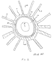
- FIGS 1-2 show a prior-art rotor 10, of an aircraft gas turbine engine, including a shaft portion 12 and blade portions 14.
- Rotor 10 is of monolithic construction (i.e., a blisk), although different prior-art rotors are designed wherein individual rotor blades are attached to a separate rotor.
- the rotor 10 has a longitudinal axis 16 and is shown with a damper-ring groove 18 having first and second side walls 20 and 22.
- a damper ring 24 is shown installed in the damper-ring groove 18. It is noted that, for a tapered shaft or shaft portion, only one side wall is needed to prevent longitudinal movement of a damper ring in a damper-ring groove, as is known to the artisan.
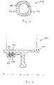
- FIG. 3 An embodiment of apparatus 126 of the invention is shown in Figure 3, and an embodiment of a rotor assembly 128 of the invention is shown in Figure 4 which includes the apparatus 126 of Figure 3.
- the apparatus 126 is for damping a rotor 110 undergoing a vibration, wherein the rotor 110 has a damper-ring groove 118.
- the apparatus 126 includes at least a first and a second damper ring 130 and 132.
- the first damper ring 130 is disposable in the damper-ring groove 118, has an inner diameter and an inner circumferential surface 134, and has an outer diameter and an outer circumferential surface 136.
- the second damper ring 132 is disposable in the damper-ring groove 118, has an outer diameter, and has an outer circumferential surface 138.
- the outer diameter of the second damper ring 132 is generally equal to the inner diameter of the first damper ring 130.
- the inner circumferential surface 134 of the first damper ring 130 and the outer circumferential surface 138 of the second damper ring 132 unattachedly contact each other when the first and second damper rings 130 and 132 are disposed in the damper-ring groove 118.
- the first and second damper rings 130 and 132 experience frictional damping at the contact of the second damper ring 132 with the first damper ring 130 when the rotor 110 undergoes the previously-mentioned vibration.
- the first and second damper rings 130 and 132 are split rings.
- the outer circumferential surface 136 of the first damper ring 130 unattachedly contacts the rotor 110 when the first and second damper rings 130 and 132 are disposed in the damper-ring groove 118, and the first damper ring 130 experiences frictional damping at the contact of the first damper ring 130 with the rotor 110 when the rotor 110 undergoes the previously-mentioned vibration.
- the rotor assembly 128, of the embodiment of the invention shown in Figure 4, includes a rotor 110 having a damper-ring groove 118 and includes at least a first and a second damper ring 130 and 132.
- the first damper ring 130 is disposed in the damper-ring groove 118 and has an inner circumferential surface 134 and an outer circumferential surface 136.
- the second damper ring 132 is disposed in the damper-ring groove 118 and has an outer circumferential surface 138.
- the inner circumferential surface 134 of the first damper ring 130 and the outer circumferential surface 138 of the second damper ring 132 unattachedly contact each other.
- the first and second damper rings 130 and 132 are split rings.
- the split in the first damper ring 130 is radially offset with respect to the split in the second damper ring 132 at the time of installation, such radial offset being shown in Figure 3.
- the outer circumferential surface 136 of the first damper ring 130 unattachedly contacts the rotor 110.
- the rotor is not limited to a rotor of an aircraft gas turbine engine, and may be a rotor of any machine such as, but not limited to, an X-ray tube, a centrifugal compressor, a steam turbine (including a turbine portion thereof) used by a power utility company, and a gas turbine (including a compressor portion or a turbine portion thereof) used by a power utility company.
- first and second (or more) damper rings 130 and 132 One technique for designing first and second (or more) damper rings 130 and 132 is to first consider the concentric rings as a single thick ring. Then, the single thick ring is designed using the known techniques of designing a prior-art single damper ring for a rotor having a damper-ring groove, wherein the single thick ring undergoes significant frictional damping with the rotor for an expected maximum amplitude of vibration.
- the single thick ring is broken into first and second (or more) damper rings 130 and 132, using the same techniques for designing the single thick ring, such that the second (inner) ring undergoes microslippage with respect to the first (outer) ring and the first (outer) ring undergoes microslippage with respect to the rotor at the expected maximum amplitude of vibration and such that only the second (inner) ring undergoes microslippage with respect to the first (outer) ring for a smaller amplitude of vibration.
- This will provide significant frictional damping at lower vibrational amplitudes to reduce the risk of small-amplitude fatigue failure of the rotor where the known single-ring design provides no damping.
- This also will provide damping at the expected maximum amplitude of vibration with such damping being greater (because of the inter-ring microslippage of two or more rings) than that of the known single ring design of the prior art.
- a first expression of a method of the invention is for damping a vibration of a rotor 110 having a damper-ring groove 118 and includes steps a) through d).
- Step a) includes obtaining a first damper ring 130 having an inner diameter.
- Step b) includes obtaining a second damper ring 132 having an outer diameter which is generally equal to the inner diameter of the first damper ring 130.
- Step c) includes disposing the first damper ring 130 in the damper-ring groove 118.
- Step d) includes disposing the second damper ring in the damper-ring groove 118 such that the inner circumferential surface 134 of the first damper ring 130 and the outer circumferential surface 138 of the second damper ring unattachedly contact each other and such that the first and second damper rings 130 and 132 experience frictional damping at the contact of the second damper ring 132 with the first damper ring 130 when the rotor undergoes the previously-mentioned vibration.
- step a) includes obtaining a first damper ring 130 which is a split ring
- step b) includes obtaining a second damper ring 132 which is a split ring
- the damper-ring groove 118 has a groove diameter
- step a) includes obtaining a first damper ring 130 having an outer diameter which is generally equal to the groove diameter of the damper-ring groove 118.
- step c) includes disposing the first damper ring 130 in the damper-ring groove 118 such that outer circumferential surface 136 of the first damper ring 130 unattachedly contacts the rotor 110 and such that the rotor 110 and the first damper ring 130 experience frictional damping at the contact of the rotor 110 with the damper ring 130 when the rotor 110 undergoes the previously-mentioned vibration.
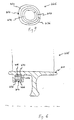
- FIG. 5 Another embodiment of apparatus 226 of the invention is shown in Figure 5, and an embodiment of a rotor assembly 228 of the invention is shown in Figure 6 which includes the apparatus 226 of Figure 5.
- the apparatus 226 is for damping a rotor 210 undergoing a vibration, wherein the rotor 210 has a damper-ring groove 218.
- the apparatus 226 includes a damper-ring assembly 240 having an inner damper ring 232, an outer damper ring 230, and a viscoelastic layer 242 disposed radially between and bonded to the inner and outer damper rings 232 and 230.
- Examples of viscoelastic materials suitable for the viscoelastic layer 242 include, without limitation, polymers and plastics.
- the damper ring assembly 240 is disposable in the damper-ring groove 218.
- the damper-ring assembly 240 is a split-ring assembly.
- the split in the inner damper ring 232 is radially offset with respect to the split in the outer damper ring 230, as seen in Figure 5.
- the outer damper ring 230 has an outer circumferential surface 236 which unattachedly contacts the rotor 210 when the damper-ring assembly 240 is disposed in the damper-ring groove 218, wherein the rotor 210 and the outer damper ring 230 experience frictional damping at the contact of the outer damper ring 230 with the rotor 210 when the rotor 210 undergoes the previously-mentioned vibration, and wherein the outer and inner damper rings 230 and 232 experience viscous damping from the viscoelastic layer 242 when the rotor undergoes the previously-mentioned vibration.
- the rotor assembly 228, of the embodiment of the invention shown in Figure 6, includes a rotor 210 having a damper-ring groove 218 and includes a damper-ring assembly 240 disposed in the damper-ring groove 218.
- the damper-ring assembly 240 has an inner damper ring 232, an outer damper ring 230, and a viscoelastic layer 242 disposed radially between and bonded to the inner and outer damper rings 232 and 230.
- the damper-ring assembly 240 is a split-ring assembly.
- the split in the inner damper ring 232 is radially offset with respect to the split in the outer damper ring 230, such radial offset being shown in Figure 5.
- the outer damper ring 230 has an outer circumferential surface 236 which unattachedly contacts the rotor 210.
- Viscoelastic layers can be designed by the artisan such that viscous damping is provided by the viscoelastic layer 242 at small (and large) amplitudes of vibration and such that frictional damping is provided between the outer damper ring 230 and the rotor 210 only at large amplitudes of vibration.
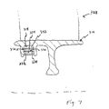
- the rotor assembly 328 includes a rotor 310 having a damper-ring groove 318 and includes a damper-ring assembly 340 disposed in the damper-ring groove 318.
- the damper-ring assembly 340 includes an outer damper ring 330 and includes a viscoelastic layer 342 disposed radially between and bonded to the outer damper ring 330 and the rotor 310.
- the rotor assembly 328 also includes an inner damper ring 332 disposed in the damper-ring groove 318, wherein the outer damper ring 330 has an inner circumferential surface 334, wherein the inner damper ring 332 has an outer circumferential surface 338, and wherein the inner circumferential surface 334 of the outer damper ring 330 and the outer circumferential surface 338 of the inner damper ring 332 unattachedly contact each other.
- the damper-ring assembly 340 is a split-ring assembly
- the inner damper ring 332 is a split ring.
- Viscoelastic layers can be designed by the artisan such that viscous damping is provided by the viscoelastic layer 342 at small (and larger) amplitudes of vibration and such that frictional damping is provided between the rings 332 and 330 only at larger amplitudes of vibration.
- FIG 8 An embodiment of a damper ring 424 of the invention is shown in Figure 8, and an embodiment of a rotor assembly 428 of the invention is shown in Figure 9 which includes the damper ring 424 of Figure 8.
- the damper ring 424 is for damping a rotor 410 undergoing a vibration, wherein the rotor 410 has a damper-ring groove 418.
- the damper ring 424 includes a generally ring-shaped housing 444 disposable in the damper-ring groove 418 and having a hollow portion 446, and the damper ring 424 includes particulate matter 448 disposed within the hollow portion 446 of the housing 444.
- particulate matter is any matter comprising, consisting essentially of, or consisting of particles having a volume of less than ten cubic millimeters.
- particulate matter include, without limitation, sand, polymer pellets, metal powder, and ceramic powder.
- the housing 444 has a split-ring shape, and the hollow portion 446 has an annular shape which is generally coaxially aligned with the housing 444.
- the housing 444 has an outer circumferential surface 436, wherein the outer circumferential surface 436 of the housing 444 unattachedly contacts the rotor 410 when the housing 444 is disposed in the damper-ring groove 418.
- the rotor assembly 428 includes a rotor 410 having a damper-ring groove 418 and includes a damper ring 424.
- the damper ring 424 includes a generally ring-shaped housing 444 disposed in the damper-ring groove 418 and having a hollow portion 446, and the damper ring 424 includes particulate matter 448 disposed within the hollow portion 446 of the housing 444.
- the housing 444 has a split-ring shape
- the hollow portion 446 has an annular shape which is generally coaxially aligned with the housing 444.
- the housing 444 has an outer circumferential surface 436, wherein the outer circumferential surface 436 of the housing 444 unattachedly contacts the rotor 410.
- the composition, particulate size, and total volume of the particulate matter 448 can be chosen by the artisan to provide frictional damping between particles at small (and large) amplitudes of vibration while providing frictional damping between the housing 444 and the rotor 410 only at large amplitudes of vibration.
- FIG. 10 Another embodiment of apparatus 526 of the invention is shown in Figure 10, and an embodiment of a rotor assembly 528 of the invention is shown in Figure 11 which includes the apparatus 526 of Figure 10.
- the apparatus 526 is for damping a rotor 510 undergoing a vibration, wherein the rotor 510 has a damper-ring groove 518.
- the apparatus 526 includes a plurality of single-wire strands 550 twisted together to define a cable 552, wherein the cable 552 has a shape of a split ring, and wherein the cable 552 is disposable in the damper-ring groove 518.
- Examples of wire strands include, without limitation, steel wire strands and tungsten wire strands. In one design, at least some of the single-wire strands 550 unattachedly contact the rotor 510 when the cable 552 is disposed in the damper-ring groove 518.
- the rotor assembly 528 includes a rotor 510 having a damper-ring groove 518 and includes a plurality of single-wire strands 550 twisted together to define a cable 552, wherein the cable 552 has a shape of a split ring, and wherein the cable 552 is disposed in the damper-ring groove 518.
- the single-wire strands 550 unattachedly contact the rotor 510.
- the number, size, composition, and surface friction characteristics of the wire strands 550 can be chosen by the artisan to provide inter-strand frictional damping at small (and large) amplitudes of vibration while providing frictional damping between the cable 552 and the rotor 510 only at large amplitudes of vibration.
- the frictional or viscous damping of an inner ring can be designed to provide damping for another vibrational mode different from a dominant vibrational mode which is damped by an outer ring or to provide damping for a natural frequency of vibration separate from a natural frequency of vibration closest to steady-state conditions which is damped by the outer ring.
- the various described multi-ring, viscoelastic layer, particulate matter, and cable embodiments can be used mainly alone as previously-described. However, in some applications, such embodiment may be used in any combination or combinations, as can be practiced by those skilled in the art.
Landscapes
- Engineering & Computer Science (AREA)
- General Engineering & Computer Science (AREA)
- Mechanical Engineering (AREA)
- Physics & Mathematics (AREA)
- Acoustics & Sound (AREA)
- Aviation & Aerospace Engineering (AREA)
- Turbine Rotor Nozzle Sealing (AREA)
- Structures Of Non-Positive Displacement Pumps (AREA)
Abstract
Description
Claims (10)
- Apparatus (126) for damping a rotor (110) undergoing a vibration, said rotor having a damper-ring groove (118), and said apparatus comprising at least a first and a second damper ring (130 and 132), wherein said first damper ring (130) is disposable in said damper-ring groove, has an inner diameter and an inner circumferential surface (134), and has an outer diameter and an outer circumferential surface (136); wherein said second damper ring (132) is disposable in said damper-ring groove, has an outer diameter, and has an outer circumferential surface (138); wherein said outer diameter of said second damper ring is generally equal to the inner diameter of said first damper ring; wherein said inner circumferential surface of said first damper ring and said outer circumferential surface of said second damper ring unattachedly contact each other when said first and second damper rings are disposed in said damper-ring groove; and wherein said first and second damper rings experience frictional damping at said contact of said second damper ring with said first damper ring when said rotor undergoes said vibration.
- A rotor assembly (128) comprising:a) a rotor (110) having a damper-ring groove (118); andb) at least a first and a second damper ring (130 and 132), wherein said first damper ring (130) is disposed in said damper-ring groove and has an inner circumferential surface (134) and an outer circumferential surface (136), wherein said second damper ring (132) is disposed in said damper-ring groove and has an outer circumferential surface (138), wherein said inner circumferential surface of said first damper ring and said outer circumferential surface of said second damper ring unattachedly contact each other.
- A method for damping a vibration of a rotor (110), wherein said rotor has a damper-ring groove (118), and wherein said method comprises the steps of:a) obtaining a first damper ring (130) having an inner diameter;b) obtaining a second damper ring (132) having an outer diameter which is generally equal to the inner diameter of said first damper ring;c) disposing said first damper ring in said damper-ring groove; andd) disposing said second damper ring in said damper-ring groove such that the inner circumferential surface (134) of said first damper ring and the outer circumferential surface (138) of said second damper ring unattachedly contact each other and such that said first and second damper rings experience frictional damping at said contact of said second damper ring with said first damper ring when said rotor undergoes said vibration.
- Apparatus (226) for damping a rotor (210) undergoing a vibration, said rotor having a damper-ring groove (218), and said apparatus comprising a damper-ring assembly (240) including an inner damper ring (232), an outer damper ring (230), and a viscoelastic layer (242) disposed radially between and bonded to said inner and outer damper rings, wherein said damper-ring assembly is disposable in said damper-ring groove.
- A rotor assembly (228) comprising:a) a rotor (210) having a damper-ring groove (218); andb) a damper-ring assembly (240) disposed in said damper-ring groove and including an inner damper ring (232), an outer damper ring (230), and a viscoelastic layer (242) disposed radially between and bonded to said inner and outer damper rings.
- A rotor assembly (328) comprising:a) a rotor (310) having a damper-ring groove (318); andb) a damper-ring assembly (340) disposed in said damper-ring groove and including an outer damper ring (330) and a viscoelastic layer (342) disposed radially between and bonded to said outer damper ring and said rotor.
- A damper ring (424) for damping a rotor (410) undergoing a vibration, said rotor having a damper-ring groove (418), and said damper ring comprising:a) a generally ring-shaped housing (444) disposable in said damper-ring groove and having a hollow portion (446); andb) particulate matter (448) disposed within said hollow portion of said housing.
- A rotor assembly (428) comprising:a) a rotor (410) having a damper-ring groove (418); andb) a damper ring (424) having:(1) a generally ring-shaped housing (444) disposed in said damper-ring groove and having a hollow portion (446); and(2) particulate matter (448) disposed within said hollow portion of said housing.
- Apparatus (526) for damping a rotor (510) undergoing a vibration, said rotor having a damper-ring groove (518), and said apparatus comprising a plurality of single-wire strands (550) twisted together to define a cable (552), wherein said cable has a shape of a split ring, and wherein said cable is disposable in said damper-ring groove.
- A rotor assembly (528) comprising:a) a rotor (510) having a damper-ring groove (518); andb) a plurality of single-wire strands (550) twisted together to define a cable (552), wherein said cable has a shape of a split ring, and wherein said cable is disposed in said damper-ring groove.
Priority Applications (1)
| Application Number | Priority Date | Filing Date | Title |
|---|---|---|---|
| EP08154363A EP1965093B1 (en) | 1999-08-05 | 2000-08-02 | Apparatus for rotor damping |
Applications Claiming Priority (4)
| Application Number | Priority Date | Filing Date | Title |
|---|---|---|---|
| US14724999P | 1999-08-05 | 1999-08-05 | |
| US147249P | 1999-08-05 | ||
| US09/528,533 US6494679B1 (en) | 1999-08-05 | 2000-03-20 | Apparatus and method for rotor damping |
| US528533 | 2000-03-20 |
Related Child Applications (1)
| Application Number | Title | Priority Date | Filing Date |
|---|---|---|---|
| EP08154363A Division EP1965093B1 (en) | 1999-08-05 | 2000-08-02 | Apparatus for rotor damping |
Publications (3)
| Publication Number | Publication Date |
|---|---|
| EP1074762A2 true EP1074762A2 (en) | 2001-02-07 |
| EP1074762A3 EP1074762A3 (en) | 2003-12-17 |
| EP1074762B1 EP1074762B1 (en) | 2008-07-09 |
Family
ID=26844743
Family Applications (2)
| Application Number | Title | Priority Date | Filing Date |
|---|---|---|---|
| EP00306571A Expired - Lifetime EP1074762B1 (en) | 1999-08-05 | 2000-08-02 | Rotor assembly with an apparatus for rotor damping |
| EP08154363A Expired - Lifetime EP1965093B1 (en) | 1999-08-05 | 2000-08-02 | Apparatus for rotor damping |
Family Applications After (1)
| Application Number | Title | Priority Date | Filing Date |
|---|---|---|---|
| EP08154363A Expired - Lifetime EP1965093B1 (en) | 1999-08-05 | 2000-08-02 | Apparatus for rotor damping |
Country Status (4)
| Country | Link |
|---|---|
| US (1) | US6494679B1 (en) |
| EP (2) | EP1074762B1 (en) |
| JP (1) | JP4974200B2 (en) |
| DE (1) | DE60039389D1 (en) |
Cited By (14)
| Publication number | Priority date | Publication date | Assignee | Title |
|---|---|---|---|---|
| FR2888876A1 (en) * | 2005-07-21 | 2007-01-26 | Snecma | Vibration dampening device for aircraft, has dampening ring formed of succession of arcs of circle with different radius and centers in state without constraint so that ring with diameter of groove, at constraint state, has circular shape |
| WO2008096246A1 (en) * | 2007-02-11 | 2008-08-14 | Le Confort Acoustique Sarl | Vibration damping device |
| EP2009237A1 (en) * | 2007-06-26 | 2008-12-31 | Snecma | Turbomachine shaft damper device |
| EP2009242A1 (en) * | 2007-06-26 | 2008-12-31 | Snecma | Turbomachine stator damper device |
| EP2009238A1 (en) * | 2007-06-26 | 2008-12-31 | Snecma | Rotor wheel for a jet engine, and jet engine comprising same |
| FR2926602A1 (en) * | 2008-01-23 | 2009-07-24 | Snecma Sa | Vibration damping device for e.g. turbo jet engine, of aircraft, has tube comprising tabs projected near longitudinal edges of slot for tightening tube by connecting edges for mounting or dismounting of tube on or from rotor |
| WO2010094277A3 (en) * | 2009-02-23 | 2011-06-23 | Mtu Aero Engines Gmbh | Gas turbine machine comprising a damped blade cluster |
| DE102011010327A1 (en) * | 2011-02-04 | 2012-08-09 | Mtu Aero Engines Gmbh | Damping ring and turbomachinery with such a damping ring |
| FR2998609A1 (en) * | 2012-11-27 | 2014-05-30 | Snecma | Rectifying stage for use in e.g. compressor of aeronautical turboshaft engine e.g. turbojet, of aircraft, has housing for accommodating cords for damping vibrations of stage, where cords comprise single-layered or multi-layered strand |
| EP3081750A1 (en) * | 2015-04-13 | 2016-10-19 | Rolls-Royce plc | Damper ring for a rotor stage |
| US10443502B2 (en) | 2015-04-13 | 2019-10-15 | Rolls-Royce Plc | Rotor damper |
| US10697320B2 (en) | 2017-01-20 | 2020-06-30 | Rolls-Royce Corporation | Piezoelectric vibratory control for static engine components |
| CN113175357A (en) * | 2021-05-14 | 2021-07-27 | 中国航发湖南动力机械研究所 | Damping ring device |
| EP3854996A4 (en) * | 2018-11-01 | 2021-11-17 | Mitsubishi Heavy Industries Aero Engines, Ltd. | VIBRATION DAMPING DEVICE FOR ROTARY MACHINE BLADE, AND ROTARY MACHINE EQUIPPED WITH THEM |
Families Citing this family (41)
| Publication number | Priority date | Publication date | Assignee | Title |
|---|---|---|---|---|
| JP2008157427A (en) * | 2006-12-26 | 2008-07-10 | Toyota Motor Corp | Vibration suppression structure |
| JP4793257B2 (en) * | 2006-12-26 | 2011-10-12 | トヨタ自動車株式会社 | Vibration suppression structure |
| FR2921100B1 (en) * | 2007-09-13 | 2009-12-04 | Snecma | ROTATIONAL DRIVE LEVER AROUND A VARIABLE TURBOMACHINE STATOR VANE PIVOT |
| FR2923557B1 (en) * | 2007-11-12 | 2010-01-22 | Snecma | BLOWER DRAWER ASSEMBLY AND ITS SHOCK ABSORBER, BLOWER DAMPER AND METHOD FOR CALIBRATING THE SHOCK ABSORBER |
| US8197189B2 (en) * | 2007-11-27 | 2012-06-12 | Pratt & Whitney Canada Corp. | Vibration damping of a static part using a retaining ring |
| FR2961554B1 (en) * | 2010-06-18 | 2012-07-20 | Snecma | ANGULAR RECTIFIER SECTOR FOR TURBOMACHINE COMPRESSOR, TURBOMACHINE RECTIFIER AND TURBOMACHINE COMPRISING SUCH A SECTOR |
| FR2961553B1 (en) * | 2010-06-18 | 2012-08-31 | Snecma | ANGULAR RECTIFIER SECTOR FOR TURBOMACHINE COMPRESSOR, TURBOMACHINE RECTIFIER AND TURBOMACHINE COMPRISING SUCH A SECTOR |
| US20120107546A1 (en) * | 2010-10-28 | 2012-05-03 | Gm Global Technology Operations, Inc. | Coulomb damping and/or viscous damping insert using ultrasonic welding |
| US9151170B2 (en) * | 2011-06-28 | 2015-10-06 | United Technologies Corporation | Damper for an integrally bladed rotor |
| US20130156584A1 (en) * | 2011-12-16 | 2013-06-20 | Carney R. Anderson | Compressor rotor with internal stiffening ring of distinct material |
| JP2012122485A (en) * | 2012-03-23 | 2012-06-28 | Mitsubishi Heavy Ind Ltd | Blisk |
| JP2013253522A (en) * | 2012-06-06 | 2013-12-19 | Ihi Corp | Blisk |
| US9194238B2 (en) * | 2012-11-28 | 2015-11-24 | General Electric Company | System for damping vibrations in a turbine |
| JP6138468B2 (en) * | 2012-12-07 | 2017-05-31 | 三菱重工航空エンジン株式会社 | Blade vibration damping structure |
| FR3013072B1 (en) * | 2013-11-14 | 2018-04-20 | Safran Aircraft Engines | ANNULAR ELEMENT OF TURBOMACHINE HOUSING |
| US10557352B2 (en) | 2014-09-09 | 2020-02-11 | Rolls-Royce Corporation | Piezoelectric damping rings |
| US9841072B2 (en) * | 2014-10-02 | 2017-12-12 | Ford Global Technologies, Llc | Damped brake components and methods of manufacturing the same |
| GB201506197D0 (en) | 2015-04-13 | 2015-05-27 | Rolls Royce Plc | Rotor damper |
| RU2583205C1 (en) * | 2015-04-14 | 2016-05-10 | Открытое акционерное общество "Авиадвигатель" | Vibration damping device of blisk impellers of gas turbine engine |
| RU2610357C1 (en) * | 2015-11-10 | 2017-02-09 | федеральное государственное бюджетное образовательное учреждение высшего образования "Пермский национальный исследовательский политехнический университет" | Vibration damping device of blisk impellers of gas turbine engine |
| US10724375B2 (en) * | 2016-02-12 | 2020-07-28 | General Electric Company | Gas turbine engine with ring damper |
| DE102016207874A1 (en) * | 2016-05-09 | 2017-11-09 | MTU Aero Engines AG | Impulse body module for a turbomachine |
| US10865646B2 (en) | 2017-05-04 | 2020-12-15 | Rolls-Royce Corporation | Turbine assembly with auxiliary wheel |
| US10774678B2 (en) | 2017-05-04 | 2020-09-15 | Rolls-Royce Corporation | Turbine assembly with auxiliary wheel |
| US10968744B2 (en) | 2017-05-04 | 2021-04-06 | Rolls-Royce Corporation | Turbine rotor assembly having a retaining collar for a bayonet mount |
| US20180320522A1 (en) * | 2017-05-04 | 2018-11-08 | Rolls-Royce Corporation | Turbine assembly with auxiliary wheel |
| DE102018208229A1 (en) * | 2018-05-24 | 2019-11-28 | MTU Aero Engines AG | Turbomachine assembly with a detuning device for different detuning of natural frequencies of the blades |
| US11021995B2 (en) * | 2018-08-06 | 2021-06-01 | Raytheon Technologies Corporation | Imbalance damping devices for gas turbine engine fan shaft bearings |
| US10947995B1 (en) * | 2019-08-27 | 2021-03-16 | Pratt & Whitney Canada Corp. | Fan nose cone and dynamic tuning of aircrafts |
| CN114165812B (en) * | 2020-09-11 | 2023-05-12 | 中国航发商用航空发动机有限责任公司 | Fuel nozzle, combustion chamber, gas turbine engine and vibration damping method |
| US11542826B2 (en) * | 2021-03-18 | 2023-01-03 | General Electric Company | Labyrinth seals |
| US20250230750A1 (en) * | 2021-10-15 | 2025-07-17 | Rtx Corporation | Blade vibration mitigation of integrally bladed rotor by damping on disk |
| US20230117555A1 (en) * | 2021-10-15 | 2023-04-20 | Raytheon Technologies Corporation | Blade vibration mitigation of integrally bladed rotor by damping on disk |
| US11686202B1 (en) | 2021-12-20 | 2023-06-27 | Rolls-Royce North American Technologies Inc. | Rotor damper with contact biasing feature for turbine engines |
| CN116658251A (en) * | 2022-02-21 | 2023-08-29 | 中国航发商用航空发动机有限责任公司 | Discs and Rotors |
| GB202218282D0 (en) * | 2022-12-06 | 2023-01-18 | Rolls Royce Plc | Rotor balancing apparatus |
| US20240271537A1 (en) * | 2023-02-14 | 2024-08-15 | Raytheon Technologies Corporation | Machinable coating for damping |
| DE102023107888A1 (en) * | 2023-03-28 | 2024-10-02 | MTU Aero Engines AG | Damper ring for reducing unwanted vibrations of a blisk, as well as blisk and turbomachine |
| US12228052B2 (en) * | 2023-07-19 | 2025-02-18 | Pratt & Whitney Canada Corp. | Integrally bladed rotor with increased rim bending stiffness |
| GB202400108D0 (en) | 2024-01-04 | 2024-02-21 | Rolls Royce Plc | A rotor stage for a gas turbine engine |
| WO2026024271A1 (en) * | 2024-07-23 | 2026-01-29 | Siemens Energy Global GmbH & Co. KG | System for reducing vibrations in a rotor |
Family Cites Families (28)
| Publication number | Priority date | Publication date | Assignee | Title |
|---|---|---|---|---|
| US1856786A (en) * | 1931-10-16 | 1932-05-03 | Gen Electric | Bucket wheel and like rotating member |
| BE554667A (en) * | 1956-02-03 | |||
| US3181835A (en) * | 1964-01-07 | 1965-05-04 | Carroll C Davis | Blade vibration damping device |
| US3677662A (en) * | 1970-10-09 | 1972-07-18 | Avco Corp | Multilayer ring damped turbomachine rotor assembly |
| US3888601A (en) * | 1974-05-23 | 1975-06-10 | Gen Electric | Turbomachine with balancing means |
| US3881844A (en) * | 1974-05-28 | 1975-05-06 | Gen Electric | Blade platform vibration dampers |
| DE2729340C3 (en) * | 1977-06-29 | 1981-10-08 | Kraftwerk Union AG, 4330 Mülheim | Device for vibration damping on turbo-machine rotors |
| US4294135A (en) * | 1979-01-12 | 1981-10-13 | The United States Of America As Represented By The Secretary Of The Navy | Turbomachine balance correction system |
| US4361213A (en) * | 1980-05-22 | 1982-11-30 | General Electric Company | Vibration damper ring |
| US4482297A (en) * | 1981-11-16 | 1984-11-13 | Terry Corporation | Bladed rotor assembly |
| CH666722A5 (en) * | 1985-07-05 | 1988-08-15 | Bbc Brown Boveri & Cie | Vane ring of an axially flowed turbo machine. |
| DE3744802A1 (en) * | 1987-04-08 | 1989-07-20 | Helmut Pelzer | Damping means for damping the sound radiated as airborne or structure-borne noise for a wheel comprising a disc divided perpendicular to its axis and assembled from two such parts |
| JPS63293344A (en) * | 1987-05-26 | 1988-11-30 | Mitsubishi Electric Corp | Viscous damper |
| JPH01220742A (en) * | 1988-02-26 | 1989-09-04 | Mitsui Eng & Shipbuild Co Ltd | Balancing method for rotary body |
| US5074723A (en) * | 1989-04-13 | 1991-12-24 | Kennametal Inc. | Method and apparatus for balancing a rotary tool assembly |
| US5201850A (en) | 1991-02-15 | 1993-04-13 | General Electric Company | Rotor tip shroud damper including damper wires |
| US5142936A (en) | 1992-01-31 | 1992-09-01 | Mcgale Peter J | Apparatus for dynamical balancing of rotating objects and method for making same |
| US5256035A (en) * | 1992-06-01 | 1993-10-26 | United Technologies Corporation | Rotor blade retention and sealing construction |
| FR2697284B1 (en) * | 1992-10-27 | 1995-01-27 | Europ Propulsion | Method for manufacturing a turbine wheel with inserted blades and wheel obtained by the method. |
| JPH06288463A (en) * | 1993-03-31 | 1994-10-11 | Brother Ind Ltd | Timing pulley |
| JP3147612B2 (en) * | 1993-10-04 | 2001-03-19 | いすゞ自動車株式会社 | Branch type exhaust pipe damper |
| JPH07102962A (en) * | 1993-10-04 | 1995-04-18 | Isuzu Motors Ltd | Exhaust pipe damper |
| JPH08145147A (en) * | 1994-11-17 | 1996-06-04 | Hino Motors Ltd | Rotor such as gear, pulley |
| US5749269A (en) * | 1996-04-26 | 1998-05-12 | Vibratech, Inc. | Dual-mode, viscous crankshaft vibration damper |
| US5855260A (en) * | 1996-12-13 | 1999-01-05 | The Aerospace Corporation | Tuned broadband particulate vibration absorber |
| JP3766179B2 (en) * | 1997-05-19 | 2006-04-12 | 株式会社リコー | Flywheel |
| JPH1182298A (en) * | 1997-09-09 | 1999-03-26 | Sanden Corp | Vibration damping device |
| JP3712523B2 (en) * | 1998-04-06 | 2005-11-02 | 三菱重工業株式会社 | Vibration control device |
-
2000
- 2000-03-20 US US09/528,533 patent/US6494679B1/en not_active Expired - Lifetime
- 2000-08-02 EP EP00306571A patent/EP1074762B1/en not_active Expired - Lifetime
- 2000-08-02 DE DE60039389T patent/DE60039389D1/en not_active Expired - Lifetime
- 2000-08-02 EP EP08154363A patent/EP1965093B1/en not_active Expired - Lifetime
- 2000-08-03 JP JP2000235061A patent/JP4974200B2/en not_active Expired - Fee Related
Cited By (25)
| Publication number | Priority date | Publication date | Assignee | Title |
|---|---|---|---|---|
| FR2888876A1 (en) * | 2005-07-21 | 2007-01-26 | Snecma | Vibration dampening device for aircraft, has dampening ring formed of succession of arcs of circle with different radius and centers in state without constraint so that ring with diameter of groove, at constraint state, has circular shape |
| WO2008096246A1 (en) * | 2007-02-11 | 2008-08-14 | Le Confort Acoustique Sarl | Vibration damping device |
| FR2912482A1 (en) * | 2007-02-11 | 2008-08-15 | Le Confort Acoustique Sarl Sar | DEVICE FOR DAMPING VIBRATIONS. |
| US8147191B2 (en) | 2007-06-26 | 2012-04-03 | Snecma | Damping device for turbomachine stator |
| CN101333943B (en) * | 2007-06-26 | 2013-03-20 | 斯奈克玛 | Turbomachine stator damper device |
| EP2009238A1 (en) * | 2007-06-26 | 2008-12-31 | Snecma | Rotor wheel for a jet engine, and jet engine comprising same |
| FR2918107A1 (en) * | 2007-06-26 | 2009-01-02 | Snecma Sa | SHOCK ABSORBER DEVICE ADAPTED TO TURBOMACHINE TREES. |
| FR2918109A1 (en) * | 2007-06-26 | 2009-01-02 | Snecma Sa | MOBILE WHEEL FOR A TURBOJET AND TURBOJET COMPRISING THE SAME |
| FR2918108A1 (en) * | 2007-06-26 | 2009-01-02 | Snecma Sa | SHOCK ABSORBER DEVICE FOR TURBOMACHINE STATOR |
| US8113772B2 (en) | 2007-06-26 | 2012-02-14 | Snecma | Damping device for a shaft of a turbomachine |
| EP2009237A1 (en) * | 2007-06-26 | 2008-12-31 | Snecma | Turbomachine shaft damper device |
| US8226367B2 (en) | 2007-06-26 | 2012-07-24 | Snecma | Movable impeller for a turbojet and turbojet comprising same |
| EP2009242A1 (en) * | 2007-06-26 | 2008-12-31 | Snecma | Turbomachine stator damper device |
| CN101333940B (en) * | 2007-06-26 | 2013-02-20 | 斯奈克玛 | Rotor wheel for a jet engine, and jet engine comprising same |
| FR2926602A1 (en) * | 2008-01-23 | 2009-07-24 | Snecma Sa | Vibration damping device for e.g. turbo jet engine, of aircraft, has tube comprising tabs projected near longitudinal edges of slot for tightening tube by connecting edges for mounting or dismounting of tube on or from rotor |
| WO2010094277A3 (en) * | 2009-02-23 | 2011-06-23 | Mtu Aero Engines Gmbh | Gas turbine machine comprising a damped blade cluster |
| DE102011010327A1 (en) * | 2011-02-04 | 2012-08-09 | Mtu Aero Engines Gmbh | Damping ring and turbomachinery with such a damping ring |
| EP2484868A3 (en) * | 2011-02-04 | 2013-12-25 | MTU Aero Engines GmbH | Damping ring |
| FR2998609A1 (en) * | 2012-11-27 | 2014-05-30 | Snecma | Rectifying stage for use in e.g. compressor of aeronautical turboshaft engine e.g. turbojet, of aircraft, has housing for accommodating cords for damping vibrations of stage, where cords comprise single-layered or multi-layered strand |
| EP3081750A1 (en) * | 2015-04-13 | 2016-10-19 | Rolls-Royce plc | Damper ring for a rotor stage |
| US10443502B2 (en) | 2015-04-13 | 2019-10-15 | Rolls-Royce Plc | Rotor damper |
| US10697320B2 (en) | 2017-01-20 | 2020-06-30 | Rolls-Royce Corporation | Piezoelectric vibratory control for static engine components |
| EP3854996A4 (en) * | 2018-11-01 | 2021-11-17 | Mitsubishi Heavy Industries Aero Engines, Ltd. | VIBRATION DAMPING DEVICE FOR ROTARY MACHINE BLADE, AND ROTARY MACHINE EQUIPPED WITH THEM |
| US11566526B2 (en) | 2018-11-01 | 2023-01-31 | Mitsubishi Heavy Industries Aero Engines, Ltd. | Vibration damping device for blade of rotating machine and rotating machine including the same |
| CN113175357A (en) * | 2021-05-14 | 2021-07-27 | 中国航发湖南动力机械研究所 | Damping ring device |
Also Published As
| Publication number | Publication date |
|---|---|
| US6494679B1 (en) | 2002-12-17 |
| EP1965093A2 (en) | 2008-09-03 |
| EP1074762B1 (en) | 2008-07-09 |
| JP2001082544A (en) | 2001-03-27 |
| DE60039389D1 (en) | 2008-08-21 |
| EP1965093B1 (en) | 2012-02-22 |
| EP1074762A3 (en) | 2003-12-17 |
| JP4974200B2 (en) | 2012-07-11 |
| EP1965093A3 (en) | 2008-09-17 |
Similar Documents
| Publication | Publication Date | Title |
|---|---|---|
| US6494679B1 (en) | Apparatus and method for rotor damping | |
| EP3165739B1 (en) | Systems and methods for a gas turbine engine with combined multi-directional gearbox deflection limiters and dampers | |
| EP1895178A2 (en) | Resilient mount of uniform stiffness | |
| EP1867837A2 (en) | Bucket vibration damper system | |
| US7503164B2 (en) | Ducted fan with containment structure | |
| US20210254478A1 (en) | Turbine damper | |
| US20020121414A1 (en) | Friction vibration damper | |
| US5681142A (en) | Damping means for a stator assembly of a gas turbine engine | |
| SE435752B (en) | TORSIONSVIBRATIONSDEMPARE | |
| EP3139001B1 (en) | Damper pin for turbine blades and corresponding turbine engine | |
| US3589475A (en) | Vibration damping means | |
| EP3081750A1 (en) | Damper ring for a rotor stage | |
| EP3880936B1 (en) | Bladed rotor system and method of servicing a bladed rotor system | |
| US20130140774A1 (en) | Annular seal apparatus and method | |
| WO2004113769A2 (en) | Stepped labyrinth damper seal | |
| EP1931014A2 (en) | High speed aerospace generator resilient mount | |
| JP4891257B2 (en) | Wheel for rotary flow equipment | |
| EP4308823B1 (en) | Rotor bearing damper for a vacuum pump | |
| EP2787179B1 (en) | Vane assembly, corresponding manufacturing method and gas turbine engine fan assembly | |
| JP3140307B2 (en) | Rotating body evaluation jig | |
| EP4585790A1 (en) | A rotor stage for a gas turbine engine | |
| WO2026024271A1 (en) | System for reducing vibrations in a rotor |
Legal Events
| Date | Code | Title | Description |
|---|---|---|---|
| PUAI | Public reference made under article 153(3) epc to a published international application that has entered the european phase |
Free format text: ORIGINAL CODE: 0009012 |
|
| AK | Designated contracting states |
Kind code of ref document: A2 Designated state(s): AT BE CH CY DE DK ES FI FR GB GR IE IT LI LU MC NL PT SE |
|
| AX | Request for extension of the european patent |
Free format text: AL;LT;LV;MK;RO;SI |
|
| PUAL | Search report despatched |
Free format text: ORIGINAL CODE: 0009013 |
|
| AK | Designated contracting states |
Kind code of ref document: A3 Designated state(s): AT BE CH CY DE DK ES FI FR GB GR IE IT LI LU MC NL PT SE |
|
| AX | Request for extension of the european patent |
Extension state: AL LT LV MK RO SI |
|
| 17P | Request for examination filed |
Effective date: 20040617 |
|
| AKX | Designation fees paid |
Designated state(s): DE FR GB IT |
|
| 17Q | First examination report despatched |
Effective date: 20050111 |
|
| 17Q | First examination report despatched |
Effective date: 20050111 |
|
| GRAP | Despatch of communication of intention to grant a patent |
Free format text: ORIGINAL CODE: EPIDOSNIGR1 |
|
| RTI1 | Title (correction) |
Free format text: ROTOR ASSEMBLY WITH AN APPARATUS FOR ROTOR DAMPING |
|
| GRAS | Grant fee paid |
Free format text: ORIGINAL CODE: EPIDOSNIGR3 |
|
| GRAA | (expected) grant |
Free format text: ORIGINAL CODE: 0009210 |
|
| AK | Designated contracting states |
Kind code of ref document: B1 Designated state(s): DE FR GB IT |
|
| REG | Reference to a national code |
Ref country code: GB Ref legal event code: FG4D |
|
| REF | Corresponds to: |
Ref document number: 60039389 Country of ref document: DE Date of ref document: 20080821 Kind code of ref document: P |
|
| PLBE | No opposition filed within time limit |
Free format text: ORIGINAL CODE: 0009261 |
|
| STAA | Information on the status of an ep patent application or granted ep patent |
Free format text: STATUS: NO OPPOSITION FILED WITHIN TIME LIMIT |
|
| 26N | No opposition filed |
Effective date: 20090414 |
|
| REG | Reference to a national code |
Ref country code: FR Ref legal event code: PLFP Year of fee payment: 17 |
|
| PGFP | Annual fee paid to national office [announced via postgrant information from national office to epo] |
Ref country code: DE Payment date: 20160826 Year of fee payment: 17 Ref country code: IT Payment date: 20160824 Year of fee payment: 17 Ref country code: GB Payment date: 20160830 Year of fee payment: 17 |
|
| PGFP | Annual fee paid to national office [announced via postgrant information from national office to epo] |
Ref country code: FR Payment date: 20160825 Year of fee payment: 17 |
|
| REG | Reference to a national code |
Ref country code: DE Ref legal event code: R119 Ref document number: 60039389 Country of ref document: DE |
|
| GBPC | Gb: european patent ceased through non-payment of renewal fee |
Effective date: 20170802 |
|
| REG | Reference to a national code |
Ref country code: FR Ref legal event code: ST Effective date: 20180430 |
|
| PG25 | Lapsed in a contracting state [announced via postgrant information from national office to epo] |
Ref country code: GB Free format text: LAPSE BECAUSE OF NON-PAYMENT OF DUE FEES Effective date: 20170802 Ref country code: DE Free format text: LAPSE BECAUSE OF NON-PAYMENT OF DUE FEES Effective date: 20180301 |
|
| PG25 | Lapsed in a contracting state [announced via postgrant information from national office to epo] |
Ref country code: FR Free format text: LAPSE BECAUSE OF NON-PAYMENT OF DUE FEES Effective date: 20170831 Ref country code: IT Free format text: LAPSE BECAUSE OF NON-PAYMENT OF DUE FEES Effective date: 20170802 |