EP1075356B1 - Schärfvorrichtung für schärfbare kanten - Google Patents
Schärfvorrichtung für schärfbare kanten Download PDFInfo
- Publication number
- EP1075356B1 EP1075356B1 EP99924554A EP99924554A EP1075356B1 EP 1075356 B1 EP1075356 B1 EP 1075356B1 EP 99924554 A EP99924554 A EP 99924554A EP 99924554 A EP99924554 A EP 99924554A EP 1075356 B1 EP1075356 B1 EP 1075356B1
- Authority
- EP
- European Patent Office
- Prior art keywords
- sharpening
- item
- gripping means
- equipment
- angle
- Prior art date
- Legal status (The legal status is an assumption and is not a legal conclusion. Google has not performed a legal analysis and makes no representation as to the accuracy of the status listed.)
- Expired - Lifetime
Links
- 230000015572 biosynthetic process Effects 0.000 claims description 15
- 230000000694 effects Effects 0.000 claims description 7
- 230000001737 promoting effect Effects 0.000 claims 1
- 239000004575 stone Substances 0.000 abstract description 11
- 238000006073 displacement reaction Methods 0.000 description 2
- 230000000717 retained effect Effects 0.000 description 2
- 206010042618 Surgical procedure repeated Diseases 0.000 description 1
- 230000006978 adaptation Effects 0.000 description 1
- 238000000034 method Methods 0.000 description 1
- 238000010408 sweeping Methods 0.000 description 1
Images


Classifications
-
- B—PERFORMING OPERATIONS; TRANSPORTING
- B24—GRINDING; POLISHING
- B24D—TOOLS FOR GRINDING, BUFFING OR SHARPENING
- B24D15/00—Hand tools or other devices for non-rotary grinding, polishing, or stropping
- B24D15/06—Hand tools or other devices for non-rotary grinding, polishing, or stropping specially designed for sharpening cutting edges
- B24D15/08—Hand tools or other devices for non-rotary grinding, polishing, or stropping specially designed for sharpening cutting edges of knives; of razors
Definitions
- the object of this invention is thus to provide a device that can maintain the selected sharpening angle throughout a sharpening session while enable selection of the desired sharpening angle prior to commencing with a sharpening action.
- This invention relates to sharpening equipment for sharpening a sharpenable edge of appropriate items and to a sharpening set assemblable into the sharpening equipment.
- Knife sharpening devices are known in the art. According to one arrangement a sharpening stone is recirpocable mounted by way of a rod to be moved over the edge of an article desired to be sharpened. To accommodate various sharpening angles the device provides a number of reciprocating apertures spaced in series along a formation. The rod is fitted along the aperture that results in the sharpening angle nearest to that required. (US 4 512 112)
- the U.S. patent 1,422,635 discloses a grinding device suitable for sharpening an edge of an appropriate item (e.g. shears) at an at least substantially unvaried sharpening angle.
- Said device consists of a gripping means, a sharpening element held by a carrier, a guiding layout incorporating an arm slidably mounted against undesired release along a support guide and an angle adjustment facility swivellably connecting the gripping means to the arm.
- sharpening equipment for sharpening a sharpenable edge of appropriate items such as knives, scissors, chisels or the like.
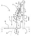
- sharpening equipment in the form of sharpening device is generally indicated by reference numeral 10.
- the device 10 comprises gripping means generally indicated by reference numeral 12, a sharpening means carrier in the form of sharpening element holder as provided by a sharpening element holding base 14 releasably holding a sharpening element in the form of a sharpening stone 16, a guiding layout arranged to perform a sharpening session at a constant sharpening angle in the form of a guiding arm as provided by a guiding rod 18 mounted to reciprocate along an aperture in an adjustably mounted support guide 20 in parallel with the sharpening surface 16.1 of the sharpening stone 16 in response to retaining equal corresponding inner angles 22, and an angle adjustment facility in the form of a swivelling mechanism forming the connection between the rod 18 and the gripping means 12 as provided by an connecting arm 24 extending integrally with respect to the gripping means 12 and being swivellably connected to the leading end of the rod 18 via a disc 26 fitted to the rod 18 via a socket 27 with the disc presenting a graduated dial providing face 28 against which the leading end of the arm 24
- the gripping means 12 is provided a jaw fashion assembly 30 comprising an upper jaw 32 extending into the arm 24 and a lower jaw 34.
- An item of which the cutting edge requires sharpening is gripping fashion receivable in the pinching zone 36 defined between the jaws 32, 34.
- Such item is securely so held in response the tightening of a tightenable element 40 engaging screw fashion between the jaws 32, 34.
- an adjustment element 42 situated towards the rear ends of the jaws 32, 34 engages screw fashion with the jaw 32 while urging with its inner end against the inner wall of the jaw 34 as suitably recessed to limit relative adjacent movement of the jaws 32, 34.
- the jaws are retained apart even if not holding an item by means of a spring 44 fitted onto the element 40 between the jaws 32, 34.
- the assembly 30 is arranged to cause its central axis 46 to pass through the pivotal point 48 between the gripping means and the rod 18 in response to the suitable formation of the connecting arm 24. Once an item is thus pinched in the zone 36 the axis 46 passes along its cutting edge.
- a knife 50 is normally held at a relatively small inner angle 22 to result in the one face 50.1 of its leading edge 50.2 lying flush against the sharpening surface 16.1 as its cutting edge bevelling angle is steep. As more clearly shown in figure 2 the knife 50 is pinched in the pinching zone along its blunt edge 50.3. When the cutting edge bevelling angle is not so steep, as shown in the case of scissors 52 in figure 3, the angles 22 require adjustment, as discussed below, to retain the leading edge face 52.1 requiring sharpening in contact with the sharpening surface 16.1.
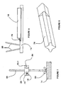
- the gripping means 12 permits adaptation into forming a clamp 54 as shown in figure 4.
- the jaw 32 presents adjacent engaging apertures 56 (as seen in figure 2) engageable by means of wing nuts 58 used for securing a clamp formation 60 to the inner surface of the jaw 32.
- the clamp formation 60 is thus used to clamp an appropriate item, such as a chisel 62, to the gripping means 12 by way of gripping it to the inner surface of the jaw 32.
- its handle 64 extends alongside the disc 26.
- the leading portion of the chisel 62 is still located in the zone which defines the pinching zone in the case of the figures 1 to 3 embodiment the chisel 62 will still lie along an axis 66 that passes through the pivotal point 48.
- desired sharpening depends on the relevant face of the leading edge of a sharpenable item lying flush against the sharpening surface 16.1.
- the guiding layout in conjunction with the swivelling mechanism is thus formed to accommodate an infinite variety of bevels within the range of the device 10.
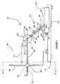
- the device 10 is fitted with a correlator in the form of a linear member as provided by the handle portion 70.1 of the screw 70 which extends in parallel with the sharpening surface 16.1 once the screw 70 is fitted to the guide 20.
- Sharpening is achieved by to-and-fro movement of the sharpenable edge of the appropriate item over the sharpening surface 16.1 in the direction of arrow 72. This is done by manual displacement of the gripping means 12 while urging it to the desired extent against the surface 16.1. It will be appreciated that sharpening is often desired to be carried through by way of uni-directional stroke. To this effect and referring to figure 7 the rod 18 passes with some vertical play along the aperture 74. As lateral movement of a cutting edge over the sharpening surface 16.1 is also often desired the aperture 74 has an oblong horizontal profile thus enabling lateral play of the rod 18 in the aperture 74 as well.
- the base 14 makes provision for filmy holding the stone 16 in position once fitted to thereto by means of a seat 75 into which the stone is locked via a locking plate 77 as secured to the base 14 by means of a wing nut 79.
- the stone 16 is often required to be replaced during a sharpening action to pass though a procedure requiring stones of different grits.
- an object of which an edge is desired to be sharpened is thus secured to the gripping means 12, the desired angle selected on the dial and the support guide 20 locked to the rail 68 in a rod 18 to sharpening surface 16.1 parallel relationship. Sharpening is achieved by desirably sweeping the sharpenable edge over the surface 16.1. Once the one side of the sharpenable edge has been desirably sharpened the gripping means 12 is simply swivelled though 180 degrees owing to the threaded engagement of the rod 18 to the disc 26 and the procedure repeated for the opposite side.
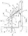
- the device 10 permits the replacement of the disc 26 and the gripping means 12 by a conventional sharpening element 76 for use in conjunction with not-linear edges, as shown in more detail in figure 9. Disengagement is achieved by the leading end of the rod 18 fitting screw fashion into the socket 27 fast with the disc 26.
- the sharpening element 76 is fitted with a socket by means of which it engages screw fashion with the rod 18. To bring the item of which the non-linear edge requires sharpening into a sharpening relationship with the element 76 it is again gripped in the pinching zone 36 of the gripping means 12 as now fitted to the bottom end of the rail 68.
- the rail 68 is thus releasably secured to the base 14 by being screw fashion received in a threaded socket in the base 14 and so locked by means of a wing nut 80.
- An indication of the sharpening angle is achieved by the rail 68 presenting graduated markings 82 that indicate the sharpening angle 84 for as long as the gripping means 12 extends transverse to the rail 68.
- the guide 20 provides a desiredly shaped aperture 84, as shown in figure 7 in a wing 20.1 which has an oblong shape in the direction of the rail 68 while also permitting lateral play to attend to adjacent serrations or the like.
Landscapes
- Engineering & Computer Science (AREA)
- Mechanical Engineering (AREA)
- Finish Polishing, Edge Sharpening, And Grinding By Specific Grinding Devices (AREA)
- Crystals, And After-Treatments Of Crystals (AREA)
- Paper (AREA)
- Magnetic Ceramics (AREA)
- Apparatuses And Processes For Manufacturing Resistors (AREA)
- Facsimile Image Signal Circuits (AREA)
- Image Processing (AREA)
- Picture Signal Circuits (AREA)
Claims (18)
- Schleifvorrichtung (10) zum Schleifen einer schleifbaren Kante eines geeigneten Gegenstands bei einem mindestens im Wesentlichen unveränderten Schleifwinkel, umfassend:Greifmittel (12), das zum festen, aber lösbaren Halten eines derartigen Gegenstands angeordnet ist,ein Schleifelement (76), das eine Schleifoberfläche (16.1) bereitstellt, worin das Schleifelement (76) durch einen Schleifmittelträger (14) in einem Zustand mit nach oben gerichteter Schleifoberfläche fest, aber lösbar gehalten wird und gegen welche Schleifoberfläche (16.1) die schleifbare Kante eines derartigen Gegenstands, der durch das Greifmittel (12) gehalten wird, in einer Über-Kopf-Weise streichend bewegbar ist, wenn die Vorrichtung (10) betriebsbereit verwendet wird,eine Führungsanordnung, die mindestens einen hin- und her- bewegbaren Arm (24) einschließt, der gegen nicht erwünschte Freisetzung entlang einer Trägerführung (20) in einer Weise gleitbar angebracht ist, die eine Hin- und Herbewegung des Arms (24) in einer parallelen Beziehung zu der Schleifoberfläche (16.1) des Schleifelements (76) gestattet, während eine wirksame Schleiftätigkeit zwischen dem Greifmittel (12), das einen derartigen Gegenstand hält, und dem Schleifelement (76) während eines Schleifvorgangs gestattet wird, wobei die Trägerführung (20) bezüglich ihres Abstands über dem Träger (14) an einer Trägergestaltung unendlich, wiederverschließbar, einstellbar angebracht ist, die sich von dem Träger (14) aufwärts erstreckt, wie ersichtlich, wenn die Vorrichtung betriebsbereit positioniert ist, in einer Weise, die die Verwendung des im Wesentlichen vollständigen Umfangs der Schleifoberfläche (16.1) des Schleifelements (76) bis zu einem kleinen Schleifwinkel gestattet, der zwischen der Ebene durch die Kante eines derartigen Gegenstands, der geschliffen werden soll, und seiner Zentralebene definiert ist, undeine Winkeleinstelleinrichtung, die schwenkbar das Greifmittel (12) mit dem Arm (24) verbindet und einen Schleifwinkelanzeiger bereitstellt, der eine Ablesung bezüglich der Größe des Schleifwinkels (84) zeigt, wie folglich zwischen der Schleifoberfläche (16.1) des Schleifelements (76) und der Zentralachse (46) des Greifmittels (12) definiert, der bzw. die gleich zu der Ebene durch die Kante eines derartigen Gegenstandes ist, der geschliffen werden soll und daher korrekt durch das Greifmittel (12) gehalten wird, und wird einmal seine Zentralebene durch das Greifmittel (12) gehalten, wird bei mindestens im Wesentlichen unverändertem Schleifwinkel (84) geschliffen, was erreicht wird, durch Einstellen des Winkelanzeigers auf einen gewünschten Schleifwinkel (84), vor oder nach geeignetem Greifen eines derartigen Gegenstands durch das Greifmittel (12), und Einstellen der Trägerführung (20) auf eine Position entlang der Trägergestaltung, in der der Arm (24) eine Streichaktion ausführen kann, die parallel zu der Schleifoberfläche (16.1) ist, wenn einmal ein Schleifen eines derartigen Gegenstands beginnt, einerseits auf Grund entsprechender innerer Winkel (22) zwischen der Zentralachse (46) des Arms (24) und der Zentralachse des Greifmittels (12) und andererseits der Schleifebene und der Zentralachse des Greifmittels (12), die zueinander gleich erhalten bleiben, worin das Greifmittel (12) ausgebildet ist, dass seine Zentralachse (46), die zentral durch seinen Greifbereich geführt wird, die Schwenkachse der Winkeleinstelleinrichtung transversal schneidet, wodurch ein Schleifen entgegengesetzter, schleifbarer Kanten eines derart angeordneten Gegenstands, die es erfordern bei mindestens im Wesentlichen dem Schleifwinkel (84) geschliffen zu werden, durch Schwenken des Arms (24) um einen Halbkreis mit einem derartigen Gegenstand, ermöglicht wird, der durch das Greifmittel (12) gehalten wird, und Einstellen des Schleifwinkelanzeigers, der so angeordnet ist, eine Anzeige, die sich entlang der Zentralachse (46) des Greifmittels (12) erstreckt, bei dem zuvor verwendeten Winkel bereitzustellen, auf Grund des Anzeigers, welcher die gleiche Graduierungsmaßeinteilung auf beiden Seiten eines Zentralpunkts der Graduierung anzeigt.
- Schleifvorrichtung (10) nach Anspruch 1, worin der hin- und her-bewegbare Arm mit geeignetem Spiel entlang der Trägerführung (20) geführt wird, um mindestens eine Stufe eines Umstellungsvorgangs in einer Ebene, die transversal zu der Schleifoberfläche (16.1) ist, zu gestatten, wodurch der Schleifvorgang anpassungsfähiger gemacht wird, indem ein Anheben des Greifmittels (12), und daher eines Gegenstands, dessen Schleifkante von der Schleifoberfläche (16.1) geschliffen wird, ermöglicht wird, wobei daher ebenso ein unidirektionaler Schleifvorgang ermöglicht wird.
- Schleifvorrichtung (10) nach Anspruch 1 oder Anspruch 2, worin der hin- und her-bewegbare Arm (20) mit seitlichem Spiel entlang der Trägerführung (20) geführt wird, wodurch folglich eine seitliche Bewegung des Arms (24) bezüglich der Schleifoberfläche (16.1) ermöglicht wird, ebenso wie ein kombinierter, Hin- und her- und seitlicher Schleifvorgang ermöglicht wird.
- Schleifvorrichtung (10) nach einem der vorstehenden Ansprüche, die mit einem Schleifstreichrichtungs-Korrelator ausgestattet ist, gegen den eine Bewegung des Arms (24), während der Ausführung eines einen Gegenstand schleifenden Vorgangs bei betriebsbereiter Verwendung der Vorrichtung, durch Fördern seiner parallelen Beziehung mit der Schleifoberfläche (16.1) korrelierbar ist.
- Schleifvorrichtung (10) nach Anspruch 4, worin der Korrelator in der Form eines linearen Elements ist, das sich parallel zu der Schleiffläche des Schleifelements (76) von der Trägerführung (20) und daher in naher benachbarter Beziehung mit dem Arm (24) erstreckt, um seine Verwendung beim Einstellen des Arms in einer parallelen Beziehung zu der Schleiffläche bei der Vorbereitung der Vorrichtung (10) zur Verwendung beim Schleifen der schleifbaren Kante eines Gegenstandes zu fördern.
- Schleifvorrichtung (10) nach einem der vorstehenden Ansprüche, worin der Schleifwinkelanzeiger in der Form einer graduierten Einstellscheibe vorliegt.
- Schleifvorrichtung (10) nach einem der vorstehenden Ansprüche, worin das Greifmittel (12) in der Form einer Klammer (54) vorliegt, um klemmartig einen geeigneten Gegenstand in einem Klemmbereich, der den Greifbereich bereitstellt, zu halten.
- Schleifvorrichtung (10) nach Anspruch 7, worin die Klammer eine backenartige Anordnung (30) bereitstellt, die eine Oberbacke (32) und eine Unterbacke (34) umfasst, die aufeinander schließbar sind, was daher unter anderem das Greifen eines sich längs erstreckenden Gegenstandes ermöglicht, der eine sich längs erstreckende, schleifbare Kante entlang der Kante aufweist, die von der schleifbaren Kante in dem Klemmbereich entfernt ist.
- Schleifvorrichtung (10) nach Anspruch 8, worin die Backen (32, 34) durch ein Schließelement (40) schließbar sind, das schraubenartig zwischen den Backen (32, 34) in Eingriff kommt, während die Greifwirkung der Backen (32, 34) durch ein Einstellelement (42) verstärkt wird, das von den Vorderenden der Backen (32, 34) entfernt angeordnet ist, das schraubenartig mit einer Backe (32) in Eingriff kommt, während es mit seinem inneren Ende gegen die Innenwand der anderen Backe (34) drängt.
- Schleifvorrichtung (10) nach einem der vorstehenden Ansprüche, worin der hin- und her-bewegbare Arm (24) in der Form einer Führungsstange (18) vorliegt, die entlang eines Lochs (74) in der Trägerführung (20) geführt wird.
- Schleifvorrichtung (10) nach einem der vorstehenden Ansprüche, worin die Trägerführung (20) bezüglich ihres Abstands über dem Schleifmittelträger (14) durch eine gleitende, aber verschließbare Anordnung entlang einer linearen Schiene (68), unendlich, wiederverschließbar, einstellbar angebracht ist, welche die Trägergestaltung bereitstellt.
- Schleifvorrichtung (10) nach Anspruch 11, worin sich die Trägergestaltung geeignet erstreckt, um eine Verwendung von dem im Wesentlichen vollständigen Umfang der Schleifoberfläche (16.1) des Schleifelements (76) bis hinunter zu einem kleinen Schleifwinkel zu ermöglichen, die auf Grund dessen, dass sie sich senkrecht erstreckt und von dem vorderen Ende der Schleifoberfläche (16.1) geeigneterweise rückwärtig angeordnet ist, damit die schleifbare Kante eines Gegenstandes, der geschliffen werden soll und einmal durch das Greifmittel (12) gehalten ist, an dem vorderen Ende der Schleifoberfläche (16.1), sogar bei einem kleinen Schleifwinkel, positionierbar ist.
- Schleifvorrichtung (10) nach Anspruch 12, worin die Trägergestaltung in der Form einer Schiene (68) vorliegt, die sich im Allgemeinen S-förmig erstreckt während sie einen kurzen Träger bereitstellt, der mit einem Schienenabschnitt in Eingriff kommt, der an der oberen Oberfläche des Trägers befestigt ist und sich durch eine Krümmung in eine Schienenabschnittsanordnung erstreckt, die sich rückwärts von dem vorderen Ende der Schleifoberfläche (16.1) erstreckt, die sich wiederum durch eine Krümmung in einen aufrechten Schienenabschnitt erstreckt, der die wirksame Länge der Schiene (68) bereitstellt, entlang welcher die Trägerführung (20) versetzbar angebracht ist, worin die Schienenabschnittsanordnung von geeigneter Länge ist, das Ziel einer Verwendung von dem im Wesentlichen vollständigen Umfang der Schleifoberfläche (16.1) des Schleifelements (76) bis hinunter zu einem kleinen Schleifwinkel zu erreichen.
- Schleifvorrichtung nach Anspruch 13, worin die Schiene (68) schwenkbar an dem Träger (14) angebracht ist, der das Schwenken seines Trägerführungshalteabschnitts in eine benachbarte Beziehung bezüglich der Schleifoberfläche (16.1) ermöglicht, um dadurch die Kante eines Gegenstandes, der geschliffen werden soll, und der länger als die Breite des Schleifelements (76) ist, zu schleifen, ohne das Halten eines derartigen Gegenstands durch das Greifmittel (12) in Reaktion auf erwünschtes Schwenken und Wiederverschließen der Schiene (68) an den Träger, wieder einstellen zu müssen.
- Schleifvorrichtung (10) nach einem der vorstehenden Ansprüche, worin die Winkeleinstellungseinrichtung an dem vorderen Ende des hin- und her- bewegbaren Arms (24) angebracht ist.
- Schleifvorrichtung (10) nach Anspruch 15, die ebenso zum Schleifen einer gezahnten oder anderen ähnlichen, nicht-linearen schleifbaren Kante bereitgestellt ist, die durch einen geeigneten Gegenstand bereitgestellt ist, dadurch dass der einstellbare Schwenkmechanismus durch ein Schleifelement mit gewöhnlich gezahnter Kante oder dergleichen (76) ausgetauscht werden kann, der daher lösbar an dem vorderen Ende des hinund her- bewegbaren Arms (24) angeordnet ist und sich so in das Greifmittel (12) erstreckt, während ein festes Halten eines derartigen Gegenstandes durch das Greifmittel (12) bereitgestellt wird, worin das Letztere an dem Ende der Trägergestaltung angebracht ist durch das es herkömmlich an dem Träger angebracht ist und daher so via Schwenkmechanismus lösbar angebracht ist, der von dem Arm (24) freigesetzt wird, worin die Trägerführung (20) ebenso ein Loch (74) bereitstellt, so dass der Arm (24) geeignetes Spiel erhält, um eine Hin- und Herbewegung bei einer geeigneten Neigung auszuführen, um die Kante eines derartigen Gegenstandes, der geeignet durch das Greifmittel (12) gehalten wird, zu schleifen.
- Schleifvorrichtung (10) nach Anspruch 16, worin die Trägergestaltung eine Schleifwinkelgraduierung dort entlang bereitstellt, die anzeigt, den Schleifwinkel (84) zwischen dem Arm (24), der ein gezahntes Kantenschleifelement oder dergleichen (76) trägt, und einem entsprechend gekanteten Gegenstand, der durch das Greifmittel (12) in einer Weise gehalten wird, die bewirkt, dass sich ein derartiger Gegenstand zu der Trägergestaltung transversal erstreckt.
- Schleifvorrichtungssatz, der zu einer Schleifvorrichtung (10) nach Anspruch 1 zusammensetzbar ist, worin der Satz umfasst
Greifmittel (12) zum festen, aber lösbaren Halten eines Gegenstandes, der eine schleifbare Kante aufweist;
ein Schleifelement (76), das eine Schleifoberfläche (16.1) aufweist;
einen Schleifelementträger (14) zum festen, aber lösbaren Halten des Schleifelements (76) in einem Zustand mit nach oben gerichteter Schleifoberfläche (16.1);
eine Trägerführung (20),
eine Führungsanordnung, die einen mindestens hin- und her-bewegbaren Arm (24) einschließt, der gegen unerwünschte Freigabe entlang der Trägerführung (20) gleitbar angebracht ist;
eine an dem Träger (14) befestigbare Trägergestaltung;
worin die Trägerführung (20) bezüglich ihres Abstands über dem Träger an der Trägergestaltung unendlich, wiederverschließbar, einstellbar angebracht ist; und
eine Winkeleinstelleinrichtung zum schwenkbaren Verbinden des Greifmittels (12) mit dem Arm (24), wobei zumindest wenn der Satz einmal zusammengesetzt ist, die Winkeleinstelleinrichtung eine Schleifwinkelanzeige aufweist, die eine Ablesung bezüglich der Größe des Schleifwinkels (84) zeigt.
Applications Claiming Priority (5)
| Application Number | Priority Date | Filing Date | Title |
|---|---|---|---|
| ZA9803774 | 1998-05-05 | ||
| ZA983774 | 1998-05-05 | ||
| ZA9811222 | 1998-12-08 | ||
| ZA9811222 | 1998-12-08 | ||
| PCT/ZA1999/000031 WO1999056915A1 (en) | 1998-05-05 | 1999-05-05 | Sharpenable edge sharpening equipment |
Publications (2)
| Publication Number | Publication Date |
|---|---|
| EP1075356A1 EP1075356A1 (de) | 2001-02-14 |
| EP1075356B1 true EP1075356B1 (de) | 2004-08-11 |
Family
ID=27144666
Family Applications (1)
| Application Number | Title | Priority Date | Filing Date |
|---|---|---|---|
| EP99924554A Expired - Lifetime EP1075356B1 (de) | 1998-05-05 | 1999-05-05 | Schärfvorrichtung für schärfbare kanten |
Country Status (6)
| Country | Link |
|---|---|
| EP (1) | EP1075356B1 (de) |
| AT (1) | ATE273107T1 (de) |
| AU (1) | AU4102999A (de) |
| CA (1) | CA2331369A1 (de) |
| DE (1) | DE69919345T2 (de) |
| WO (1) | WO1999056915A1 (de) |
Families Citing this family (14)
| Publication number | Priority date | Publication date | Assignee | Title |
|---|---|---|---|---|
| SE524407C2 (sv) * | 2002-10-23 | 2004-08-03 | Thomas Loefvenmark | Anordning för bryning |
| CN1835818A (zh) * | 2003-08-13 | 2006-09-20 | 埃奇克拉夫特公司 | 通用型手动剪刀刃磨器 |
| US11052512B1 (en) | 2013-05-08 | 2021-07-06 | Clay A. Allison | Adjustable knife sharpener and clamping assembly |
| US10744614B1 (en) | 2013-05-08 | 2020-08-18 | Clay A. Allison | Adjustable sharpening apparatus and method for cutting implements |
| US9216488B2 (en) * | 2013-05-08 | 2015-12-22 | Clay A. Allison | Adjustable sharpening apparatus and method for cutting implements |
| EP2883655B1 (de) * | 2013-12-12 | 2017-01-04 | Tormek AB | Einspannmittel für eine Schleifmaschine und Schleifmaschine mit den Einspannmitteln |
| US9221144B2 (en) | 2013-12-23 | 2015-12-29 | David G. Powell | Universal sharpening jig for a cutting blade |
| SE538902C2 (sv) * | 2015-06-01 | 2017-01-31 | Tormek Ab | A jig device for a grinding machine and a grinding machine comprising the jig device |
| DE102015118430B4 (de) * | 2015-10-28 | 2017-08-31 | Ralf Wilde | Schleifvorrichtung zum Schleifen einer Klinge |
| CN110091264B (zh) * | 2019-03-27 | 2020-11-20 | 义乌市安航科技有限公司 | 一种雕刻刀磨刀器 |
| WO2022038594A1 (en) * | 2020-08-19 | 2022-02-24 | Alex Gontmakher | A blade sharpening system |
| US11897076B2 (en) | 2021-04-20 | 2024-02-13 | Clay A. Allison | Knife sharpener with clamping assembly |
| US12350783B2 (en) | 2022-06-10 | 2025-07-08 | Clay A. Allison | Clamping assembly for a blade sharpener |
| EP4648922A1 (de) * | 2023-01-11 | 2025-11-19 | Darex, Llc | Modularer schärfer für kantwerkzeuge |
Family Cites Families (6)
| Publication number | Priority date | Publication date | Assignee | Title |
|---|---|---|---|---|
| US1371947A (en) * | 1919-12-15 | 1921-03-15 | Stratton Ezra Millard | Shears-grinder |
| US1422635A (en) * | 1920-12-27 | 1922-07-11 | Arthur O S Taylor | Grinding mechanism |
| US1738936A (en) * | 1926-04-26 | 1929-12-10 | Strnad James Edward | Scissors-sharpening device |
| US2165929A (en) * | 1937-04-09 | 1939-07-11 | John A Lentz | Instrument sharpener |
| US2370908A (en) * | 1944-04-03 | 1945-03-06 | Llorens Jose Amaury | Oilstoning device for plane irons and chisel blades |
| US4759153A (en) * | 1986-07-14 | 1988-07-26 | Morton Cohen | Method and apparatus for sharpening a serrated cutting edge |
-
1999
- 1999-05-05 EP EP99924554A patent/EP1075356B1/de not_active Expired - Lifetime
- 1999-05-05 CA CA002331369A patent/CA2331369A1/en not_active Abandoned
- 1999-05-05 WO PCT/ZA1999/000031 patent/WO1999056915A1/en not_active Ceased
- 1999-05-05 AT AT99924554T patent/ATE273107T1/de not_active IP Right Cessation
- 1999-05-05 AU AU41029/99A patent/AU4102999A/en not_active Abandoned
- 1999-05-05 DE DE69919345T patent/DE69919345T2/de not_active Expired - Lifetime
Also Published As
| Publication number | Publication date |
|---|---|
| AU4102999A (en) | 1999-11-23 |
| ATE273107T1 (de) | 2004-08-15 |
| CA2331369A1 (en) | 1999-11-11 |
| WO1999056915A1 (en) | 1999-11-11 |
| DE69919345D1 (de) | 2004-09-16 |
| DE69919345T2 (de) | 2005-09-08 |
| EP1075356A1 (de) | 2001-02-14 |
Similar Documents
| Publication | Publication Date | Title |
|---|---|---|
| US5195275A (en) | Blade sharpener | |
| EP1075356B1 (de) | Schärfvorrichtung für schärfbare kanten | |
| USRE43884E1 (en) | Apparatus for precision steeling/conditioning of knife edges | |
| US4441279A (en) | Portable sharpener | |
| US5582542A (en) | Apparatus and method for sharpening a cutting tool | |
| US4731953A (en) | Knife sharpener | |
| US7549910B2 (en) | Blade sharpening holder | |
| US4216627A (en) | Shear sharpener | |
| US20100323597A1 (en) | Apparatus for precision steeling/conditioning of knife edges | |
| US9168640B2 (en) | Holder for sharpening and faceting | |
| US7967666B1 (en) | Blade sharpener | |
| US4912881A (en) | Multiple angle dressing device for tools and stock | |
| US5431070A (en) | Adjustable knife blade guide | |
| US5462476A (en) | Blade sharpening device | |
| US7335093B1 (en) | Blade sharpening holder | |
| CA2228943A1 (en) | Apparatus for sharpening/bevelling of ski or snowboard edges | |
| US5142946A (en) | Sharpener for circular saws | |
| EP0225806A2 (de) | Werkzeughalterung | |
| ZA200007052B (en) | Sharpenable edge sharpening equipment. | |
| EP1748868B1 (de) | Vorrichtung für das präzisionsverstählen/konditionieren von messerschneiden | |
| US20110053480A1 (en) | Scraper and sharpening tool combination and sharpening method | |
| AU638677B2 (en) | Blade sharpener | |
| AU2021101203B4 (en) | Blade sharpener device | |
| US1386341A (en) | File-holder | |
| CA2619791C (en) | Blade sharpening holder |
Legal Events
| Date | Code | Title | Description |
|---|---|---|---|
| PUAI | Public reference made under article 153(3) epc to a published international application that has entered the european phase |
Free format text: ORIGINAL CODE: 0009012 |
|
| 17P | Request for examination filed |
Effective date: 20001120 |
|
| AK | Designated contracting states |
Kind code of ref document: A1 Designated state(s): AT DE ES FR GB IT |
|
| 17Q | First examination report despatched |
Effective date: 20020114 |
|
| GRAP | Despatch of communication of intention to grant a patent |
Free format text: ORIGINAL CODE: EPIDOSNIGR1 |
|
| GRAS | Grant fee paid |
Free format text: ORIGINAL CODE: EPIDOSNIGR3 |
|
| GRAA | (expected) grant |
Free format text: ORIGINAL CODE: 0009210 |
|
| AK | Designated contracting states |
Kind code of ref document: B1 Designated state(s): AT DE ES FR GB IT |
|
| PG25 | Lapsed in a contracting state [announced via postgrant information from national office to epo] |
Ref country code: IT Free format text: LAPSE BECAUSE OF FAILURE TO SUBMIT A TRANSLATION OF THE DESCRIPTION OR TO PAY THE FEE WITHIN THE PRESCRIBED TIME-LIMIT;WARNING: LAPSES OF ITALIAN PATENTS WITH EFFECTIVE DATE BEFORE 2007 MAY HAVE OCCURRED AT ANY TIME BEFORE 2007. THE CORRECT EFFECTIVE DATE MAY BE DIFFERENT FROM THE ONE RECORDED. Effective date: 20040811 Ref country code: FR Free format text: LAPSE BECAUSE OF FAILURE TO SUBMIT A TRANSLATION OF THE DESCRIPTION OR TO PAY THE FEE WITHIN THE PRESCRIBED TIME-LIMIT Effective date: 20040811 |
|
| REG | Reference to a national code |
Ref country code: GB Ref legal event code: FG4D |
|
| REF | Corresponds to: |
Ref document number: 69919345 Country of ref document: DE Date of ref document: 20040916 Kind code of ref document: P |
|
| PG25 | Lapsed in a contracting state [announced via postgrant information from national office to epo] |
Ref country code: ES Free format text: LAPSE BECAUSE OF FAILURE TO SUBMIT A TRANSLATION OF THE DESCRIPTION OR TO PAY THE FEE WITHIN THE PRESCRIBED TIME-LIMIT Effective date: 20041122 |
|
| PGFP | Annual fee paid to national office [announced via postgrant information from national office to epo] |
Ref country code: AT Payment date: 20050523 Year of fee payment: 7 |
|
| PLBE | No opposition filed within time limit |
Free format text: ORIGINAL CODE: 0009261 |
|
| STAA | Information on the status of an ep patent application or granted ep patent |
Free format text: STATUS: NO OPPOSITION FILED WITHIN TIME LIMIT |
|
| 26N | No opposition filed |
Effective date: 20050512 |
|
| EN | Fr: translation not filed | ||
| EN | Fr: translation not filed | ||
| PG25 | Lapsed in a contracting state [announced via postgrant information from national office to epo] |
Ref country code: AT Free format text: LAPSE BECAUSE OF NON-PAYMENT OF DUE FEES Effective date: 20060505 |
|
| PGFP | Annual fee paid to national office [announced via postgrant information from national office to epo] |
Ref country code: GB Payment date: 20070618 Year of fee payment: 9 |
|
| GBPC | Gb: european patent ceased through non-payment of renewal fee |
Effective date: 20080505 |
|
| PG25 | Lapsed in a contracting state [announced via postgrant information from national office to epo] |
Ref country code: GB Free format text: LAPSE BECAUSE OF NON-PAYMENT OF DUE FEES Effective date: 20080505 |
|
| PGFP | Annual fee paid to national office [announced via postgrant information from national office to epo] |
Ref country code: DE Payment date: 20140530 Year of fee payment: 16 |
|
| REG | Reference to a national code |
Ref country code: DE Ref legal event code: R119 Ref document number: 69919345 Country of ref document: DE |
|
| PG25 | Lapsed in a contracting state [announced via postgrant information from national office to epo] |
Ref country code: DE Free format text: LAPSE BECAUSE OF NON-PAYMENT OF DUE FEES Effective date: 20151201 |