EP1076603B1 - Verfahren zum verarbeiten einer metallschmelze, insbesondere einer leichtmetallschemelze, sowie gekapselter und mit schutzgas beaufschlagbarer dosierofen - Google Patents
Verfahren zum verarbeiten einer metallschmelze, insbesondere einer leichtmetallschemelze, sowie gekapselter und mit schutzgas beaufschlagbarer dosierofen Download PDFInfo
- Publication number
- EP1076603B1 EP1076603B1 EP99927667A EP99927667A EP1076603B1 EP 1076603 B1 EP1076603 B1 EP 1076603B1 EP 99927667 A EP99927667 A EP 99927667A EP 99927667 A EP99927667 A EP 99927667A EP 1076603 B1 EP1076603 B1 EP 1076603B1
- Authority
- EP
- European Patent Office
- Prior art keywords
- furnace
- molten metal
- casting
- metering
- level
- Prior art date
- Legal status (The legal status is an assumption and is not a legal conclusion. Google has not performed a legal analysis and makes no representation as to the accuracy of the status listed.)
- Expired - Lifetime
Links
Images



Classifications
-
- B—PERFORMING OPERATIONS; TRANSPORTING
- B22—CASTING; POWDER METALLURGY
- B22D—CASTING OF METALS; CASTING OF OTHER SUBSTANCES BY THE SAME PROCESSES OR DEVICES
- B22D17/00—Pressure die casting or injection die casting, i.e. casting in which the metal is forced into a mould under high pressure
- B22D17/20—Accessories: Details
- B22D17/30—Accessories for supplying molten metal, e.g. in rations
-
- B—PERFORMING OPERATIONS; TRANSPORTING
- B22—CASTING; POWDER METALLURGY
- B22D—CASTING OF METALS; CASTING OF OTHER SUBSTANCES BY THE SAME PROCESSES OR DEVICES
- B22D17/00—Pressure die casting or injection die casting, i.e. casting in which the metal is forced into a mould under high pressure
- B22D17/20—Accessories: Details
- B22D17/28—Melting pots
Definitions
- the invention relates to a method for processing a molten metal, in particular one Light metal melt, by means of an encapsulated dosing furnace, which is charged with protective gas, the is connected via a riser pipe to a casting machine or mold, which has a quantifiable Quantity of melt is charged by pressurizing the protective gas in the dosing furnace and a metering oven suitable for carrying out the method.
- the melt level by means of a pressure-controlled inert gas filling is kept constant during the melting and casting phase.
- DE-OS 42 03 193 is a method for handling magnesium and magnesium alloy melts known in which the melt of a casting device to be charged by generating an overpressure in a protective gas volume above the molten bath level is fed.
- the overpressure is generated by opening a valve that the dosing furnace with connects a pressure accumulator.
- the melt is metered by measuring the weight the supplied melt or a size dependent thereon. After dosing A pressure equalization between the protective gas in the dosing furnace and the pouring device brought about, that is to say that atmospheric pressure is established when the casting is removed.
- the solution has the disadvantage that the metering of the amount of melt is also still too imprecise and therefore the quality of the castings is insufficient.
- DEA-4403285 discloses a dosing oven with a tightly fitting lid which a connecting pipe for protective gas, pouring pipe, measuring tube, metering tube and one Charging device are connected.
- a disadvantage of this known metering furnace is that Regulation of the protective gas pressure does not reliably indicate the bath level and that the Dosing accuracy is not guaranteed.
- the invention is based on the object, the method of the type mentioned to improve that a metallurgically safe process control, an accurate and fast Dosing of the amount of melt required for the casting process and an optimal coupling to the downstream casting process takes place and enables casting with high quality of the casting becomes.
- a dosing furnace suitable for the process should be specified.
- the object is achieved by that the amount of melt corresponding to a gross cast is fed to the coupled casting machine or mold by increasing the gas pressure in the metering furnace, the increase in the gas pressure corresponding to the height difference between the bath level of the melt and a desired level in the casting machine or mold, that the temperature of the melt is measured in the metering furnace and regulated to a preset temperature value, that the melt level in the riser pipe and / or the bath height of the melt in the metering furnace is measured and regulated between preset limit values and that the gas pressure in the protective gas in the metering furnace is controlled so that the melt level in the riser pipe is essentially the same regardless of the bath height in the metering furnace before each supply of melt to the casting machine or mold, wherein the metered quantity and the casting temperature are kept between selectable limit values by means of the heating powers supplied, the quantity of charging material supplied and the quantity of melt removed as actuating and disturbance variables.
- the method can be carried out so that the gas pressure of the protective gas in the Dosing furnace measured and depending on the bath height of the melt in the dosing furnace a preset function is regulated.
- the invention enables the bathroom mirror by coupling the control loops for the batches the melt in the dosing furnace, the gas pressure in the dosing furnace above the bath surface and the temperature in the melt bath the premature influence of the disturbance variables of the overall process.
- the melt in the riser pipe is expediently heated.
- the heating should be regulated done by measuring the temperature of the melt in the riser pipe and using that on the riser pipe supplied heating power is regulated to a preset temperature value.
- the melt is always transported in the closed system using the shortest paths, the shortest Transport times and under precisely regulated temperature conditions. This makes it manageable Process realized with a high degree of certainty as it is used to produce quality components necessary is.
- the metal addition in the system can be fixed by means of alloy material that is from the supplier has guaranteed properties, or liquid with cleaned and treated melt, the Properties are precisely set and documented.
- the heat is added to the respective phases of the process with constant amounts of metal with minimal paths for heat flow and guarantees optimal energy input and therefore high efficiency.
- the exact quantification is done using a Defined feed control and the metal can with before immersion in the melt With the help of a regulated heating system it can be preheated in a defined manner.
- the melting by immersion into a larger melt pool enables intensive heat transfer at the time where the heat of fusion must be introduced.
- the alloy material is advantageous held in the melt bath first with the help of a guide, so that when entering the Neither metal splashes nor cold material directly into the lower area of the bathroom Melt pool sinks.
- the charging device with guide is preferably in the furnace lid or arranged on the upper side wall so that self-locking prevents Alloy material falls into the furnace uncontrollably.
- liquid charging In the case of liquid charging, a metered amount of metal with a defined temperature is below the Bath surface, for example via a siphon, introduced.
- the liquid batch can be as Supplement can also be used in combination with the fixed batch, for example add cleaned return material.
- the bath level in the system is expediently kept under a protective gas atmosphere at a pressure which is higher than the external atmospheric pressure, as a result of which melting reactions, burn-off losses and contamination are effectively prevented.
- the low dead volume and the quantified recharging enable the protective gas to be used sparingly, so that more expensive gases, such as argon, can also be used. This makes it possible to dispense with environmentally hazardous substances such as SF 6 or SO 2 .
- the level of the bath level in the dosing furnace is reduced due to the constant recharging Area regulated so that the head to the casting machine can be kept low, which one allows relatively low overpressure. This is a simple and precise pressure control realizable.
- the charging material supplied is expediently preheated before being introduced into the metering furnace.
- Controlled heating is expediently again carried out here by the temperature of the charging material and the heating power supplied during preheating is regulated to a preset temperature value.
- the melt is removed during dosing via a riser pipe in the lower area of the bath Low turbulence against gravity, ensuring that none in the upper range of the molten metal that has just been melted is conveyed directly out of the system.
- the method can also be carried out in such a way that it is independent of the casting process Dosing an antechamber to be arranged on the casting machine or mold with the melt is filled.
- the individual control loops can be networked in a programmable controller.
- the coupled control loops of the parameters dosing quantity and casting temperature in connection with post-charging enables a very high dosing accuracy with constant casting temperature.
- the efficiency of the dosing furnace is almost constant due to the energy input Melt volume increased significantly.
- the melt bath is preferably heated in the lower region of the crucible, so that with the help of natural convection currents impermissible overheating, heat build-up and temperature differences in the bathroom can be avoided.
- resistance heating conductors these are used to achieve the required high heating output when melting and keeping warm distributed over the outer surface of the cylindrical dosing furnace or arranged inside in a so-called immersion heater.
- induction heating can be used advantageously, their efficiency by coupling the largely constant melt volume is increased.
- an accurate local power adjustment can be made be made so that, if necessary, also in the lower area of the melt pool the highest performances are achieved.
- the induction technology the possibility of variable frequency selection, the performance and the bath movement targeted adjustment.
- the high melting power of induction enables an ideal compact unit with high flexibility, which, for example, is excellent for use in a flexible manufacturing cell a die-casting foundry.
- the high process reliability enables an increased casting quality as well as an automatic, low-emission and environmentally friendly foundry.
- a metering oven suitable for carrying out the method contains a controller that acts on the device for recharging and is guided either by the level sensor for the bath level of the melt in the furnace or by the signal from the level sensor in the riser pipe in connection with the current furnace pressure and one from the fill level sensor for the bath height of the melt in the furnace or from the signal from the fill level sensor in the riser pipe in connection with the instantaneous furnace pressure, which causes the dosing pressure for the protective gas required for precise dosing.
- the regulator for the gas pressure can be designed so that it with the level sensor bath height of the melt measured in the dosing furnace is activated as a disturbance variable. To this Such a gas pressure is always, regardless of the current level of the bath Dosing furnace maintained that before each supply of melt to the pouring device certain melt level is produced in the riser. Alternatively, the gas pressure can also be adjusted depending on the melt level in the riser, if there is one Height is measured here alone using a level sensor. For the regulation of post-charging the gas pressure in the dosing furnace can then be used.
- the device for recharging with solid charging material expediently consists of one with a hose-shaped sluice and one with the level sensor interacting feed drive for the charging material.
- the device for post-charging with solid charging material can also have a lock a material chamber displaceable by a slide cylinder, at the open ends of which an upper and lower position of the material chamber alternately opening and closing Sliders are attached, and with a feed device controlled by a displacement sensor for the upper position of the material chamber and a gas pressure control device.
- a partial immersion in the melt connected to the lock Support rail provided for the self-locking support of the fixed charging material his.
- the lock with a temperature-controlled heating device for the charging material is preferred equipped.
- a device for post-charging with liquid charging material can expediently be constructed in this way be that it consists of a melt vessel that can be coupled to a filling tube of the dosing furnace exists with a cooperating with the level sensor conveyor for Melt is equipped.
- the riser pipe is also equipped with a temperature-controlled one Heating device equipped for the melt.
- the dosing furnace can consist of a steel crucible as a basic element. For safety reasons this can be surrounded by a melt collecting pan, the free volume of which is in the position is to take up the possibly flowing melt from the dosing furnace.
- induction heating it is also possible to use, for example, a metal crucible with a backfilling ceramic mass, providing good support and additional protection is guaranteed in the case of a crucible leak.
- the riser pipe should have a capacity of at least one gross cast and be practical have an inside diameter of at least 30 mm. It should also go straight from the bottom the filling chamber of the die casting machine or the die. This design guarantees low-turbulence conveying of the melt with a short transport path and ensures so for a short dosing time with low temperature losses.
- the construction of the dosing furnace can be done in this way be designed so that the riser pipe opens into an antechamber, which with a short pipe the filling chamber of the die casting machine is connected.
- the prechamber can have an overflow edge have, so that it only takes up a defined amount of melt.
- the riser pipe with the filling chamber from below one die casting machine is connected and a second, in the amount of the intended Fill level has in the filling chamber connecting channel, via the overdosed Melt is automatically returned to the antechamber.
- a central furnace control e.g. B. in the form of a Programmable logic controller can be provided, with a central control of the Die casting machine for transferring process parameters via a signal line with this central Furnace control is connected.
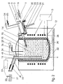
- bolt-shaped alloy material 1 is used with a Via a displacement sensor 2 controlled feed device 3 through a lock seal 4 Sluice 5 pushed.
- the lock 5 is equipped with a heating device 6 for preheating the bolt-shaped alloy material 1 equipped.
- a temperature sensor 7 measures the temperature of the alloy material 1, which is given to a regulator 8 for regulating the heating device 6 becomes.
- a melt bath 10 which is heated with resistance heating elements 11 becomes.
- a temperature sensor 12 in the melt bath 10 gives a measurement signal for the heating power control 13.
- the alloy material 1 is slowly over a support rail 14 in the Melt bath 10 performed, it melts in the upper bath area.
- the bath surface 15 is protected from erosion and oxidation by a protective gas 16.
- the Shielding gas 16 is constantly under a slight excess pressure.
- a level sensor 17 measures the height of the bath surface 15 and triggers when one is exceeded Minimum values from the re-charging of the feed device 3.
- the connection to a casting device takes place through a riser pipe 18.
- the riser pipe 18 is also heated by a heating device 19, which is regulated by means of a thermocouple 20 and a regulator 21 and a sets the desired casting temperature in the melt.
- the dosing furnace is protected with insulation 22 against large radiation losses to the outside. at a leak in the crucible 9, the melt flows into a collecting trough 23 surrounding the crucible 9.
- the gas pressure in the protective gas 16 above the bath surface 15 is measured using a gas pressure sensor 24 measured and controlled with a gas pressure regulator 25 via the gas control valve 26, the Gas pressure regulator 25 connected to the level of the bath surface 15 measured with the fill level sensor 17 is because the gas pressure over the bath surface 15 is influenced by this.
- the gas pressure is now in accordance with the metered quantity and the Head increased to the pouring device, and that as precisely as possible the pressure difference that the height difference between the bath level and a level setpoint in the pouring device equivalent.
- the dosing accuracy can, if necessary, be confirmed by a level sensor be increased in the casting device to the gas pressure regulator 25.
- the pouring device 27 was also filled with protective gas 16, so that the entire dosing and pouring process takes place under protective gas.
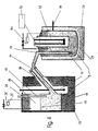
- Figure 2 shows a dosing furnace with inductively heated crucible 9.
- the melt passes through vertical riser pipe 18, heated essentially via the metering furnace, to the interface to the pouring device 27, so that the additional heating device 19 is dimensioned correspondingly smaller can be.
- the level of the melt in the riser 18 is determined by means of a Level sensor 56 measured and regulated via the gas pressure in the metering furnace so that it before each supply of melt to the casting device is approximately the same.
- An induction heater 28 is operated by means of a temperature sensor 12 and the heating power control 13 regulated and a variable frequency and the control of independent coils flexible provision of services.
- the inductive force effect ensures thorough mixing of the melt pool 10 reached, causing segregations and deposits on the ground of the crucible 9 can be safely avoided.
- the crucible 9 is supported with the aid of a ceramic intermediate layer 29, which in addition offers good protection in the event of a crucible leak.
- the alloy material 1, which is in the form of a mass in this case, is heated using a separate heating device 6 preheated to a defined temperature.
- the pigs (possibly several next to each other) are inserted linearly into the lock 30.
- a slide cylinder 31 is in the lower position, so that a slide 32 opens and a slide 33 closes.
- the pressure with the help of a gas pressure regulator 34 and a gas pressure valve 35 for the lock 30 raised to the same level as in the furnace room.
- the slide cylinder 31 moves to the upper position so that the slide 33 is opened.
- the feed device 3 pushes the ingot on the support rail 14 into the melting zone on the bath surface 15th
- the entire lock 30 can be decoupled from a mounting flange, so that ingots can be introduced into the unpressurized furnace very quickly.
- the geometry the lock 30 is designed so that hot protective gas 16 remains trapped in the upper part and only a small amount of air is brought in from outside when the pigs are inserted.
- control of the process parameters and the dosing are carried out in a similar manner to that of the Embodiment according to FIG. 1.
- FIG. 3 shows the coupling of the control loops for the temperature T m , T fl of the alloy material 1, the melt temperature T S , the casting temperature T g , the bath height H and the gas pressure P g of the protective gas 16 for the embodiment according to FIG. 1.
- the transition functions are generally marked with F.
- the strongly changing melt temperature T S which causes a different expansion of the melt bath 10, acts as a disturbance variable on the bath height H.
- the melt temperature T S is therefore regulated within narrow limits by means of the heating power controller 13.
- the bath height H influences the gas pressure P g of the protective gas 16 in the furnace chamber. This is measured with the gas pressure sensor 24 and controlled via the gas control valve 26 and the gas pressure regulator 25, a disturbance variable being applied in such a way that the melt level in the riser pipe 18 is the same regardless of the bath height H of the melt bath 10 in the crucible 9 before each metering process.
- the gas pressure P g is then temporarily increased in accordance with the required delivery head to the pouring device 27 and the metering quantity md.
- the dosing accuracy can be confirmed by feedback of the dosed amount of melt to the gas pressure regulator 25 can be increased.
- melt temperature T S acts as a disturbance variable on the gas pressure P g in the furnace chamber, so that the smallest possible fluctuations in the melt temperature T S are desired.
- the casting temperature T g can be measured before or after the interface to the casting device 27 and is set precisely by the controller 8 of the heating device 19, the input variable being the melt temperature T S in the melt bath 10. This results in the melt bath 10 as a complex function F from the thermal energy introduced, depending on the regulated heating power of the temperature T m or T fl of the alloy material 1 and the charging quantities m or fl used.
- the temperature T m of the solid alloy material 1 is set with the heating regulated by the controller 8 in the preheating process, starting from the ambient temperature T mo .
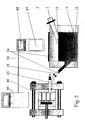
- FIG 4 shows a side section of a transport vessel 37, from which the melt bath 10 below the Bath surface 15 is re-changed with a melt quantum via a filler pipe 38 can be.
- a delivery channel 39 is removed from the transport vessel 37 by a detachable one Coupling 40 is tightly connected to the filler pipe 38.
- the delivery pressure regulator 41 can be recharged in liquid until the fill level sensor 17 in the melt bath 10 of the dosing furnace switches off at maximum bath height H.
- the transport vessel 37 can be kept at a defined temperature T fl with a resistance-heated immersion heater 42 with the aid of a heating control 43 and a thermocouple 44.
- Fig. 5 shows an example of the interaction of the dosing furnace with a downstream one Molding apparatus.
- a specific one is Amount of magnesium melted.
- the crucible 9 is on the riser 18, which is in the lower Area of the melt pool 10 starts with the filling chamber 45 of a die casting machine connected to which a die 40 connects.
- the space above the melt bath 10 is filled with argon, which is removed from a storage vessel 47 becomes.
- the filling chamber 45 and the die 40 are also filled with argon.
- the melt is then conveyed through the piston into the die 46 and the argon displaced from the die 46, the filling chamber 45 immediately after the shot is filled again with argon so that the bath level in the riser pipe 18 does not come into contact with air comes. After the casting has been removed from the die 46, it is again filled with argon.
- All control processes are carried out by a central furnace control 48, which for Transfer of process parameters also via a signal line 50 with a central controller 49 of the die casting machine is connected.
- the central furnace controller 48 which is implemented by a programmable logic controller controls the timing of all processes very flexibly, e.g. B. by programmed "if - then" conditions, so that in the set-up phase, when casting weight, Solidification times, mold closing times, charging times, ingot formats, dosing times, required Delivery amount etc. are fixed, individual coordination of the individual control loops is made can be.
- FIG. 6 shows a variant of the coupling between the die casting machine and the riser pipe 18.
- a prechamber 51 which is connected via a connecting channel 53 is connected to the filling chamber 45.
- the connection channel opens 53 so into the filling chamber 45 that too much dosed melt automatically into the pre-chamber 51st flows back after the piston of the die casting machine the mouth of the riser pipe 18th has run over, at which moment the gas pressure in the metering furnace is reduced becomes.
- the mouth of the connecting channel 53 in the filling chamber 45 must therefore at one point be placed at which the fill level corresponds as exactly as possible to the dosage of a shot.
- the riser pipe 18 has a heated, self-contained prechamber 51 an overflow edge 54 connected.
- the volume of the pre-chamber 51 corresponds in this case exactly one shot.
- a tube extending from the filling chamber 45 of the die casting machine 52 plunges into the pre-chamber 51.
- the coupling to the filling chamber 45 is thus somewhat flexible.
- the filling chamber 45 is filled by generating a pressure difference between the Pre-chamber 51 and the filling chamber 45 via a protective gas line 55 after the gas pressure was taken back in the dosing oven.
Landscapes
- Engineering & Computer Science (AREA)
- Mechanical Engineering (AREA)
- Casting Support Devices, Ladles, And Melt Control Thereby (AREA)
- Manufacture And Refinement Of Metals (AREA)
- Waste-Gas Treatment And Other Accessory Devices For Furnaces (AREA)
Description
daß die einem Bruttoabguß entsprechende Schmelzemenge der angekoppelten Gießmaschine oder -form mittels Erhöhung des Gasdrucks im Dosierofen zugeführt wird, wobei die Erhöhung des Gasdrucks der Höhendifferenz zwischen dem Badspiegel der Schmelze und einem Füllstand-sollwert in der Gießmaschine oder-form entspricht,
daß im Dosierofen die Temperatur der Schmelze gemessen und auf einen voreingestellten Temperaturwert geregelt wird,
daß der Schmelzestand im Steigrohr und/oder die Badhöhe der Schmelze im Dosierofen gemessen und zwischen voreingestellten Grenzwerten geregelt wird und
daß der Gasdruck im Schutzgas im Dosierofen so geregelt wird, daß der Schmelzestand im Steigrohr unabhängig von der Badhöhe im Dosierofen vor jedem Zuführen von Schmelze zur Gießmaschine oder -form im wesentlichen gleich ist,
wobei die Dosiermenge und die Gießtemperatur mittels der zugeführten Heizleistungen, der Menge des zugeführten Chargiermaterials und der entnommenen Schmelzemenge als Stell- und Störgrößen zwischen wählbaren Grenzwerten gehalten werden.
einen Regler, der auf die Einrichtung zu Nachchargierung einwirkt und geführt wird entweder von dem Füllstandssensor für die Badhöhe der Schmelze im Ofen oder von dem Signal des Füllstandssensors im Steigrohr in Verbindung mit dem momentanen Ofendruck und
einen von dem Füllstandssensor für die Badhöhe der Schmelze im Ofen oder von dem Signal des Füllstandssensors im Steigrohr in Verbindung mit dem momentanen Ofendruck geführten Regler, der den für eine genaue Dosierung erforderlichen Dosierdruck für das Schutzgas bewirkt.
- Fig. 1
- einen Schnitt durch einen Dosierofen mit Nachchargierung in Form von Bolzen,
- Fig. 2
- einen Schnitt durch einen Dosierofen mit induktiv beheiztem Tiegel,
- Fig. 3
- die miteinander gekoppelten Regelkreise für die Temperaturen, Badhöhe und Gasdruck für einen Dosierofen gemäß Fig. 1,
- Fig. 4
- einen Schnitt durch einen Dosierofen und ein Transportgefäß für flüssige Nachchargierung,
- Fig. 5
- eine schematische Darstellung des Dosierofens zusammen mit einer nachgeordneten Gießmaschine,
- Fig. 6
- eine Variante der Kopplung von Dosierofen und Füllkammer einer Druckgießmaschine und
- Fig. 7
- eine zweite Variante der Kopplung von Dosierofen und Füllkammer einer Druckgießmaschine
Claims (33)
- Verfahren zum Verarbeiten einer Metallschmelze, insbesondere einer Leichtmetallschmelze, mittels eines gekapselten, mit Schutzgas beaufschlagten Dosierofens, in dem die Badhöhe gemessen und von dem aus die Gießmaschine oder -form mit einer quantifizierbaren Schmelzemenge mittels Druckbeaufschlagung des Schutzgases im Dosierofen beschickt wird, wobei der Gießprozess unter Schutzgas erfolgt,
dadurch gekennzeichnet, daß die einem Bruttoabguss entsprechende Schmelzemenge einer an den Dosierofen angekoppelten Gießmaschine oder -form mittels Erhöhung des Gasdrucks im Dosierofen zugeführt wird, wobei die Erhöhung des Gasdrucks der Höhendifferenz zwischen dem Badspiegel der Schmelze und einem Füllstandssollwert in der Gießmaschine oder -form entspricht,
daß im Dosierofen die Temperatur der Schmelze gemessen und auf einen voreingestellten Temperaturwert geregelt wird,
daß der Schmelzestand im Steigrohr gemessen und zwischen voreingestellten Grenzwerten geregelt wird und
daß der Schutzgasdruck im Dosierofen so geregelt wird, daß der Schmelzestand im Steigrohr unabhängig von der Badhöhe im Dosierofen vor jedem Zuführen von Schmelze zur Gießmaschine oder -form im wesentlichen gleich ist,
wobei die Dosiermenge und die Gießtemperatur mittels der zugefuhrten Heizleistungen, der Menge des zugeführten Chargiermaterials und der entnommenen Schmelzemenge als Stellund Störgrößen zwischen wählbaren Grenzwerten gehalten werden. - Verfahren nach Anspruch 1, dadurch gekennzeichnet, daß der Gasdruck des Schutzgases im Dosierofen gemessen und in Abhängigkeit von der Badhöhe der Schmelze im Dosierofen nach einer voreingestellten Funktion geregelt wird.
- Verfahren nach Anspruch 1 oder 2, dadurch gekennzeichnet, daß die der Gießmaschine oder -form zugeführte Schmelze im Steigrohr beheizt wird.
- Verfahren nach Anspruch 3, dadurch gekennzeichnet, daß die Temperatur der Schmelze im Steigrohr gemessen und über die am Steigrohr zugeführte Heizleistung auf einen voreingestellten Temperaturwert geregelt wird.
- Verfahren nach einem der vorhergehenden Ansprüche, dadurch gekennzeichnet, daß das zugeführte Chargiermaterial vor dem Einbringen in den Dosierofen vorerwärmt wird.
- Verfahren nach Anspruch 5, dadurch gekennzeichnet, daß die Temperatur des vorerwärmten Chargiermaterials gemessen und über die bei der Vorerwärmung zugeführte Heizleistung auf einen voreingestellten Temperaturwert geregelt wird.
- Verfahren nach einem der vorhergehenden Ansprüche , dadurch gekennzeichnet, daß die Schmelze induktiv beheizt wird.
- Verfahren nach Anspruch 7, dadurch gekennzeichnet, daß die Heizleistung frequenzgeregelt wird.
- Verfahren nach einem der vorhergehenden Ansprüche , dadurch gekennzeichnet, daß der Badspiegel der Schmelze bei Chargierung mit festem Legierungsmaterial zwischen einem Maximalwert und einem Minimalwert so geregelt wird, daß das Schmelzevolumen höchstens um ca. 2% schwankt.
- Verfahren nach einem der Ansprüche 1 bis 8, dadurch gekennzeichnet, daß der Badspiegel der Schmelze bei Chargierung mit flüssigem Legierungsmaterial zwischen einem Maximalwert und Minimalwert so geregelt wird, daß das Schmelzevolumen höchstens um 50% schwankt.
- Verfahren nach einem der vorhergehenden Ansprüche, dadurch gekennzeichnet, daß der Gasdruck im Dosierofen ständig über dem äußeren Atmosphärendruck gehalten wird.
- Verfahren nach einem der vorhergehenden Ansprüche, dadurch gekennzeichnet, daß festes Legierungsmaterial bei der Chargierung im oberen Bereich der Schmelze festgehalten wird.
- Verfahren nach einem der vorhergehenden Ansprüche, dadurch gekennzeichnet, daß die Schmelze stets entgegen der Schwerkraft gefördert wird.
- Verfahren nach einem der vorhergehenden Ansprüche, dadurch gekennzeichnet, daß zum zeitlich vom Gießprozess unabhängigen Dosieren eine an der Gießmaschine oder -form anzuordnende Vorkammer mit der Schmelze gefüllt wird.
- Verfahren nach einem der vorhergehenden Ansprüche, dadurch gekennzeichnet, daß als Schutzgas Argon verwendet wird.
- Verfahren nach einem der vorhergehenden Ansprüche, dadurch gekennzeichnet, daß die einzelnen Regelkreise in einer programmierbaren Steuerung vernetzt werden.
- Gekapselter und mit Schutzgas beaufschlagter, mit einem Füllstandssensor (17) für die Badhöhe (H) der Schmelze ausgerüsteter Dosierofen, der eine Einrichtung (1) zur Nachchargierung mit festem oder flüssigem Chargiermaterial aufweist, über ein Steigrohr (18) mit einer Gießmaschine oder -form (27) verbindbar und mit einer Heizeinrichtung (11, 28) versehen ist, zur Durchführung des Verfahrens nach einem der vorhergehenden Ansprüche
gekennzeichnet durch
einen Regler (13), der auf die Einrichtung zur Nachchargierung einwirkt und geführt wird entweder von dem Füllstandssensor (17) für die Badhöhe der Schmelze im Ofen oder von dem Signal des Füllstandssensors (56) im Steigrohr in Verbindung mit dem momentanen Ofendruck und
einen von dem Füllstandssensor (17) für die Badhöhe der Schmelze im Ofen oder von dem Signal des Füllstandssensors (56) im Steigrohr in Verbindung mit dem momentanen Ofendruck geführten Regler (25), der den für eine genaue Dosierung erforderlichen Dosierdruck für das Schutzgas (16) bewirkt. - Dosierofen nach Anspruch 17, dadurch gekennzeichnet, daß dem Regler (25) die mit dem Füllstandsensor (17) gemessene Badhöhe (H) der Schmelze als Störgröße angeschaltet ist.
- Dosierofen nach Anspruch 17 oder 18, dadurch gekennzeichnet, daß die Einrichtung zur Nachchargierung mit festem Chargiermaterial (1) eine mit einer schlauchförmigen Dichtung (4) versehenen Schleuse (5) und einen mit dem Füllstandsensor (17) zusammenwirkenden Vorschubantrieb (3) für das Chargiermaterial (1) aufweist.
- Dosierofen nach Anspruch 17 oder 18, dadurch gekennzeichnet, daß die Einrichtung zur Nachchargierung mit festem Chargiermaterial (1) eine Schleuse (30) mit einer durch einen Schieberzylinder (31) verschiebbaren Materialkammer (36), an deren offenen Enden in einer oberen und unteren Position der Materialkammer (36) wechselweise öffnende und schließende Schieber (32, 33) befestigt sind, und mit einem über einen Wegsensor (2) gesteuerten Vorschubeinrichtung (3) für die obere Position der Materialkammer (36) und eine Gasdruckregeleinrichtung (34, 35) aufweist.
- Dosierofen nach einem der Ansprüche 17 bis 20, dadurch gekennzeichnet, daß er eine teilweise in die Schmelze eintauchende, mit der Schleuse (5, 30) verbundene Auflageschiene (14) für die selbsthemmende Auflage von festem Chargiermaterials (1) aufweist.
- Dosierofen nach einem der Ansprüche 17 bis 21, dadurch gekennzeichnet, daß die Schleuse (5, 30) mit einer temperaturgeregelten Heizeinrichtung (6) für das Chargiermaterial (1) ausgerüstet ist.
- Dosierofen nach Anspruch 17 oder 18, dadurch gekennzeichnet, daß die Einrichtung zur Nachchargierung mit flüssigem Chargiermaterial (1) aus einem an ein Einfüllrohr (38) des Dosierofens ankoppelbaren Schmelzegefäß (37) besteht, das mit einer mit dem Füllstandsensor (17) zusammenwirkenden Fördereinrichtung für die Schmelze ausgerüstet ist.
- Dosierofen nach einem der Ansprüche 17 bis 23, dadurch gekennzeichnet, daß das Steigrohr (18) mit einer temperaturgeregelten Heizeinrichtung (19) für die Schmelze ausgerüstet ist.
- Dosierofen nach einem der Ansprüche 17 bis 24, dadurch gekennzeichnet, daß der Tiegel (9) des Dosierofens aus Stahl besteht.
- Dosierofen nach Anspruch 25, dadurch gekennzeichnet, daß der Stahltiegel (9) in einer Schmelzeauffangwanne (23) angeordnet ist.
- Dosierofen nach einem der Ansprüche 25 oder 26, dadurch gekennzeichnet, daß er induktiv beheizt und der Stahltiegel (9) mit Feuerfestmaterial (29) in die Induktionsheizung (28) eingestampft ist.
- Dosierofen nach einem der Ansprüche 17 bis 27, dadurch gekennzeichnet, daß das Steigrohr (18) ein Fassungsvolumen von mindestens einem Bruttoabguß hat.
- Dosierofen nach einem der Ansprüche 17 bis 28, dadurch gekennzeichnet, daß das Steigrohr (18) direkt von unten mit der Füllkammer (45) einer Druckgießmaschine oder der Druckgießform (46) verbunden ist.
- Dosierofen nach einem der Ansprüche 17 bis 29, dadurch gekennzeichnet, daß das Steigrohr (18) in eine Vorkammer (51) mündet, welche über ein kurzes Rohr (52) mit der Füllkammer (45) der Druckgießmaschine verbunden ist.
- Dosierofen nach Anspruch 30, dadurch gekennzeichnet, daß die Vorkammer (51) eine Überlaufkante (54) aufweist.
- Dosierofen nach einem der Ansprüche 17 bis 31, dadurch gekennzeichnet, daß das Steigrohr (18) von unten mit der Füllkammer (45) einer Druckgießmaschine verbunden ist und einen zweiten, in Höhe der beabsichtigten Füllstandhöhe in die Füllkammer mündenden Verbindungskanal (53) hat.
- Dosierofen nach einem der Ansprüche 17 bis 32 dadurch gekennzeichnet, daß eine zentrale Steuerung (49) der Druckgießmaschine zur Übergabe von Prozessparametern über eine Signalleitung (50) mit einer zentralen Ofensteuerung (48) verbunden ist.
Applications Claiming Priority (5)
| Application Number | Priority Date | Filing Date | Title |
|---|---|---|---|
| DE19818835 | 1998-04-27 | ||
| DE19818835 | 1998-04-27 | ||
| DE19845528A DE19845528A1 (de) | 1998-04-27 | 1998-10-02 | Verfahren zum Verarbeiten einer Metallschmelze, insbesondere einer Leichtmetallschmelze, sowie gekapselter und mit Schutzgas beaufschlagbarer Dosierofen |
| DE19845528 | 1998-10-02 | ||
| PCT/DE1999/001131 WO1999055478A1 (de) | 1998-04-27 | 1999-04-15 | Verfahren zum verarbeiten einer metallschmelze, insbesondere einer leichtmetallschmelze, sowie gekapselter und mit schutzgas beaufschlagbarer dosierofen |
Publications (2)
| Publication Number | Publication Date |
|---|---|
| EP1076603A1 EP1076603A1 (de) | 2001-02-21 |
| EP1076603B1 true EP1076603B1 (de) | 2003-03-05 |
Family
ID=26045797
Family Applications (1)
| Application Number | Title | Priority Date | Filing Date |
|---|---|---|---|
| EP99927667A Expired - Lifetime EP1076603B1 (de) | 1998-04-27 | 1999-04-15 | Verfahren zum verarbeiten einer metallschmelze, insbesondere einer leichtmetallschemelze, sowie gekapselter und mit schutzgas beaufschlagbarer dosierofen |
Country Status (6)
| Country | Link |
|---|---|
| EP (1) | EP1076603B1 (de) |
| JP (1) | JP2002512889A (de) |
| AT (1) | ATE233627T1 (de) |
| AU (1) | AU4496699A (de) |
| DE (1) | DE19980734D2 (de) |
| WO (1) | WO1999055478A1 (de) |
Cited By (1)
| Publication number | Priority date | Publication date | Assignee | Title |
|---|---|---|---|---|
| DE102012108511A1 (de) * | 2012-09-12 | 2014-03-13 | Ks Aluminium-Technologie Gmbh | Dosierofen für eine Druckgussanlage und Verfahren zum Dosieren von Schmelze in eine Gießform mit einem derartigen Dosierofen |
Families Citing this family (8)
| Publication number | Priority date | Publication date | Assignee | Title |
|---|---|---|---|---|
| EP1402977B1 (de) * | 2002-09-25 | 2008-03-19 | Oskar Frech Gmbh & Co. | Schutzgaseinrichtung für Druckgussmaschinen |
| DE102012007363B3 (de) * | 2012-04-12 | 2013-06-20 | Handtmann Leichtmetallgießerei Annaberg GmbH | Vorrichtung zur Steigrohr-Vorwärmung für Dosieröfen |
| CN108788083A (zh) * | 2018-07-27 | 2018-11-13 | 合肥和瑞机械制造有限公司 | 一种汽车配件生产用高精度压铸模具 |
| CN113930738B (zh) * | 2020-06-29 | 2023-09-12 | 宝山钢铁股份有限公司 | 一种真空镀膜用的金属蒸汽调制装置及其调制方法 |
| CN114318200B (zh) * | 2021-12-29 | 2023-08-15 | 北华航天工业学院 | 长材处理装置及基于该装置的热镀生产线和热镀方法 |
| CN115570120A (zh) * | 2022-09-27 | 2023-01-06 | 上海鑫蓝海自动化科技有限公司 | 反重力调压铸造装备安全控制系统及方法 |
| CN115570118A (zh) * | 2022-10-08 | 2023-01-06 | 上海鑫蓝海自动化科技有限公司 | 反重力高温合金调压精铸装备模壳温度补偿装置及方法 |
| CN120286666B (zh) * | 2025-04-17 | 2026-02-27 | 南京航空航天大学 | 一种大直径均匀壁厚高温合金管材控压连铸装置及连铸方法 |
Family Cites Families (6)
| Publication number | Priority date | Publication date | Assignee | Title |
|---|---|---|---|---|
| DE553741C (de) * | 1930-08-29 | 1932-06-30 | Elektronmetall G M B H | Verfahren und Vorrichtung zur stetigen automatischen Beschickung von Schmelzanlagen |
| DE1508560B2 (de) * | 1966-11-21 | 1970-08-06 | Brown, Boveri & Cie Ag, 6800 Mannheim | Verfahren und orrichtung zum Entleeren von Schmelz- oder Warmhalteöfen |
| DE3619525C1 (en) * | 1986-06-10 | 1987-08-06 | Alulahn Giesserei Gmbh & Co Kg | Method and apparatus for the production of castings, for example motor vehicle wheels, from aluminium, magnesium and similar light metals in low-pressure casting machines |
| DE4029386C2 (de) * | 1990-09-12 | 1993-12-16 | Strikfeldt & Koch | Verfahren und Vorrichtung zum Dosieren von Flüssigkeiten, insbesondere von geschmolzenem Metall |
| DE4203193C2 (de) * | 1992-02-05 | 1999-09-30 | Inst Werkstoffkunde Uni Hannov | Verfahren und Vorrichtung zur Handhabung von Magnesium- und Magnesium-Legierungsschmelzen |
| DE4403285A1 (de) * | 1994-01-31 | 1995-08-03 | Alexander Fischer | Dosierofen |
-
1999
- 1999-04-15 AT AT99927667T patent/ATE233627T1/de not_active IP Right Cessation
- 1999-04-15 WO PCT/DE1999/001131 patent/WO1999055478A1/de not_active Ceased
- 1999-04-15 AU AU44966/99A patent/AU4496699A/en not_active Abandoned
- 1999-04-15 DE DE19980734T patent/DE19980734D2/de not_active Ceased
- 1999-04-15 JP JP2000545662A patent/JP2002512889A/ja active Pending
- 1999-04-15 EP EP99927667A patent/EP1076603B1/de not_active Expired - Lifetime
Cited By (1)
| Publication number | Priority date | Publication date | Assignee | Title |
|---|---|---|---|---|
| DE102012108511A1 (de) * | 2012-09-12 | 2014-03-13 | Ks Aluminium-Technologie Gmbh | Dosierofen für eine Druckgussanlage und Verfahren zum Dosieren von Schmelze in eine Gießform mit einem derartigen Dosierofen |
Also Published As
| Publication number | Publication date |
|---|---|
| AU4496699A (en) | 1999-11-16 |
| ATE233627T1 (de) | 2003-03-15 |
| DE19980734D2 (de) | 2001-08-02 |
| JP2002512889A (ja) | 2002-05-08 |
| EP1076603A1 (de) | 2001-02-21 |
| WO1999055478A1 (de) | 1999-11-04 |
Similar Documents
| Publication | Publication Date | Title |
|---|---|---|
| DE69032473T2 (de) | Verfahren zur Herstellung von Titanpulver | |
| US3435878A (en) | Method of casting metals by induction heating | |
| EP1076603B1 (de) | Verfahren zum verarbeiten einer metallschmelze, insbesondere einer leichtmetallschemelze, sowie gekapselter und mit schutzgas beaufschlagbarer dosierofen | |
| DE2451921C3 (de) | Verfahren und integrierte Ofenanlage zum kontinuierlichen Erzeugen von einzelnen Gußstücken | |
| DE68904163T2 (de) | Vorrichtung zum verteilen von fluessigem metall und verfahren dazu. | |
| DE19845528A1 (de) | Verfahren zum Verarbeiten einer Metallschmelze, insbesondere einer Leichtmetallschmelze, sowie gekapselter und mit Schutzgas beaufschlagbarer Dosierofen | |
| DE10256513A1 (de) | Verfahren zum Schmelzen eines Metalles und Vorrichtung zur Durchführung des Verfahrens | |
| DE69009333T2 (de) | Kontinuierliches Giessverfahren für Halbflüssigprodukte und Ofen für das Verfahren. | |
| AT413084B (de) | Sequenzgiessverfahren zur herstellung eines gegossenen metallstranges hoher reinheit | |
| DE3231316A1 (de) | Verfahren und vorrichtung zur steuerung des abgiessens einer schmelze aus einem schmelzenbehaelter mit einer bodenoeffnung | |
| DE3334733C2 (de) | Verfahren und Anlage zum Herstellen von hochreinen Legierungen | |
| DE4203193C2 (de) | Verfahren und Vorrichtung zur Handhabung von Magnesium- und Magnesium-Legierungsschmelzen | |
| EP1934005B1 (de) | Druckgiessverfahren | |
| DD141276A5 (de) | Verfahren und anlage fuer den strangguss roehrenfoermiger erzeugnisse | |
| EP1940573A1 (de) | Druckgiessverfahren und vorrichtung zum druckgiessen | |
| EP0915746A1 (de) | Verfahren, vorrichtung und feuerfester ausguss zum angiessen und/oder vergiessen von flüssigen metallen | |
| DE102015100861B4 (de) | Heißkanal für eine Druckgussvorrichtung und Betriebsverfahren dafür | |
| DE2724489C2 (de) | Metallschmelzofen | |
| DE4038304C2 (de) | Mit elektromagnetischem Hub arbeitende Stranggießeinrichtung | |
| CN109477162A (zh) | 两级熔化以及铸造系统和方法 | |
| EP4192640A1 (de) | GIEßDÜSE ODER GIEßVERTEILER, ANORDNUNG UND VERFAHREN ZUR BEHEIZUNG UND/ODER VORWÄRMUNG EINER GIEßDÜSE | |
| DE19943096B4 (de) | Verfahren und Vorrichtungen zum Befüllen der Druckkammer einer horizontalen Druckgiessmaschine mit Metall und -Legierungen | |
| DD238202A5 (de) | Zufuehrungsvorrichtung in fluessigem metall mit temperaturkontrolle des fluessigmetalls fuer kontinuierlich fortlaufendes giessen eines gusseisenrohres | |
| DE2532402A1 (de) | Verfahren zum herstellen kleiner formteile durch vergiessen von metallen und vorrichtung zur durchfuehrung des verfahrens | |
| DE2509372C3 (de) | Einrichtung zum dosierten Abgeben schmelzflüssigen Inhalts aus einem Vorratsgefäß |
Legal Events
| Date | Code | Title | Description |
|---|---|---|---|
| PUAI | Public reference made under article 153(3) epc to a published international application that has entered the european phase |
Free format text: ORIGINAL CODE: 0009012 |
|
| 17P | Request for examination filed |
Effective date: 20001120 |
|
| AK | Designated contracting states |
Kind code of ref document: A1 Designated state(s): AT CH DE FR GB IT LI NL |
|
| 17Q | First examination report despatched |
Effective date: 20011008 |
|
| GRAH | Despatch of communication of intention to grant a patent |
Free format text: ORIGINAL CODE: EPIDOS IGRA |
|
| GRAH | Despatch of communication of intention to grant a patent |
Free format text: ORIGINAL CODE: EPIDOS IGRA |
|
| RAP1 | Party data changed (applicant data changed or rights of an application transferred) |
Owner name: KAHN, FRIEDHELM, PROF. DR.-ING. Owner name: KAHN, ROLAND, DIPL.-ING. |
|
| GRAA | (expected) grant |
Free format text: ORIGINAL CODE: 0009210 |
|
| AK | Designated contracting states |
Designated state(s): AT CH DE FR GB IT LI NL |
|
| PG25 | Lapsed in a contracting state [announced via postgrant information from national office to epo] |
Ref country code: NL Free format text: LAPSE BECAUSE OF FAILURE TO SUBMIT A TRANSLATION OF THE DESCRIPTION OR TO PAY THE FEE WITHIN THE PRESCRIBED TIME-LIMIT Effective date: 20030305 Ref country code: GB Free format text: LAPSE BECAUSE OF FAILURE TO SUBMIT A TRANSLATION OF THE DESCRIPTION OR TO PAY THE FEE WITHIN THE PRESCRIBED TIME-LIMIT Effective date: 20030305 Ref country code: FR Free format text: LAPSE BECAUSE OF FAILURE TO SUBMIT A TRANSLATION OF THE DESCRIPTION OR TO PAY THE FEE WITHIN THE PRESCRIBED TIME-LIMIT Effective date: 20030305 |
|
| REG | Reference to a national code |
Ref country code: GB Ref legal event code: FG4D Free format text: NOT ENGLISH |
|
| REG | Reference to a national code |
Ref country code: CH Ref legal event code: EP |
|
| REF | Corresponds to: |
Ref document number: 59904455 Country of ref document: DE Date of ref document: 20030410 Kind code of ref document: P |
|
| PG25 | Lapsed in a contracting state [announced via postgrant information from national office to epo] |
Ref country code: LI Free format text: LAPSE BECAUSE OF NON-PAYMENT OF DUE FEES Effective date: 20030430 Ref country code: CH Free format text: LAPSE BECAUSE OF NON-PAYMENT OF DUE FEES Effective date: 20030430 |
|
| NLV1 | Nl: lapsed or annulled due to failure to fulfill the requirements of art. 29p and 29m of the patents act | ||
| GBV | Gb: ep patent (uk) treated as always having been void in accordance with gb section 77(7)/1977 [no translation filed] |
Effective date: 20030305 |
|
| REG | Reference to a national code |
Ref country code: CH Ref legal event code: PL |
|
| PLBE | No opposition filed within time limit |
Free format text: ORIGINAL CODE: 0009261 |
|
| STAA | Information on the status of an ep patent application or granted ep patent |
Free format text: STATUS: NO OPPOSITION FILED WITHIN TIME LIMIT |
|
| EN | Fr: translation not filed | ||
| 26N | No opposition filed |
Effective date: 20031208 |
|
| PGFP | Annual fee paid to national office [announced via postgrant information from national office to epo] |
Ref country code: IT Payment date: 20080426 Year of fee payment: 10 |
|
| PGFP | Annual fee paid to national office [announced via postgrant information from national office to epo] |
Ref country code: AT Payment date: 20090423 Year of fee payment: 11 |
|
| PG25 | Lapsed in a contracting state [announced via postgrant information from national office to epo] |
Ref country code: AT Free format text: LAPSE BECAUSE OF NON-PAYMENT OF DUE FEES Effective date: 20100415 |
|
| PG25 | Lapsed in a contracting state [announced via postgrant information from national office to epo] |
Ref country code: IT Free format text: LAPSE BECAUSE OF NON-PAYMENT OF DUE FEES Effective date: 20090415 |
|
| PGFP | Annual fee paid to national office [announced via postgrant information from national office to epo] |
Ref country code: DE Payment date: 20120430 Year of fee payment: 14 |
|
| PG25 | Lapsed in a contracting state [announced via postgrant information from national office to epo] |
Ref country code: DE Free format text: LAPSE BECAUSE OF NON-PAYMENT OF DUE FEES Effective date: 20131101 |
|
| REG | Reference to a national code |
Ref country code: DE Ref legal event code: R119 Ref document number: 59904455 Country of ref document: DE Effective date: 20131101 |