EP1078834A2 - Normally open purge valve - Google Patents
Normally open purge valve Download PDFInfo
- Publication number
- EP1078834A2 EP1078834A2 EP00117424A EP00117424A EP1078834A2 EP 1078834 A2 EP1078834 A2 EP 1078834A2 EP 00117424 A EP00117424 A EP 00117424A EP 00117424 A EP00117424 A EP 00117424A EP 1078834 A2 EP1078834 A2 EP 1078834A2
- Authority
- EP
- European Patent Office
- Prior art keywords
- diaphragm
- valve
- flow path
- annular
- exhaust passage
- Prior art date
- Legal status (The legal status is an assumption and is not a legal conclusion. Google has not performed a legal analysis and makes no representation as to the accuracy of the status listed.)
- Withdrawn
Links
Images

Classifications
-
- B—PERFORMING OPERATIONS; TRANSPORTING
- B60—VEHICLES IN GENERAL
- B60T—VEHICLE BRAKE CONTROL SYSTEMS OR PARTS THEREOF; BRAKE CONTROL SYSTEMS OR PARTS THEREOF, IN GENERAL; ARRANGEMENT OF BRAKING ELEMENTS ON VEHICLES IN GENERAL; PORTABLE DEVICES FOR PREVENTING UNWANTED MOVEMENT OF VEHICLES; VEHICLE MODIFICATIONS TO FACILITATE COOLING OF BRAKES
- B60T17/00—Component parts, details, or accessories of power brake systems not covered by groups B60T8/00, B60T13/00 or B60T15/00, or presenting other characteristic features
- B60T17/002—Air treatment devices
- B60T17/004—Draining and drying devices
-
- B—PERFORMING OPERATIONS; TRANSPORTING
- B60—VEHICLES IN GENERAL
- B60T—VEHICLE BRAKE CONTROL SYSTEMS OR PARTS THEREOF; BRAKE CONTROL SYSTEMS OR PARTS THEREOF, IN GENERAL; ARRANGEMENT OF BRAKING ELEMENTS ON VEHICLES IN GENERAL; PORTABLE DEVICES FOR PREVENTING UNWANTED MOVEMENT OF VEHICLES; VEHICLE MODIFICATIONS TO FACILITATE COOLING OF BRAKES
- B60T17/00—Component parts, details, or accessories of power brake systems not covered by groups B60T8/00, B60T13/00 or B60T15/00, or presenting other characteristic features
- B60T17/04—Arrangements of piping, valves in the piping, e.g. cut-off valves, couplings or air hoses
-
- Y—GENERAL TAGGING OF NEW TECHNOLOGICAL DEVELOPMENTS; GENERAL TAGGING OF CROSS-SECTIONAL TECHNOLOGIES SPANNING OVER SEVERAL SECTIONS OF THE IPC; TECHNICAL SUBJECTS COVERED BY FORMER USPC CROSS-REFERENCE ART COLLECTIONS [XRACs] AND DIGESTS
- Y10—TECHNICAL SUBJECTS COVERED BY FORMER USPC
- Y10T—TECHNICAL SUBJECTS COVERED BY FORMER US CLASSIFICATION
- Y10T137/00—Fluid handling
- Y10T137/2931—Diverse fluid containing pressure systems
- Y10T137/3003—Fluid separating traps or vents
- Y10T137/3102—With liquid emptying means
- Y10T137/3105—Self-emptying
-
- Y—GENERAL TAGGING OF NEW TECHNOLOGICAL DEVELOPMENTS; GENERAL TAGGING OF CROSS-SECTIONAL TECHNOLOGIES SPANNING OVER SEVERAL SECTIONS OF THE IPC; TECHNICAL SUBJECTS COVERED BY FORMER USPC CROSS-REFERENCE ART COLLECTIONS [XRACs] AND DIGESTS
- Y10—TECHNICAL SUBJECTS COVERED BY FORMER USPC
- Y10T—TECHNICAL SUBJECTS COVERED BY FORMER US CLASSIFICATION
- Y10T137/00—Fluid handling
- Y10T137/7722—Line condition change responsive valves
- Y10T137/7781—With separate connected fluid reactor surface
- Y10T137/7835—Valve seating in direction of flow
- Y10T137/7836—Flexible diaphragm or bellows reactor
Definitions
- the independent brake system of a locomotive has a brake air line which is pressurized to apply brakes on the locomotive and is depressurized to release brakes.
- the independent brake system works in a manner exactly opposite to the automatic airbrake system of a train, in which the brake line is pressurized to remove brakes and depressurized to apply brakes.
- valve seat surrounding the upstream end of the exhaust passage, the valve seat positioned so that the diaphragm may seal against the valve seat.
- a spring is located on the second side of the diaphragm to provide a spring force on the diaphragm to press the diaphragm away from the valve seat.
- An annular chamber is provided on the second side of the diaphragm, the annular chamber surrounding the exhaust passage. The annular chamber is open to the exhaust passage when the diaphragm is not sealed against the valve seat.
- the valve arrangement has a relatively low impedance flow path between the control chamber and the relatively dry point and it has a relatively high impedance discharge flow path between the annular chamber and the relatively wet point.
- the valve is open due to the spring force whenever the fluid conduit is unpressurized so that the liquid contaminant may drain from the fluid conduit through the high impedance discharge flow path to the annular chamber and thence be purged from the valve through the exhaust passage.
- the fluid conduit is pressurized, a greater pressure exists in the control chamber than in the annular chamber or the exhaust passage so that the diaphragm is pressed against the valve seat and seals against the valve seat, so that the valve is closed.
- pressure is first applied, for a brief time before the valve closes, contaminant liquids are forcefully expelled from the valve by the rising pressure.
- Another object of the present invention is to provide a valve for a conduit which at times contains a pressurized gas, the valve being open whenever the conduit is unpressurized so that liquid contaminants may drain from the valve.
- Another object of the present invention is to provide a valve arrangement for eliminating liquid contaminants from a fluid conduit which at times contains a pressurized gas from a point on the conduit which has a relatively high amount of the liquid contaminant and using a gas from a relatively dry point on a liquid separator which is connected to the conduit to control such valve arrangement.
- Still another object of the present invention is to provide a valve for removing water from the independent brake line of a locomotive, the valve being open whenever the independent brake line is depressurized and closed whenever the independent brake line is pressurized.
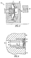
- FIG. 1 shows a presently preferred embodiment of the invention.
- This figure shows a purge valve, generally designated 10, which is for expelling liquid contaminants from a fluid conduit 33.
- Fluid conduit 33 is normally unpressurized but is at times pressurized with a gas which contains the liquid contaminant.
- Valve 10 includes a housing 12 which has a first housing portion 14 and a second housing portion 16.
- Valve 10 has a diaphragm 20 mounted within housing 12 and a control chamber 22 on a first side of diaphragm 20.
- Diaphragm 20 has a relatively flexible outer portion 42 surrounding a relatively stiff inner portion 40.
- Diaphragm 20 preferably has a ridge 44 for sealing in a circumferential groove 45 formed in housing 12. Preferably, it is clamped between first housing portion 14 and second housing portion 16. It is desirable for second housing portion 16 to be removable from first housing portion 14 so that valve 10 may be serviced. It should be noted that a seal (not shown) should also be provided around high impedance flowpath 34 at the interface between first housing portion 14 and second housing portion 16 to prevent leakage between these portions
- high impedance discharge flow path 34 have a higher impedance to fluid flow than exhaust passage 24.
- FIG 2 shows the configuration of valve 10 when fluid conduit 33 is pressurized.
- pressure in control chamber 22 presses diaphragm 20 against valve seat 26 so that valve 10 is closed.
- valve 10 Upon onset of pressurization, there is a brief time before diaphragm 20 seats against valve seat 26 during which the liquid contaminant is forcibly expelled through valve 10.
- valve 10 After diaphragm 20 is seated against valve seat 26, as long as pressure in conduit 33 remains above a minimum value established by the strength of spring 28, valve 10 remains closed.
- valve 10 opens to the configuration shown in Figure 1 so that liquid may drain from it.
- FIG 4 shows a removable flow restriction 48 which preferably is inserted in high impedance discharge flowpath 34.
- Flow restriction 48 preferably has an externally threaded portion 50 for engagement with internally threaded portion 52 of discharge flow path 34.
- Flow restriction 48 also have a socket 53, for example a hexagonal socket, to receive a wrench having a hexagonal exterior.
- Flow restriction 48 has choke portion 55.
- it also has a filter (not shown) to prevent debris from blocking choke portion 55.
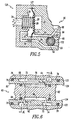
- valve seat 26 mounted on the second side of diaphragm 20, positioned so that diaphragm 20 may seal against valve seat 26. It also has a spring 28 located on the second side of diaphragm 20 to press it away from valve seat 26.
- Valve portion 120 also has annular chamber 30 on the second side of diaphragm 20. Annular chamber 30 surrounds exhaust passage 24 and annular chamber 30 is open to exhaust passage 24 when diaphragm 20 is not sealed against valve seat 26.
- Purge valve arrangement 90 also has a relatively low impedance flow path 92 between control chamber 22 and relatively dry connection point 64 of liquid separator 60. It also has a relatively high impedance discharge flow path between annular chamber 30 and relatively wet connection point 62. It is preferred that relatively dry connection point 64 be at a greater elevation than relatively wet connection point 62.
- valve portion 120 Whenever conduit 33 is unpressurized, valve portion 120 is open and liquid contaminants in conduit 33 drain from conduit 33 through high impedance discharge flow path 94 to annular chamber 30 and are purged from valve portion 120 through exhaust passage 24.
Landscapes
- Engineering & Computer Science (AREA)
- Transportation (AREA)
- Mechanical Engineering (AREA)
- Details Of Valves (AREA)
- Fluid-Driven Valves (AREA)
- Lift Valve (AREA)
Abstract
Description
Claims (21)
- A purge valve for expelling a liquid contaminant from a fluid conduit which is normally unpressurized but is at times pressurized with a gas which contains such liquid contaminant, said valve comprising:(a) a housing;(b) a diaphragm mounted within said housing;(c) a control chamber on a first side of said diaphragm;(d) an exhaust passage on a second side of said diaphragm;(e) a valve seat surrounding an upstream end of said exhaust passage, said valve seat positioned so that said diaphragm may seal against said valve seat;(f) a spring disposed on said second side of said diaphragm to provide a spring force on said diaphragm to press it away from said valve seat;(g) an annular chamber on said second side of said diaphragm, said annular chamber surrounding said exhaust passage, said annular chamber open to said exhaust passage when said diaphragm is unseated from said valve seat;(h) a relatively low impedance flow path connected to said control chamber, said relatively low impedance flow path connectable to such fluid conduit;(i) a relatively high impedance discharge flow path connected to said annular chamber, said relatively high impedance discharge flow path at least one of connected to said control chamber, connected to said low impedance flow path and connectable to such fluid conduit;so that when said valve is connected to such fluid conduit and whenever such fluid conduit is unpressurized said valve is open due to said spring force so that such liquid contaminant may drain from such fluid conduit through said high impedance discharge flow path to said annular chamber and thence be purged from said valve through said exhaust passage; andso that when such fluid conduit is pressurized for a brief time before said spring force is overcome by pressure in said control chamber, said valve remains open so that such liquid contaminant is forcefully expelled through said valve and after said brief time, when said pressure in said control chamber overcomes said spring force, said diaphragm is pressed against said valve seat so that said valve is closed.
- A purge valve according to claim 1 wherein said high impedance discharge flow path is connected to said control chamber.
- A purge valve according to claim 2 wherein said high impedance discharge flow path is connected to said control chamber at about the lowest portion thereof.
- A purge valve according to claim 1 wherein said high impedance discharge flow path is connected to said low impedance flow path.
- A purge valve according to claim 4 wherein said high impedance flow path is connected to said low impedance flow path at an elevation lower than a connection point of said control chamber and said low impedance flow path.
- A purge valve according to claim 1 wherein said valve seat is formed as an annular ridge surrounding said upstream end of said exhaust passage.
- A purge valve according to claim 6 wherein said annular ridge has a smooth convex surface on a side toward said diaphragm.
- A purge valve according to claim 1 wherein said diaphragm has a relatively stiff central portion and a relatively flexible annular outer portion.
- A purge valve according to claim 1 wherein said diaphragm has a circumferential ridge for sealing inside a circumferential groove formed in said housing.
- A purge valve according to claim 9 wherein said diaphragm is clamped between a first portion of said housing and a second portion of said housing.
- A purge valve according to claim 10 wherein said second portion of said housing can be removed from said first portion of said housing so that said valve can be serviced.
- A purge valve according to claim 1 wherein said relatively high impedance discharge flow path includes a removable flow restriction.
- A purge valve according to claim 12 wherein said removable flow restriction has a threaded exterior portion for engagement with an internally threaded portion of said high impedance discharge flow path.
- A purge valve according to claim 1 wherein said high impedance discharge flow path has a higher impedance than said exhaust passage.
- A purge valve according to claim 1 wherein said spring is mounted at least partially within said exhaust passage.
- A purge valve according to claim 15 wherein said exhaust passage has a relatively large diameter inner portion to enclose at least a portion of said spring and a relatively small diameter outer portion to provide an internal shoulder to support said spring.
- A purge valve arrangement for expelling a liquid contaminant from a fluid conduit which is normally unpressurized but is at times pressurized with a gas which contains such liquid contaminant, said arrangement comprising:(a) a liquid separator having a wet connection point and a relatively dry connection point, said wet connection point joined to such fluid conduit;(b) a purge valve having:(i) a housing;(ii) a diaphragm mounted within said housing;(iii) a control chamber on a first side of said diaphragm;(iv) an exhaust passage on a second side of said diaphragm;(v) a valve seat surrounding an upstream end of said exhaust passage, said valve seat positioned so that said diaphragm can seal against said valve seat;(vi) a spring disposed on said second side of said diaphragm to provide a spring force on said diaphragm to press it away from said valve seat;(vii) an annular chamber on said second side of said diaphragm, said annular chamber surrounding said exhaust passage, said annular chamber open to said exhaust passage when said diaphragm is unseated from said valve seat;(viii) a relatively low impedance flow path between said control chamber and said relatively dry connection point on said liquid separator;(ix) a relatively high impedance discharge flow path between said annular chamber and said wet connection point on said liquid separator;so that whenever such fluid conduit is unpressurized, such liquid contaminant may drain from such fluid conduit through said high impedance discharge flow path to said annular chamber and thence be purged from said valve through said exhaust passage; andso that when such fluid conduit is pressurized for a brief time before said spring force is overcome by pressure in said control chamber, said valve remains open so that such liquid contaminant is forcefully expelled through said valve and after said brief time, when said pressure in said control chamber overcomes said spring force, said diaphragm is pressed against said valve seat so that said valve is closed.
- A purge valve arrangement according to claim 17 wherein said relatively dry connection point on said liquid separator is at a greater elevation than said wet connection point on said liquid separator.
- A purge valve arrangement according to claim 18 wherein said liquid separator includes three annular separation chambers defined within said housing, each one of said three annular separation chambers oriented in a substantially vertical plane, said wet connection point being at a low point on a first one of said three annular separation chambers, said relatively dry connection point being at a high point on a third one of said three annular separation chambers, said first one of said three annular separation chambers being connected to a second one of said three annular separation chambers through a first plurality of relatively small passages, said second one of said three annular separation chambers being connected to said third one of said three annular separation chambers through a second plurality of relatively small passages.
- A purge valve arrangement according to claim 19 wherein said second one of said three annular separation chambers has a lesser diameter than said first one of said three annular separation chambers and a lesser diameter than said third one of said three annular separation chambers and wherein each of said first plurality of relatively small passages is oriented substantially radially and wherein each of said second plurality of relatively small passages is oriented substantially radially.
- A purge valve arrangement according to claim 20 wherein said first one of said three annular separation chambers and said third one of said three annular separation chambers is formed in an exterior surface of a bushing which is disposed within a substantially horizontal bore disposed in said housing, said second one of said three annular separation chambers being formed in an exterior surface of a core disposed within an inner surface of said bushing and each of said first plurality of relatively small passages is formed through said bushing from said first one of said three annular separation chambers to said inner surface of said bushing to connect to said second one of said three annular separation chambers and wherein each of said second plurality of relatively small passages is formed through said bushing from said third one of said three annular separation chambers to said inner surface of said bushing to connect to said second one of said three annular separation chambers.
Applications Claiming Priority (2)
| Application Number | Priority Date | Filing Date | Title |
|---|---|---|---|
| US379874 | 1999-08-24 | ||
| US09/379,874 US6170511B1 (en) | 1999-08-24 | 1999-08-24 | Normally open purge valve |
Publications (2)
| Publication Number | Publication Date |
|---|---|
| EP1078834A2 true EP1078834A2 (en) | 2001-02-28 |
| EP1078834A3 EP1078834A3 (en) | 2003-02-19 |
Family
ID=23499065
Family Applications (1)
| Application Number | Title | Priority Date | Filing Date |
|---|---|---|---|
| EP00117424A Withdrawn EP1078834A3 (en) | 1999-08-24 | 2000-08-11 | Normally open purge valve |
Country Status (7)
| Country | Link |
|---|---|
| US (1) | US6170511B1 (en) |
| EP (1) | EP1078834A3 (en) |
| AU (1) | AU756935B2 (en) |
| BR (1) | BR0003462A (en) |
| CA (1) | CA2314021A1 (en) |
| MX (1) | MXPA00008252A (en) |
| ZA (1) | ZA200003613B (en) |
Cited By (1)
| Publication number | Priority date | Publication date | Assignee | Title |
|---|---|---|---|---|
| WO2007110059A2 (en) | 2006-03-27 | 2007-10-04 | Hidde Axel R | Simple bleed valve with a membrane |
Families Citing this family (3)
| Publication number | Priority date | Publication date | Assignee | Title |
|---|---|---|---|---|
| US20070209705A1 (en) * | 2006-03-07 | 2007-09-13 | Nichols Randall W | Drain valve |
| US9834192B2 (en) | 2013-03-05 | 2017-12-05 | Haldex Brake Products Corporation | Automatic air tank purge system |
| US10502329B2 (en) | 2015-11-23 | 2019-12-10 | Haldex Brake Products Corporation | Reservoir purge valve |
Family Cites Families (10)
| Publication number | Priority date | Publication date | Assignee | Title |
|---|---|---|---|---|
| US1693646A (en) * | 1928-12-04 | farmer | ||
| US2610645A (en) * | 1952-09-16 | Automatic drain valve | ||
| US2866519A (en) * | 1957-04-22 | 1958-12-30 | Engman Mfg Company | Moisture and dust separator for air pressure lines |
| US3029830A (en) * | 1957-11-06 | 1962-04-17 | Garrett Corp | Servo valve |
| US2973773A (en) * | 1958-05-12 | 1961-03-07 | Penn Controls | Air volume control for water systems |
| US3659625A (en) * | 1970-02-16 | 1972-05-02 | Westinghouse Air Brake Co | Drain valve device |
| US3788592A (en) * | 1972-10-24 | 1974-01-29 | Westinghouse Bremsen Apparate | Wheel slip control apparatus having quick closing valves |
| SU1211501A1 (en) * | 1984-11-20 | 1986-02-15 | Белорусский Ордена Трудового Красного Знамени Политехнический Институт | Steam trap |
| JP3381120B2 (en) * | 1995-05-15 | 2003-02-24 | 株式会社テイエルブイ | Thermo-responsive steam trap |
| DE19647256A1 (en) * | 1996-11-15 | 1998-05-20 | Mann & Hummel Filter | Device for returning liquids in gas flows |
-
1999
- 1999-08-24 US US09/379,874 patent/US6170511B1/en not_active Expired - Fee Related
-
2000
- 2000-07-13 CA CA002314021A patent/CA2314021A1/en not_active Abandoned
- 2000-07-18 ZA ZA200003613A patent/ZA200003613B/en unknown
- 2000-07-20 AU AU48751/00A patent/AU756935B2/en not_active Ceased
- 2000-08-09 BR BR0003462-2A patent/BR0003462A/en not_active Application Discontinuation
- 2000-08-11 EP EP00117424A patent/EP1078834A3/en not_active Withdrawn
- 2000-08-23 MX MXPA00008252A patent/MXPA00008252A/en unknown
Cited By (1)
| Publication number | Priority date | Publication date | Assignee | Title |
|---|---|---|---|---|
| WO2007110059A2 (en) | 2006-03-27 | 2007-10-04 | Hidde Axel R | Simple bleed valve with a membrane |
Also Published As
| Publication number | Publication date |
|---|---|
| MXPA00008252A (en) | 2002-06-04 |
| AU756935B2 (en) | 2003-01-30 |
| EP1078834A3 (en) | 2003-02-19 |
| CA2314021A1 (en) | 2001-02-24 |
| AU4875100A (en) | 2001-03-01 |
| ZA200003613B (en) | 2001-01-31 |
| US6170511B1 (en) | 2001-01-09 |
| BR0003462A (en) | 2001-06-12 |
Similar Documents
| Publication | Publication Date | Title |
|---|---|---|
| EP2242673B1 (en) | Internal ventilating diaphragm piston brake actuator | |
| US8714318B2 (en) | Parking brake chamber internal breathing system | |
| JPS6050617B2 (en) | Fluid pressure brake device | |
| US4524800A (en) | One-way brake bleeder check valve with sealing cap | |
| SE455592B (en) | HYDRAULIC BRAKE SYSTEM WITH SLIR CONTROL AND SPEC WITH A BREASER VALVE USED IN BREATHING THE BRAKE SYSTEM BEFORE HEATING HYDRAULIC FLUID IN THE HEAD CYLINDER CONTAINER | |
| US6170511B1 (en) | Normally open purge valve | |
| US4478617A (en) | Strainer arrangement for combined dirt collector and cut out cocks | |
| US6164312A (en) | Purge valve | |
| US5683148A (en) | Brake pipe pneumatic valve | |
| US4043605A (en) | Emergency portion for a brake control valve | |
| US4145090A (en) | Continual quick service valve device | |
| CA2187001C (en) | An improved pneumatic pressure to hydraulic pressure intensifier mechanism | |
| US4397505A (en) | Control valve | |
| US2385151A (en) | Automatic blow-off valve apparatus | |
| US4175792A (en) | Continual quick service valve device | |
| US4002375A (en) | Service portion for brake control valves | |
| CA1278598C (en) | Protection valve for spring parking brake system | |
| JPS6019010Y2 (en) | Emergency valve for brake control | |
| US6132009A (en) | Remote brake application valve | |
| GB1587479A (en) | Brake control valve devices | |
| US2464968A (en) | Protection valve device | |
| US3468585A (en) | Repeater relay valve device | |
| JPS6232934Y2 (en) | ||
| US5722737A (en) | Brake release for railroad cars | |
| US966211A (en) | Air-brake system. |
Legal Events
| Date | Code | Title | Description |
|---|---|---|---|
| PUAI | Public reference made under article 153(3) epc to a published international application that has entered the european phase |
Free format text: ORIGINAL CODE: 0009012 |
|
| AK | Designated contracting states |
Kind code of ref document: A2 Designated state(s): AT BE CH CY DE DK ES FI FR GB GR IE IT LI LU MC NL PT SE |
|
| AX | Request for extension of the european patent |
Free format text: AL;LT;LV;MK;RO;SI |
|
| PUAL | Search report despatched |
Free format text: ORIGINAL CODE: 0009013 |
|
| AK | Designated contracting states |
Designated state(s): AT BE CH CY DE DK ES FI FR GB GR IE IT LI LU MC NL PT SE |
|
| AX | Request for extension of the european patent |
Extension state: AL LT LV MK RO SI |
|
| 17P | Request for examination filed |
Effective date: 20030325 |
|
| 17Q | First examination report despatched |
Effective date: 20030527 |
|
| AKX | Designation fees paid |
Designated state(s): DE FR GB IE |
|
| STAA | Information on the status of an ep patent application or granted ep patent |
Free format text: STATUS: THE APPLICATION IS DEEMED TO BE WITHDRAWN |
|
| 18D | Application deemed to be withdrawn |
Effective date: 20031007 |