EP1080765A1 - Multieffect distillation - Google Patents
Multieffect distillation Download PDFInfo
- Publication number
- EP1080765A1 EP1080765A1 EP00307506A EP00307506A EP1080765A1 EP 1080765 A1 EP1080765 A1 EP 1080765A1 EP 00307506 A EP00307506 A EP 00307506A EP 00307506 A EP00307506 A EP 00307506A EP 1080765 A1 EP1080765 A1 EP 1080765A1
- Authority
- EP
- European Patent Office
- Prior art keywords
- distillation column
- component
- distillation
- product stream
- stream
- Prior art date
- Legal status (The legal status is an assumption and is not a legal conclusion. Google has not performed a legal analysis and makes no representation as to the accuracy of the status listed.)
- Ceased
Links
- 238000004821 distillation Methods 0.000 title claims abstract description 219
- 239000000203 mixture Substances 0.000 claims abstract description 115
- 238000000034 method Methods 0.000 claims abstract description 70
- 230000008569 process Effects 0.000 claims abstract description 69
- 238000000926 separation method Methods 0.000 claims abstract description 26
- 239000007788 liquid Substances 0.000 claims description 50
- 239000012530 fluid Substances 0.000 claims description 15
- IJGRMHOSHXDMSA-UHFFFAOYSA-N Atomic nitrogen Chemical compound N#N IJGRMHOSHXDMSA-UHFFFAOYSA-N 0.000 claims description 14
- UHOVQNZJYSORNB-UHFFFAOYSA-N Benzene Chemical compound C1=CC=CC=C1 UHOVQNZJYSORNB-UHFFFAOYSA-N 0.000 claims description 9
- YXFVVABEGXRONW-UHFFFAOYSA-N Toluene Chemical compound CC1=CC=CC=C1 YXFVVABEGXRONW-UHFFFAOYSA-N 0.000 claims description 9
- 229930195733 hydrocarbon Natural products 0.000 claims description 9
- 150000002430 hydrocarbons Chemical class 0.000 claims description 9
- XKRFYHLGVUSROY-UHFFFAOYSA-N Argon Chemical compound [Ar] XKRFYHLGVUSROY-UHFFFAOYSA-N 0.000 claims description 8
- 239000004215 Carbon black (E152) Substances 0.000 claims description 6
- VNWKTOKETHGBQD-UHFFFAOYSA-N methane Chemical compound C VNWKTOKETHGBQD-UHFFFAOYSA-N 0.000 claims description 6
- 229910052786 argon Inorganic materials 0.000 claims description 4
- RCAJAIOZWUFVHZ-UHFFFAOYSA-N butane 2-methylbutane pentane Chemical compound CCCC.CCCCC.CCC(C)C RCAJAIOZWUFVHZ-UHFFFAOYSA-N 0.000 claims description 4
- YAIDLYRPOFNPHB-UHFFFAOYSA-N heptane;hexane;pentane Chemical compound CCCCC.CCCCCC.CCCCCCC YAIDLYRPOFNPHB-UHFFFAOYSA-N 0.000 claims description 4
- PXVTUBGXSTZVKK-UHFFFAOYSA-N hexane;2-methylbutane;pentane Chemical compound CCCCC.CCC(C)C.CCCCCC PXVTUBGXSTZVKK-UHFFFAOYSA-N 0.000 claims description 4
- UGFAIRIUMAVXCW-UHFFFAOYSA-N Carbon monoxide Chemical compound [O+]#[C-] UGFAIRIUMAVXCW-UHFFFAOYSA-N 0.000 claims description 3
- CTQNGGLPUBDAKN-UHFFFAOYSA-N O-Xylene Chemical compound CC1=CC=CC=C1C CTQNGGLPUBDAKN-UHFFFAOYSA-N 0.000 claims description 3
- 150000001298 alcohols Chemical class 0.000 claims description 3
- 229910002091 carbon monoxide Inorganic materials 0.000 claims description 3
- 229940110728 nitrogen / oxygen Drugs 0.000 claims description 3
- MWUXSHHQAYIFBG-UHFFFAOYSA-N nitrogen oxide Inorganic materials O=[N] MWUXSHHQAYIFBG-UHFFFAOYSA-N 0.000 claims description 3
- 239000008096 xylene Substances 0.000 claims description 3
- 238000010992 reflux Methods 0.000 description 13
- 238000009833 condensation Methods 0.000 description 5
- 230000005494 condensation Effects 0.000 description 5
- 238000010586 diagram Methods 0.000 description 5
- 229910052757 nitrogen Inorganic materials 0.000 description 4
- QVGXLLKOCUKJST-UHFFFAOYSA-N atomic oxygen Chemical compound [O] QVGXLLKOCUKJST-UHFFFAOYSA-N 0.000 description 3
- 238000001816 cooling Methods 0.000 description 3
- 239000001301 oxygen Substances 0.000 description 3
- 229910052760 oxygen Inorganic materials 0.000 description 3
- 238000012546 transfer Methods 0.000 description 3
- RYPKRALMXUUNKS-UHFFFAOYSA-N 2-Hexene Natural products CCCC=CC RYPKRALMXUUNKS-UHFFFAOYSA-N 0.000 description 2
- 239000000470 constituent Substances 0.000 description 2
- 230000007423 decrease Effects 0.000 description 2
- 238000004519 manufacturing process Methods 0.000 description 2
- GBMDVOWEEQVZKZ-UHFFFAOYSA-N methanol;hydrate Chemical compound O.OC GBMDVOWEEQVZKZ-UHFFFAOYSA-N 0.000 description 2
- 238000005086 pumping Methods 0.000 description 2
- 238000011084 recovery Methods 0.000 description 2
- 230000009467 reduction Effects 0.000 description 2
- MYMOFIZGZYHOMD-UHFFFAOYSA-N Dioxygen Chemical compound O=O MYMOFIZGZYHOMD-UHFFFAOYSA-N 0.000 description 1
- 230000008859 change Effects 0.000 description 1
- 230000000052 comparative effect Effects 0.000 description 1
- 230000003247 decreasing effect Effects 0.000 description 1
- 238000012938 design process Methods 0.000 description 1
- 238000005265 energy consumption Methods 0.000 description 1
- 238000010438 heat treatment Methods 0.000 description 1
- 230000006872 improvement Effects 0.000 description 1
- 230000010354 integration Effects 0.000 description 1
- 238000012986 modification Methods 0.000 description 1
- 230000004048 modification Effects 0.000 description 1
- 238000012856 packing Methods 0.000 description 1
- 238000012545 processing Methods 0.000 description 1
- 230000000717 retained effect Effects 0.000 description 1
- 238000009834 vaporization Methods 0.000 description 1
Images






Classifications
-
- F—MECHANICAL ENGINEERING; LIGHTING; HEATING; WEAPONS; BLASTING
- F25—REFRIGERATION OR COOLING; COMBINED HEATING AND REFRIGERATION SYSTEMS; HEAT PUMP SYSTEMS; MANUFACTURE OR STORAGE OF ICE; LIQUEFACTION SOLIDIFICATION OF GASES
- F25J—LIQUEFACTION, SOLIDIFICATION OR SEPARATION OF GASES OR GASEOUS OR LIQUEFIED GASEOUS MIXTURES BY PRESSURE AND COLD TREATMENT OR BY BRINGING THEM INTO THE SUPERCRITICAL STATE
- F25J3/00—Processes or apparatus for separating the constituents of gaseous or liquefied gaseous mixtures involving the use of liquefaction or solidification
- F25J3/02—Processes or apparatus for separating the constituents of gaseous or liquefied gaseous mixtures involving the use of liquefaction or solidification by rectification, i.e. by continuous interchange of heat and material between a vapour stream and a liquid stream
- F25J3/04—Processes or apparatus for separating the constituents of gaseous or liquefied gaseous mixtures involving the use of liquefaction or solidification by rectification, i.e. by continuous interchange of heat and material between a vapour stream and a liquid stream for air
- F25J3/04642—Recovering noble gases from air
- F25J3/04648—Recovering noble gases from air argon
- F25J3/04654—Producing crude argon in a crude argon column
- F25J3/04709—Producing crude argon in a crude argon column as an auxiliary column system in at least a dual pressure main column system
- F25J3/04715—The auxiliary column system simultaneously produces oxygen
-
- B—PERFORMING OPERATIONS; TRANSPORTING
- B01—PHYSICAL OR CHEMICAL PROCESSES OR APPARATUS IN GENERAL
- B01D—SEPARATION
- B01D3/00—Distillation or related exchange processes in which liquids are contacted with gaseous media, e.g. stripping
- B01D3/14—Fractional distillation or use of a fractionation or rectification column
- B01D3/143—Fractional distillation or use of a fractionation or rectification column by two or more of a fractionation, separation or rectification step
- B01D3/146—Multiple effect distillation
-
- F—MECHANICAL ENGINEERING; LIGHTING; HEATING; WEAPONS; BLASTING
- F25—REFRIGERATION OR COOLING; COMBINED HEATING AND REFRIGERATION SYSTEMS; HEAT PUMP SYSTEMS; MANUFACTURE OR STORAGE OF ICE; LIQUEFACTION SOLIDIFICATION OF GASES
- F25J—LIQUEFACTION, SOLIDIFICATION OR SEPARATION OF GASES OR GASEOUS OR LIQUEFIED GASEOUS MIXTURES BY PRESSURE AND COLD TREATMENT OR BY BRINGING THEM INTO THE SUPERCRITICAL STATE
- F25J3/00—Processes or apparatus for separating the constituents of gaseous or liquefied gaseous mixtures involving the use of liquefaction or solidification
- F25J3/02—Processes or apparatus for separating the constituents of gaseous or liquefied gaseous mixtures involving the use of liquefaction or solidification by rectification, i.e. by continuous interchange of heat and material between a vapour stream and a liquid stream
- F25J3/0295—Start-up or control of the process; Details of the apparatus used, e.g. sieve plates, packings
-
- F—MECHANICAL ENGINEERING; LIGHTING; HEATING; WEAPONS; BLASTING
- F25—REFRIGERATION OR COOLING; COMBINED HEATING AND REFRIGERATION SYSTEMS; HEAT PUMP SYSTEMS; MANUFACTURE OR STORAGE OF ICE; LIQUEFACTION SOLIDIFICATION OF GASES
- F25J—LIQUEFACTION, SOLIDIFICATION OR SEPARATION OF GASES OR GASEOUS OR LIQUEFIED GASEOUS MIXTURES BY PRESSURE AND COLD TREATMENT OR BY BRINGING THEM INTO THE SUPERCRITICAL STATE
- F25J3/00—Processes or apparatus for separating the constituents of gaseous or liquefied gaseous mixtures involving the use of liquefaction or solidification
- F25J3/02—Processes or apparatus for separating the constituents of gaseous or liquefied gaseous mixtures involving the use of liquefaction or solidification by rectification, i.e. by continuous interchange of heat and material between a vapour stream and a liquid stream
- F25J3/04—Processes or apparatus for separating the constituents of gaseous or liquefied gaseous mixtures involving the use of liquefaction or solidification by rectification, i.e. by continuous interchange of heat and material between a vapour stream and a liquid stream for air
- F25J3/04406—Processes or apparatus for separating the constituents of gaseous or liquefied gaseous mixtures involving the use of liquefaction or solidification by rectification, i.e. by continuous interchange of heat and material between a vapour stream and a liquid stream for air using a dual pressure main column system
- F25J3/04412—Processes or apparatus for separating the constituents of gaseous or liquefied gaseous mixtures involving the use of liquefaction or solidification by rectification, i.e. by continuous interchange of heat and material between a vapour stream and a liquid stream for air using a dual pressure main column system in a classical double column flowsheet, i.e. with thermal coupling by a main reboiler-condenser in the bottom of low pressure respectively top of high pressure column
-
- F—MECHANICAL ENGINEERING; LIGHTING; HEATING; WEAPONS; BLASTING
- F25—REFRIGERATION OR COOLING; COMBINED HEATING AND REFRIGERATION SYSTEMS; HEAT PUMP SYSTEMS; MANUFACTURE OR STORAGE OF ICE; LIQUEFACTION SOLIDIFICATION OF GASES
- F25J—LIQUEFACTION, SOLIDIFICATION OR SEPARATION OF GASES OR GASEOUS OR LIQUEFIED GASEOUS MIXTURES BY PRESSURE AND COLD TREATMENT OR BY BRINGING THEM INTO THE SUPERCRITICAL STATE
- F25J3/00—Processes or apparatus for separating the constituents of gaseous or liquefied gaseous mixtures involving the use of liquefaction or solidification
- F25J3/02—Processes or apparatus for separating the constituents of gaseous or liquefied gaseous mixtures involving the use of liquefaction or solidification by rectification, i.e. by continuous interchange of heat and material between a vapour stream and a liquid stream
- F25J3/04—Processes or apparatus for separating the constituents of gaseous or liquefied gaseous mixtures involving the use of liquefaction or solidification by rectification, i.e. by continuous interchange of heat and material between a vapour stream and a liquid stream for air
- F25J3/04406—Processes or apparatus for separating the constituents of gaseous or liquefied gaseous mixtures involving the use of liquefaction or solidification by rectification, i.e. by continuous interchange of heat and material between a vapour stream and a liquid stream for air using a dual pressure main column system
- F25J3/0443—A main column system not otherwise provided, e.g. a modified double column flowsheet
-
- F—MECHANICAL ENGINEERING; LIGHTING; HEATING; WEAPONS; BLASTING
- F25—REFRIGERATION OR COOLING; COMBINED HEATING AND REFRIGERATION SYSTEMS; HEAT PUMP SYSTEMS; MANUFACTURE OR STORAGE OF ICE; LIQUEFACTION SOLIDIFICATION OF GASES
- F25J—LIQUEFACTION, SOLIDIFICATION OR SEPARATION OF GASES OR GASEOUS OR LIQUEFIED GASEOUS MIXTURES BY PRESSURE AND COLD TREATMENT OR BY BRINGING THEM INTO THE SUPERCRITICAL STATE
- F25J3/00—Processes or apparatus for separating the constituents of gaseous or liquefied gaseous mixtures involving the use of liquefaction or solidification
- F25J3/02—Processes or apparatus for separating the constituents of gaseous or liquefied gaseous mixtures involving the use of liquefaction or solidification by rectification, i.e. by continuous interchange of heat and material between a vapour stream and a liquid stream
- F25J3/04—Processes or apparatus for separating the constituents of gaseous or liquefied gaseous mixtures involving the use of liquefaction or solidification by rectification, i.e. by continuous interchange of heat and material between a vapour stream and a liquid stream for air
- F25J3/04642—Recovering noble gases from air
- F25J3/04648—Recovering noble gases from air argon
- F25J3/04654—Producing crude argon in a crude argon column
- F25J3/04709—Producing crude argon in a crude argon column as an auxiliary column system in at least a dual pressure main column system
-
- F—MECHANICAL ENGINEERING; LIGHTING; HEATING; WEAPONS; BLASTING
- F25—REFRIGERATION OR COOLING; COMBINED HEATING AND REFRIGERATION SYSTEMS; HEAT PUMP SYSTEMS; MANUFACTURE OR STORAGE OF ICE; LIQUEFACTION SOLIDIFICATION OF GASES
- F25J—LIQUEFACTION, SOLIDIFICATION OR SEPARATION OF GASES OR GASEOUS OR LIQUEFIED GASEOUS MIXTURES BY PRESSURE AND COLD TREATMENT OR BY BRINGING THEM INTO THE SUPERCRITICAL STATE
- F25J3/00—Processes or apparatus for separating the constituents of gaseous or liquefied gaseous mixtures involving the use of liquefaction or solidification
- F25J3/02—Processes or apparatus for separating the constituents of gaseous or liquefied gaseous mixtures involving the use of liquefaction or solidification by rectification, i.e. by continuous interchange of heat and material between a vapour stream and a liquid stream
- F25J3/04—Processes or apparatus for separating the constituents of gaseous or liquefied gaseous mixtures involving the use of liquefaction or solidification by rectification, i.e. by continuous interchange of heat and material between a vapour stream and a liquid stream for air
- F25J3/04763—Start-up or control of the process; Details of the apparatus used
- F25J3/04769—Operation, control and regulation of the process; Instrumentation within the process
- F25J3/04793—Rectification, e.g. columns; Reboiler-condenser
-
- F—MECHANICAL ENGINEERING; LIGHTING; HEATING; WEAPONS; BLASTING
- F25—REFRIGERATION OR COOLING; COMBINED HEATING AND REFRIGERATION SYSTEMS; HEAT PUMP SYSTEMS; MANUFACTURE OR STORAGE OF ICE; LIQUEFACTION SOLIDIFICATION OF GASES
- F25J—LIQUEFACTION, SOLIDIFICATION OR SEPARATION OF GASES OR GASEOUS OR LIQUEFIED GASEOUS MIXTURES BY PRESSURE AND COLD TREATMENT OR BY BRINGING THEM INTO THE SUPERCRITICAL STATE
- F25J2200/00—Processes or apparatus using separation by rectification
- F25J2200/04—Processes or apparatus using separation by rectification in a dual pressure main column system
-
- F—MECHANICAL ENGINEERING; LIGHTING; HEATING; WEAPONS; BLASTING
- F25—REFRIGERATION OR COOLING; COMBINED HEATING AND REFRIGERATION SYSTEMS; HEAT PUMP SYSTEMS; MANUFACTURE OR STORAGE OF ICE; LIQUEFACTION SOLIDIFICATION OF GASES
- F25J—LIQUEFACTION, SOLIDIFICATION OR SEPARATION OF GASES OR GASEOUS OR LIQUEFIED GASEOUS MIXTURES BY PRESSURE AND COLD TREATMENT OR BY BRINGING THEM INTO THE SUPERCRITICAL STATE
- F25J2200/00—Processes or apparatus using separation by rectification
- F25J2200/04—Processes or apparatus using separation by rectification in a dual pressure main column system
- F25J2200/06—Processes or apparatus using separation by rectification in a dual pressure main column system in a classical double column flow-sheet, i.e. with thermal coupling by a main reboiler-condenser in the bottom of low pressure respectively top of high pressure column
-
- F—MECHANICAL ENGINEERING; LIGHTING; HEATING; WEAPONS; BLASTING
- F25—REFRIGERATION OR COOLING; COMBINED HEATING AND REFRIGERATION SYSTEMS; HEAT PUMP SYSTEMS; MANUFACTURE OR STORAGE OF ICE; LIQUEFACTION SOLIDIFICATION OF GASES
- F25J—LIQUEFACTION, SOLIDIFICATION OR SEPARATION OF GASES OR GASEOUS OR LIQUEFIED GASEOUS MIXTURES BY PRESSURE AND COLD TREATMENT OR BY BRINGING THEM INTO THE SUPERCRITICAL STATE
- F25J2200/00—Processes or apparatus using separation by rectification
- F25J2200/50—Processes or apparatus using separation by rectification using multiple (re-)boiler-condensers at different heights of the column
-
- F—MECHANICAL ENGINEERING; LIGHTING; HEATING; WEAPONS; BLASTING
- F25—REFRIGERATION OR COOLING; COMBINED HEATING AND REFRIGERATION SYSTEMS; HEAT PUMP SYSTEMS; MANUFACTURE OR STORAGE OF ICE; LIQUEFACTION SOLIDIFICATION OF GASES
- F25J—LIQUEFACTION, SOLIDIFICATION OR SEPARATION OF GASES OR GASEOUS OR LIQUEFIED GASEOUS MIXTURES BY PRESSURE AND COLD TREATMENT OR BY BRINGING THEM INTO THE SUPERCRITICAL STATE
- F25J2200/00—Processes or apparatus using separation by rectification
- F25J2200/50—Processes or apparatus using separation by rectification using multiple (re-)boiler-condensers at different heights of the column
- F25J2200/52—Processes or apparatus using separation by rectification using multiple (re-)boiler-condensers at different heights of the column in the high pressure column of a double pressure main column system
-
- F—MECHANICAL ENGINEERING; LIGHTING; HEATING; WEAPONS; BLASTING
- F25—REFRIGERATION OR COOLING; COMBINED HEATING AND REFRIGERATION SYSTEMS; HEAT PUMP SYSTEMS; MANUFACTURE OR STORAGE OF ICE; LIQUEFACTION SOLIDIFICATION OF GASES
- F25J—LIQUEFACTION, SOLIDIFICATION OR SEPARATION OF GASES OR GASEOUS OR LIQUEFIED GASEOUS MIXTURES BY PRESSURE AND COLD TREATMENT OR BY BRINGING THEM INTO THE SUPERCRITICAL STATE
- F25J2200/00—Processes or apparatus using separation by rectification
- F25J2200/50—Processes or apparatus using separation by rectification using multiple (re-)boiler-condensers at different heights of the column
- F25J2200/54—Processes or apparatus using separation by rectification using multiple (re-)boiler-condensers at different heights of the column in the low pressure column of a double pressure main column system
-
- F—MECHANICAL ENGINEERING; LIGHTING; HEATING; WEAPONS; BLASTING
- F25—REFRIGERATION OR COOLING; COMBINED HEATING AND REFRIGERATION SYSTEMS; HEAT PUMP SYSTEMS; MANUFACTURE OR STORAGE OF ICE; LIQUEFACTION SOLIDIFICATION OF GASES
- F25J—LIQUEFACTION, SOLIDIFICATION OR SEPARATION OF GASES OR GASEOUS OR LIQUEFIED GASEOUS MIXTURES BY PRESSURE AND COLD TREATMENT OR BY BRINGING THEM INTO THE SUPERCRITICAL STATE
- F25J2200/00—Processes or apparatus using separation by rectification
- F25J2200/90—Details relating to column internals, e.g. structured packing, gas or liquid distribution
-
- F—MECHANICAL ENGINEERING; LIGHTING; HEATING; WEAPONS; BLASTING
- F25—REFRIGERATION OR COOLING; COMBINED HEATING AND REFRIGERATION SYSTEMS; HEAT PUMP SYSTEMS; MANUFACTURE OR STORAGE OF ICE; LIQUEFACTION SOLIDIFICATION OF GASES
- F25J—LIQUEFACTION, SOLIDIFICATION OR SEPARATION OF GASES OR GASEOUS OR LIQUEFIED GASEOUS MIXTURES BY PRESSURE AND COLD TREATMENT OR BY BRINGING THEM INTO THE SUPERCRITICAL STATE
- F25J2200/00—Processes or apparatus using separation by rectification
- F25J2200/90—Details relating to column internals, e.g. structured packing, gas or liquid distribution
- F25J2200/94—Details relating to the withdrawal point
-
- F—MECHANICAL ENGINEERING; LIGHTING; HEATING; WEAPONS; BLASTING
- F25—REFRIGERATION OR COOLING; COMBINED HEATING AND REFRIGERATION SYSTEMS; HEAT PUMP SYSTEMS; MANUFACTURE OR STORAGE OF ICE; LIQUEFACTION SOLIDIFICATION OF GASES
- F25J—LIQUEFACTION, SOLIDIFICATION OR SEPARATION OF GASES OR GASEOUS OR LIQUEFIED GASEOUS MIXTURES BY PRESSURE AND COLD TREATMENT OR BY BRINGING THEM INTO THE SUPERCRITICAL STATE
- F25J2235/00—Processes or apparatus involving steps for increasing the pressure or for conveying of liquid process streams
- F25J2235/02—Processes or apparatus involving steps for increasing the pressure or for conveying of liquid process streams using a pump in general or hydrostatic pressure increase
-
- F—MECHANICAL ENGINEERING; LIGHTING; HEATING; WEAPONS; BLASTING
- F25—REFRIGERATION OR COOLING; COMBINED HEATING AND REFRIGERATION SYSTEMS; HEAT PUMP SYSTEMS; MANUFACTURE OR STORAGE OF ICE; LIQUEFACTION SOLIDIFICATION OF GASES
- F25J—LIQUEFACTION, SOLIDIFICATION OR SEPARATION OF GASES OR GASEOUS OR LIQUEFIED GASEOUS MIXTURES BY PRESSURE AND COLD TREATMENT OR BY BRINGING THEM INTO THE SUPERCRITICAL STATE
- F25J2245/00—Processes or apparatus involving steps for recycling of process streams
- F25J2245/02—Recycle of a stream in general, e.g. a by-pass stream
-
- F—MECHANICAL ENGINEERING; LIGHTING; HEATING; WEAPONS; BLASTING
- F25—REFRIGERATION OR COOLING; COMBINED HEATING AND REFRIGERATION SYSTEMS; HEAT PUMP SYSTEMS; MANUFACTURE OR STORAGE OF ICE; LIQUEFACTION SOLIDIFICATION OF GASES
- F25J—LIQUEFACTION, SOLIDIFICATION OR SEPARATION OF GASES OR GASEOUS OR LIQUEFIED GASEOUS MIXTURES BY PRESSURE AND COLD TREATMENT OR BY BRINGING THEM INTO THE SUPERCRITICAL STATE
- F25J2290/00—Other details not covered by groups F25J2200/00 - F25J2280/00
- F25J2290/40—Vertical layout or arrangement of cold equipments within in the cold box, e.g. columns, condensers, heat exchangers etc.
Definitions
- the present invention pertains to the field of distillation of fluid mixtures, and in particular to multieffect distillation processes to separate multicomponent mixtures containing three or more components into four product streams each enriched in one of the components.
- Multieffect distillation has long been considered as one of the methods to reduce energy consumption in distillation columns.
- two heat integrated distillation columns are used. This heat integration is achieved by operating one column at a higher pressure than the other. Feed is fed to one of the distillation columns. The vapour from the top of the high pressure column is condensed by heat exchange with the liquid at the bottom of the low pressure column. Thus, the vapour in the high pressure column provides the boilup duty for the low pressure column.
- US-A-5,245,832 discloses a multieffect distillation process consisting of three distillation columns to separate air into three product streams each enriched in oxygen, argon and nitrogen respectively.
- the ternary feed mixture 100 is fed to an intermediate location of the high pressure column 110.
- a location of a distillation column is an "intermediate location” when there is at least one separation stage above and one separation stage below that location.
- a “separation stage” is a mass transfer contact device between liquid and vapour phases, such as a suitable mass transfer tray or a packed height of a suitable packing.
- the vapour stream 184 enriched in component A from the top of the high pressure column is condensed in the reboiler/condenser 116.
- a portion of the condensed stream 186 provides the reflux for the high pressure column and the other portion provides the A-enriched product stream 190.
- A-lean binary stream 140 that is enriched in components B and C is recovered as stream 142.
- the pressure of this stream is reduced across valve 130 and fed to the low pressure column 120.
- a product stream 198 enriched in component B is produced from the top of the low pressure column, and product stream 194 enriched in the heaviest component C is produced from the bottom of this column.
- the boilup at the bottom of the low pressure column is provided by vaporising some bottom liquid in the reboiler/condenser 116. This reboiler/condenser provides thermal linking between the high pressure column and the low pressure column.
- the boilup at the bottom of the high pressure column 110 is provided through reboiler 112 and the condensing duty and the liquid reflux for the low pressure column 120 is provided through condenser 114.
- the prior art process in Figure 2 is similar to the one in Figure 1 in that it also uses a high pressure column 110 and a low pressure column 120 that are thermally linked through a reboiler/condenser 116.
- the feed stream 100 is now fed to an intermediate location of the low pressure column, and the product stream 190 enriched in the most volatile component A is recovered from the top of this column.
- the A-lean and essentially binary stream 140 containing components B and C is now collected from the bottom of the low pressure column and is increased in pressure across a pump 236 and then fed as stream 144 to the high pressure column 110.
- the high pressure column produces two product streams (198,194) each enriched in components B and C respectively.
- the boilup at the bottom of the high pressure column 110 is provided through reboiler 112 and the condensing duty and the liquid reflux for the low pressure column 120 is provided through condenser 114.
- the prior art process of Figure 3 is similar to the one in Figure 1 in that it also uses a high pressure column 110 and a low pressure column 120 that are thermally linked through a reboiler/condenser 116.
- the feed stream 100 also is fed to an intermediate location of the high pressure column.
- a product stream 194 enriched in the heaviest component C is produced from the bottom of this column.
- the vapour stream 350 at the top of the high pressure column is now lean in C but rich in both components A and B.
- a portion of the condensed stream 352 is withdrawn as stream 356, reduced in pressure across a valve 330 and fed to the low pressure column.
- the product streams (190, 198) enriched in components A and B are produced from the low pressure column.
- the boilup at the bottom of the high pressure column 110 is provided through reboiler 112 and the condensing duty and the liquid reflux for the low pressure column 120 is provided through condenser 114.
- the prior art process of Figure 4 also uses a high pressure column 110 and a low pressure column 120 thermally linked through a reboiler/condenser 116.
- the feed mixture 100 is fed to an intermediate location of the low pressure column.
- the C-enriched product stream 194 is recovered from the bottom of the low pressure column.
- a mixture lean in C but rich in A and B is recovered as stream 356 from the top of the low pressure column, pumped through pump 436 and fed to the high pressure column.
- the high pressure column produces the A-enriched and the B-enriched product streams (190, 198).
- the boilup at the bottom of the high pressure column 110 is provided through reboiler 112 and the condensing duty and the liquid reflux for the low pressure column 120 is provided through condenser 114.
- a common feature of all the prior art processes in Figures 1 through 4 is that the ternary feed mixture is fed to one of the two thermally linked columns.
- the feed In the distillation column , the feed is distilled into a product stream at one end and an essentially binary mixture stream at the other end.
- the binary mixture is then fed to the other distillation column and a product stream is recovered from each end of this distillation column .
- three product streams each enriched in one of the components is produced.
- the present invention is a multieffect distillation process which separates multicomponent mixtures containing three or more components into at least four product streams each enriched in one of the four components.
- a first aspect of the invention is a process for multieffect distillation of a multicomponent fluid containing at least three components, each component having a different volatility, into at least four product streams.
- the process uses a first distillation column operating at a first pressure and a second distillation column operating at a different second pressure, wherein the first and second distillation columns are thermally linked.
- the multicomponent fluid is fed into the first distillation column at a first intermediate location and at least a portion of a first component separated from the other components of the multicomponent fluid in the first distillation column, thereby forming a mixture stream lean in the first component.
- the portion of the first component is removed from the first distillation column in a first product stream rich in the first component.
- the mixture stream is removed from the first distillation column and fed into the second distillation column where at least a portion of a second component and at least a portion of a third component are separated from the mixture stream.
- the at least a portion of the second component is removed from the second distillation column in a second product stream rich in the second component and the at least a portion of the third component is removed from the second distillation column in a third product stream rich in the third component.
- a fourth product stream rich in the second or third component is removed from the first distillation column.
- the multicomponent fluid selected from nitrogen/oxygen/argon mixtures, benzene/toluene/xylene mixtures, nitrogen/carbon monoxide/methane mixtures, combinations of three or more components from C 1 to C 5 alcohols, and hydrocarbon mixtures, said hydrocarbon mixtures being selected from pentane-hexane-heptane, isopentane-pentane-hexane, butane-isopentane-pentane, iso-butane-n-butane-gasoline, and combinations of three or more components from C 1 to C 6 hydrocarbons or C 4 isomers.
- the mixture stream is withdrawn from the first distillation column at a location which is below the first intermediate location and at least one separation stage above the bottom of the first distillation column.
- the mixture stream is withdrawn from the first distillation column at a location which is above the first intermediate location and at least one separation stage below the top of the first distillation column.
- the fourth product stream can be rich in the component having the highest volatility and removed from the top of the first distillation column.
- the fourth product stream can be rich in the component having the lowest volatility and removed from the bottom of the first distillation column.
- the first pressure can be higher or lower than the second pressure and the mixture stream can be withdrawn from the first distillation column as a liquid or as a vapour.
- the first and second distillation columns suitably are thermally linked by condensing at least a portion of a vapour stream from the top of the high pressure distillation column by heat exchange against at least a portion of a bottoms liquid from the bottom of the low pressure distillation column.
- the mixture stream can be withdrawn from the first distillation column as a liquid or as a vapour.
- Another aspect of the present invention is a cryogenic air separation incorporating a process of the invention.
- the product stream rich in the component having the highest volatility is withdrawn from the top of the first distillation column; the product stream rich in the component having the lowest volatility is withdrawn from the bottom of the first distillation column; the mixture stream withdrawn from the first distillation column is rich in the component having an intermediate volatility and lean in either the component having the highest volatility or the component having the lowest volatility; a product stream rich in one of the components of the mixture stream is withdrawn from the top of the second distillation column; and a product stream rich in another of the components of the mixture stream is withdrawn from the bottom of the second distillation column.
- the product stream withdrawn from the top of the second distillation column will be rich in the component of intermediate volatility and the product stream withdrawn from bottom of the second distillation column will be rich in the component having the lowest volatility.
- the product stream collected from the bottom of the second distillation column will be rich in the component having the intermediate volatility and the product stream withdrawn from the top of the second distillation column will be rich in the component having the highest volatility.
- the present invention also provides apparatus for a multieffect distillation by the process of the first aspect invention of a multicomponent fluid containing at least three components, each component having a different volatility, said apparatus comprising:
- the current invention provides more efficient multieffect distillation processes. It is a process for the distillation of a multicomponent stream containing three or more components into at least four product streams by using two thermally linked distillation columns, wherein one of the distillation columns operates at a higher pressure and the other distillation column operates at a lower pressure, and thermal linking is achieved by condensing a vapour stream from the high pressure column by heat exchange against a liquid stream in the low pressure column to provide some boilup to the lower pressure column.
- the process comprises the following steps:
- the thermal linking is achieved by condensing the vapour from the top of the high pressure column against the liquid from the bottom of the low pressure column. This provides the vapour boilup for the low pressure column.
- the vapour from the top of the high pressure column could provide a boilup at an intermediate location of the low pressure column.
- the vapour from an intermediate location of the high pressure column could be condensed against the liquid at the bottom of the low pressure column.
- a vapour stream could be withdrawn from a suitable location of the high pressure column and condensed by heat exchange against the liquid from a suitable location of the low pressure column.
- some additional boilup duty to the low pressure column can be provided by using a heat source besides the condensation of a vapour stream from the high pressure column.
- some additional condensing duty to the high pressure column can be provided by using a cooling source besides the vaporisation of the liquid from the low pressure column.
- the first distillation column receiving the feed can be either the high pressure column or the low pressure column.
- the mixture stream in step (ii) is let down in pressure and fed to the low pressure column.
- the pressure can be let down across a valve or an expander generating work.
- the mixture stream in step (ii) is increased in pressure and fed to the high pressure column. The increase in pressure is achieved either by the use of a pump or a compressor or by gravitational head.
- the mixture stream in step (ii) is taken out as a liquid stream from the first distillation column and the withdrawal location is at an intermediate location of this distillation column .
- this mixture stream could be taken out either as a vapour or a two-phase stream.
- the enthalpy of this mixture stream after the withdrawal from the first distillation column could be changed by a suitable heat exchange prior to feeding it to the second distillation column.
- the mixture stream is fed to an intermediate location of the second distillation column. However, if needed, it could be fed to the top of the distillation column when the second distillation column is the low pressure column or to the bottom of the distillation column when the second distillation column is the high pressure column.
- Any product stream could be produced as a liquid or a vapour or a two-phase stream. It also is possible to produce multiple product streams in different thermodynamic states from any one end of a distillation column. If needed, a product stream could be produced from an intermediate location of a distillation column. Prior to the introduction of the feed to the first distillation column, its enthalpy could be adjusted by a suitable heat exchange. In some instances, more than one feed stream could be fed to the first distillation column. These feed streams could be of the same composition but of different specific enthalpies. It also is possible for these feed streams to have different compositions.
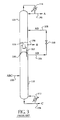
- Figure 5 shows a process according to the current invention where the first distillation column is a high pressure column 110 and the second distillation column is a low pressure column 120.
- the feed mixture ABC (stream 100) is fed to an intermediate location of the high pressure column 110.
- the vapour stream 184 from the top of the high pressure column is enriched in the most volatile major component A. At least a portion of this vapour stream is condensed in reboiler/condenser 116. A portion of this condensed stream 186 is recovered as a product stream 190 enriched in component A and the other portion is sent as liquid reflux to the high pressure column.
- a portion of the vapour stream 184 also could be recovered as a product stream enriched in component A.
- the boilup at the bottom of the high pressure column 110 is provided through reboiler 512.
- a portion of the bottom liquid 540 is recovered as a product stream 196 enriched in the least volatile major component C.
- a portion of the vapour stream exiting reboiler 512 also could be recovered as a product stream enriched in component C.
- a liquid mixture stream 142 lean in the most volatile major component A but containing both components B and C is withdrawn from a location below the feed location but at least one separation stage above the bottom of the high pressure column 110.
- the pressure of this liquid mixture is reduced across valve 130 and is fed to the low pressure column 120 as stream 144.
- this stream 144 is fed at an intermediate location.
- the boilup to the low pressure column is provided through thermal linking through reboiler/condenser 116 where at least a portion of the bottom liquid is vaporised by heat exchange.
- a product stream 198 rich in the component of intermediate volatility B is produced from the top of the low pressure column and a product stream 194 rich in the least volatile component C is produced from the bottom of this distillation column.
- the condensing duty and the liquid reflux for the low pressure column is provided through condenser 114.
- the stream 144 could be fed to the top of the low pressure column 120. In such a case there may not be a need for condenser 114.
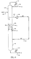
- Figure 6 shows another process according to the current invention where the first distillation column is the low pressure column 120 and the second distillation column is the high pressure column 110.
- the feed 100 is fed to an intermediate location of the low pressure column.
- a product stream 190 enriched in the most volatile major component A is produced from the top of the low pressure column.
- a product stream 194 enriched in the least volatile major component C is produced from the bottom of the low pressure column.
- a liquid mixture stream 642 lean in the most volatile major component A but containing components B and C is withdrawn from a location below the feed but at least one separation stage above the bottom of the low pressure column. This liquid stream is then pumped through pump 636 and fed as stream 644 to the high pressure column 110.
- a product stream 198 rich in major component B of intermediate volatility is produced from the top of the high pressure column and a product stream rich in the least volatile major component C is collected from the bottom of this column.
- the boilup at the bottom of the high pressure column 110 is provided through reboiler 612 and the condensing duty and the liquid reflux for the low pressure column 120 is provided through condenser 114.
- the composition of product streams 194 and 196 each rich in the least volatile major component C may or may not be the same. If needed, both of these streams could be mixed to provide one product stream.
- the mixture 644 lean in the most volatile major component A is fed at an intermediate location of the high pressure column 110 to produce relatively pure C-rich stream 196.
- the product stream 196 may not be desired to be of high purity in C.
- no separation stages may be used below the feed stream 644 to the high pressure column.
- the liquid from the bottom of the high pressure column will be sent to a partial reboiler 612, i.e., the exiting phase of the stream from the reboiler will be two-phase and while the vapour would be sent as boilup to the bottom of the high pressure column the liquid would be collected as product stream 196.
- the feed to the first distillation column is distilled such that the mixture stream transferred from the first distillation column to the second distillation column is lean in the most volatile major component A. It also is possible to design processes where such a mixture stream is lean in the least volatile major component C. This is achieved by withdrawing the mixture stream from the first distillation column at a location that is above the feed point to the distillation column.
- Figures 7 and 8 show examples of two such processes.
- both of these streams could be mixed to provide one product stream.
- the product stream 196 at the bottom of the high pressure column is enriched in the least volatile major component C.
- the boilup at the bottom of the high pressure column 110 is provided through reboiler 712 and the condensing duty and the liquid reflux for the low pressure column 120 is provided through condenser 114.
- the separation stages above the mixture stream 758 feed to the low pressure column are optional.
- the process in Figure 8 is similar to the one in Figure 7 with the major difference that the first distillation column is now the low pressure column 120 and the feed 100 is therefore fed to the low pressure column.
- the mixture stream 856 is withdrawn from a location above the feed but at least one separation stage below the top from the low pressure column and after pumping through pump 836 is fed to the high pressure column.
- From the bottom of the high pressure column 110 a product stream 198 rich in the major component of intermediate volatility B is recovered, and from the top of the low pressure column 120 a product stream 892 rich in the most volatile major component A is withdrawn.
- Another A-enriched process stream 190 is produced by the high pressure column and the C-enriched product stream 194 is produced by the low pressure column.
- the boilup at the bottom of the high pressure column 110 is provided through reboiler 812 and the condensing duty and the liquid reflux for the low pressure column 120 is provided through condenser 114. Similar to the process of Figure 6, separation stages below the mixture stream feed point to the high pressure column may not be used in certain applications.
- the first distillation column produces a product stream enriched in the most volatile major component A from the top and a product stream enriched in the least volatile major component C from the bottom.
- the second distillation column produces a product stream rich in the major component of intermediate volatility B from one of the ends of this distillation column.
- the processes in Figures 5 and 6 recover a second product stream rich in the least volatile major component C from the bottom of the second distillation column
- the processes in Figures 7 and 8 recover a second product stream rich in the most volatile major component A from the top of the second distillation column.
- the mixture stream according to step (ii) is shown to be withdrawn as a liquid stream from the first distillation column.
- a vapour mixture may be withdrawn from the first distillation column and fed to the second distillation column.
- the mixture stream 142 may be a vapour stream which, after a drop in pressure either across a valve 130 or a turbo expander, is fed to the low pressure column 120.
- the original liquid mixture stream 142 may be retained and another vapour stream is withdrawn from the high pressure column 110 below the feed location and, after a drop in pressure, is fed to a suitable location of the low pressure column.
- Another feature of the current invention is that additional reboilers and condensers may be used to make multieffect distillation processes more efficient. For example, rather than condensing all the vapour from the high pressure column in a reboiler/condenser that thermally links the high pressure and the low pressure columns, a portion of this vapour may be condensed in a separate condenser using another cooling source. The portion of this vapour for condensation may be drawn from any location above the feed to the high pressure column. After this condensation, a portion of the condensed liquid may be returned as reflux to the high pressure column.
- a portion of the vapour stream 184 can be condensed by heat exchange against a fluid stream other than the liquid from the bottom of the low pressure column 120, and either the condensed liquid is collected as a product stream 190 or returned to the high pressure column 110 as reflux.
- some additional boilup in the bottom section of the low pressure column can be provided by using a heat source other than the condensation of a vapour stream from the high pressure column.
- a portion of the liquid in the low pressure column below the feed stream 144 may be withdrawn and at least partially vaporised using another heat source.
- the vaporised stream can be returned to the low pressure column to provide the boilup need of this column.
- a portion of the liquid at the bottom of the low pressure column can be vaporised using an alternate heat source and the vapour is returned to the bottom of the low pressure column.
- the mixture stream is transferred from the first distillation column to the second distillation column, it is possible to change its enthalpy between such a transfer.
- the enthalpy of liquid mixture BC in stream 142 may be adjusted after it is withdrawn from distillation column 110. Therefore, this stream could be heated in an heat exchanger to a two-phase stream or an all vapour stream and then fed to distillation column 120.
- stream 142 could be split into two streams and enthalpy of only one or both the streams is adjusted and both the streams are fed at appropriate locations of distillation column 120.
- first portion of stream 142 would be fed as shown in Figure 5
- the second portion could be heated to a two-phase or an all vapour stream and fed to a location that is a couple of stages below the feed location of the first portion. It also is possible to heat both the first and second portions to different degrees such that their specific enthalpies are not the same and then feed them at different locations of distillation column 120. While these examples are given with enthalpy adjustment by heating, it does not preclude enthalpy adjustment by subcooling either a portion or all of the liquid mixture BC in stream 142. Enthalpy adjustments also can be done for the liquid mixture BC in line 642 of Figure 6 and liquid mixtures AB in lines 756 and 856 of Figures 7 and 8 respectively. Similarly, if a vapour stream was to be transferred between the columns, then its enthalpy also could be adjusted.
- a condenser 114 is shown at the top of the low pressure column 120. It is possible that this condenser may not be used and liquid reflux stream for the low pressure column may be obtained from another source in a plant where the process of the current invention is utilised.
- a reboiler (512, 612, 712, 812) is shown at the bottom of the high pressure column 110. It is possible that this reboiler may not be used and the vapour boilup for the high pressure column may be provided from another source in a plant where the process of the current invention is utilised.
- heat pumping may be used between any reboiler and condenser.
- the mixture stream in step (ii) when withdrawn as liquid from the first distillation column may be sent first to a storage vessel and then from the storage vessel to another distillation column.
- the accumulated volume in the storage vessel can dampen out any fluctuations and may make it easier to control the operation of the distillation columns.
- A'-rich stream could be collected as stream 190 from the top of the high pressure column, stream 196 could be D'-rich and stream 142 would contain B', C', and D'.
- stream 198 could be rich in B' or B'C' and stream 194 could be rich in (C'D') or D'.
- stream 190 from the top of the high pressure column may contain A'B', stream 196 from the bottom may be enriched in D', and mixture stream 142 would contain C'D'.
- top product stream 190 could be enriched in A' and the bottom product stream 196 could be enriched in D'; and liquid mixture stream 756 will contain A', B' and C'.
- low pressure column 120 one could produce a stream rich in either A' or both A' and B' from the top and a product stream either rich in (B' and C') or C' from the bottom.
- product stream from the bottom of the high pressure column could be enriched in C' and D', and the liquid mixture stream 756 will contain predominately A' and B'.
- the examples cited here are not meant to be exhaustive.
- a stream with letter A indicates a product stream enriched in component A, and it could be pure product stream or a stream contaminated with significant quantities of other components.
- a stream with designation AB means that the stream is enriched in components of A and B, and it either contains only components A and B or could contain smaller quantities of other heavier components, such as C.
- the present invention is applicable to the separation by distillation of any suitable feed mixture containing three or more components.
- feed streams for which the present invention is applicable include nitrogen/oxygen/argon mixtures, benzene/toluene/xylene mixtures, nitrogen/carbon monoxide/methane mixtures, any combination of three or more components from C 1 to C 5 alcohols, any combination of three or more components from C 1 to C 6 hydrocarbons, or C 4 isomers.
- hydrocarbon mixtures are: pentane-hexane-heptane; isopentane-pentane-hexane; butane-isopentane-pentane; and iso-butane-n-butane-gasoline.
- the reason for the improvement resides in the fact that the feed mixture is distilled in the first distillation column to produce two product streams rather than one product stream as in the prior art processes of Figures 1 through 4.
- the recovery of this product stream from the second distillation column is decreased. This can reduce the vapour flow requirement in either one or both the distillation columns and hence the decrease in heat duty.
- the recovery of an extra product stream from the first distillation column provides an extra degree of freedom to adjust the composition of the mixture stream drawn in step (ii) of the invention. This allows a great deal of flexibility in the composition of product streams that can be obtained from the second distillation column. This makes the processes of the current invention quite attractive for such distillations.
Landscapes
- Engineering & Computer Science (AREA)
- Physics & Mathematics (AREA)
- Mechanical Engineering (AREA)
- Thermal Sciences (AREA)
- General Engineering & Computer Science (AREA)
- Chemical & Material Sciences (AREA)
- Chemical Kinetics & Catalysis (AREA)
- Organic Low-Molecular-Weight Compounds And Preparation Thereof (AREA)
- Vaporization, Distillation, Condensation, Sublimation, And Cold Traps (AREA)
Abstract
Description
- The present invention pertains to the field of distillation of fluid mixtures, and in particular to multieffect distillation processes to separate multicomponent mixtures containing three or more components into four product streams each enriched in one of the components.
- Multieffect distillation has long been considered as one of the methods to reduce energy consumption in distillation columns. In a multieffect distillation, two heat integrated distillation columns are used. This heat integration is achieved by operating one column at a higher pressure than the other. Feed is fed to one of the distillation columns. The vapour from the top of the high pressure column is condensed by heat exchange with the liquid at the bottom of the low pressure column. Thus, the vapour in the high pressure column provides the boilup duty for the low pressure column.
- There are several studies on the use of multieffect distillation for a binary feed distillation, the earliest being that of distilling air to produce nitrogen and oxygen. For this purpose, air is treated as a binary mixture and is fed to a high pressure column. The crude liquid oxygen from the bottom of the high pressure column is fed to an intermediate location of the low pressure column. The bottom of the low pressure column is boiled by condensing the nitrogen vapour from the top of the high pressure column. Both nitrogen and oxygen are produced from the low pressure column.
- There are several more multieffect distillation processes for binary distillation. Details of these appear in a paper by Wankat ("Multieffect Distillation Processes", P. C. Wankat, Ind. Eng. Chem. Res., pages 894-905, volume 32, 1993). Tyreus and Luyben studied the multieffect distillation for propylene-propane and methanol-water separations ("Two Towers Cheaper Than One?", B. D. Tyreus and W. L. Luyben, Hydrocarbon Processing, pages 93-96, July 1975). They found that as compared to a conventional single distillation column, the multieffect distillation consisting of two distillation columns required about 46% less steam for propylene-propane separation and about 40% less steam for methanol-water separation.
- Recently, multieffect distillation processes for the distillation of ternary feed mixtures have been explored. This is due to an attractive feature of multieffect distillation in reducing the boilup needs from an external heat source.
- US-A-5,245,832 (Roberts) discloses a multieffect distillation process consisting of three distillation columns to separate air into three product streams each enriched in oxygen, argon and nitrogen respectively. The use of three distillation columns and an associated increase in the number of reboilers and condensers make this process unattractive.
- Annakou and Mizsey ("Rigorous Comparative Study of Energy-Integrated Distillation Processes", O. Annakou and P. Mizsey, Ind. Eng. Chem. Res., pages 1877-1885, Volume 35, 1996) have proposed four multieffect distillation processes each consisting of two distillation columns to distil a given ternary mixture. These four prior art processes are shown in Figures 1 through 4. In these processes, a ternary mixture having components A, B and C (mixture ABC) is separated into three product streams each enriched in one of the components. A is the most volatile component and C is the least volatile component.
- In the prior art process of Figure 1, the
ternary feed mixture 100 is fed to an intermediate location of thehigh pressure column 110. (A location of a distillation column is an "intermediate location" when there is at least one separation stage above and one separation stage below that location. A "separation stage" is a mass transfer contact device between liquid and vapour phases, such as a suitable mass transfer tray or a packed height of a suitable packing.) Thevapour stream 184 enriched in component A from the top of the high pressure column is condensed in the reboiler/condenser 116. A portion of thecondensed stream 186 provides the reflux for the high pressure column and the other portion provides theA-enriched product stream 190. From the bottom of the high pressure column, a portion of the A-leanbinary stream 140 that is enriched in components B and C is recovered asstream 142. The pressure of this stream is reduced acrossvalve 130 and fed to thelow pressure column 120. Aproduct stream 198 enriched in component B is produced from the top of the low pressure column, andproduct stream 194 enriched in the heaviest component C is produced from the bottom of this column. The boilup at the bottom of the low pressure column is provided by vaporising some bottom liquid in the reboiler/condenser 116. This reboiler/condenser provides thermal linking between the high pressure column and the low pressure column. The boilup at the bottom of thehigh pressure column 110 is provided throughreboiler 112 and the condensing duty and the liquid reflux for thelow pressure column 120 is provided throughcondenser 114. - The prior art process in Figure 2 is similar to the one in Figure 1 in that it also uses a
high pressure column 110 and alow pressure column 120 that are thermally linked through a reboiler/condenser 116. However, thefeed stream 100 is now fed to an intermediate location of the low pressure column, and theproduct stream 190 enriched in the most volatile component A is recovered from the top of this column. The A-lean and essentiallybinary stream 140 containing components B and C is now collected from the bottom of the low pressure column and is increased in pressure across apump 236 and then fed asstream 144 to thehigh pressure column 110. The high pressure column produces two product streams (198,194) each enriched in components B and C respectively. The boilup at the bottom of thehigh pressure column 110 is provided throughreboiler 112 and the condensing duty and the liquid reflux for thelow pressure column 120 is provided throughcondenser 114. - The prior art process of Figure 3 is similar to the one in Figure 1 in that it also uses a
high pressure column 110 and alow pressure column 120 that are thermally linked through a reboiler/condenser 116. Thefeed stream 100 also is fed to an intermediate location of the high pressure column. However, rather than producing an A-enriched product stream from the top of the high pressure column, aproduct stream 194 enriched in the heaviest component C is produced from the bottom of this column. Thevapour stream 350 at the top of the high pressure column is now lean in C but rich in both components A and B. After condensation, a portion of thecondensed stream 352 is withdrawn asstream 356, reduced in pressure across avalve 330 and fed to the low pressure column. The product streams (190, 198) enriched in components A and B are produced from the low pressure column. The boilup at the bottom of thehigh pressure column 110 is provided throughreboiler 112 and the condensing duty and the liquid reflux for thelow pressure column 120 is provided throughcondenser 114. - The prior art process of Figure 4 also uses a
high pressure column 110 and alow pressure column 120 thermally linked through a reboiler/condenser 116. Thefeed mixture 100 is fed to an intermediate location of the low pressure column. The C-enrichedproduct stream 194 is recovered from the bottom of the low pressure column. A mixture lean in C but rich in A and B is recovered asstream 356 from the top of the low pressure column, pumped throughpump 436 and fed to the high pressure column. The high pressure column produces the A-enriched and the B-enriched product streams (190, 198). The boilup at the bottom of thehigh pressure column 110 is provided throughreboiler 112 and the condensing duty and the liquid reflux for thelow pressure column 120 is provided throughcondenser 114. - A common feature of all the prior art processes in Figures 1 through 4 is that the ternary feed mixture is fed to one of the two thermally linked columns. In the distillation column , the feed is distilled into a product stream at one end and an essentially binary mixture stream at the other end. The binary mixture is then fed to the other distillation column and a product stream is recovered from each end of this distillation column . In all, three product streams each enriched in one of the components is produced.
- It is well known that among the conventional distillation column processes, a fully thermally coupled distillation system requires the lowest heat duty for a ternary distillation ("Minimum Energy Requirements of Thermally Coupled Distillation Systems", Z. Fidkowski and L. Królikowski, AIChE Journal, pages 643-653, Volume 33, 1987). However, Annakon and Mizsey found that the multieffect distillation column processes of Figures 1 through 4 generally required less heat duty than the fully thermally coupled distillation system. The ternary mixtures studied by them are: pentane-hexane-heptane; isopentane-pentane-hexane; and butane-isopentane-pentane. Furthermore, they found that in the cases of relatively pure products, the multieffect distillation process is always the most economical solution.
- It is desired to have multieffect distillation processes with even lower heat demand than the prior art multieffect distillation processes for the distillation of a multicomponent feed mixture.
- It is further desired to have multieffect distillation processes that are easy to operate while having low heat requirements.
- It is still further desired to have multieffect distillation processes using only two distillation columns for the distillation of ternary mixtures.
- It also is desired to have multieffect distillation processes which overcome the difficulties and disadvantages of the prior art to provide better and more advantageous results.
- The present invention is a multieffect distillation process which separates multicomponent mixtures containing three or more components into at least four product streams each enriched in one of the four components.
- A first aspect of the invention is a process for multieffect distillation of a multicomponent fluid containing at least three components, each component having a different volatility, into at least four product streams. The process uses a first distillation column operating at a first pressure and a second distillation column operating at a different second pressure, wherein the first and second distillation columns are thermally linked. The multicomponent fluid is fed into the first distillation column at a first intermediate location and at least a portion of a first component separated from the other components of the multicomponent fluid in the first distillation column, thereby forming a mixture stream lean in the first component. The portion of the first component is removed from the first distillation column in a first product stream rich in the first component. The mixture stream is removed from the first distillation column and fed into the second distillation column where at least a portion of a second component and at least a portion of a third component are separated from the mixture stream. The at least a portion of the second component is removed from the second distillation column in a second product stream rich in the second component and the at least a portion of the third component is removed from the second distillation column in a third product stream rich in the third component. A fourth product stream rich in the second or third component is removed from the first distillation column.
- The multicomponent fluid selected from nitrogen/oxygen/argon mixtures, benzene/toluene/xylene mixtures, nitrogen/carbon monoxide/methane mixtures, combinations of three or more components from C1 to C5 alcohols, and hydrocarbon mixtures, said hydrocarbon mixtures being selected from pentane-hexane-heptane, isopentane-pentane-hexane, butane-isopentane-pentane, iso-butane-n-butane-gasoline, and combinations of three or more components from C1 to C6 hydrocarbons or C4 isomers.
- In a first embodiment, the mixture stream is withdrawn from the first distillation column at a location which is below the first intermediate location and at least one separation stage above the bottom of the first distillation column.
- In a second embodiment, the mixture stream is withdrawn from the first distillation column at a location which is above the first intermediate location and at least one separation stage below the top of the first distillation column.
- The fourth product stream can be rich in the component having the highest volatility and removed from the top of the first distillation column.
- Alternatively, the fourth product stream can be rich in the component having the lowest volatility and removed from the bottom of the first distillation column.
- The first pressure can be higher or lower than the second pressure and the mixture stream can be withdrawn from the first distillation column as a liquid or as a vapour.
- The first and second distillation columns suitably are thermally linked by condensing at least a portion of a vapour stream from the top of the high pressure distillation column by heat exchange against at least a portion of a bottoms liquid from the bottom of the low pressure distillation column.
- The mixture stream can be withdrawn from the first distillation column as a liquid or as a vapour.
- Another aspect of the present invention is a cryogenic air separation incorporating a process of the invention.
- Preferably, the product stream rich in the component having the highest volatility is withdrawn from the top of the first distillation column; the product stream rich in the component having the lowest volatility is withdrawn from the bottom of the first distillation column; the mixture stream withdrawn from the first distillation column is rich in the component having an intermediate volatility and lean in either the component having the highest volatility or the component having the lowest volatility; a product stream rich in one of the components of the mixture stream is withdrawn from the top of the second distillation column; and a product stream rich in another of the components of the mixture stream is withdrawn from the bottom of the second distillation column.
- When the mixture stream contains the components having intermediate and lowest volatility, the product stream withdrawn from the top of the second distillation column will be rich in the component of intermediate volatility and the product stream withdrawn from bottom of the second distillation column will be rich in the component having the lowest volatility.
- When the mixture stream contains the components having intermediate and highest volatility, the product stream collected from the bottom of the second distillation column will be rich in the component having the intermediate volatility and the product stream withdrawn from the top of the second distillation column will be rich in the component having the highest volatility.
- According to a further aspect, the present invention also provides apparatus for a multieffect distillation by the process of the first aspect invention of a multicomponent fluid containing at least three components, each component having a different volatility, said apparatus comprising:
- a first distillation column operating at a first pressure;
- a second distillation column operating at a different second pressure;
- heat exchange means thermally linking the first and second distillation columns;
- conduit means for feeding the multicomponent fluid into the first distillation column at a first intermediate location;
- conduit means for removing from the first distillation column a first product stream rich in the first component;
- conduit means for removing from the first distillation column a mixture stream lean in the first component and feeding said mixture stream into the second distillation column;
- conduit means for removing from the second distillation column a second product stream rich in the second component;
- conduit means for removing from the second distillation column a third product stream rich in the third component; and
- conduit means for removing from the first distillation column a fourth product stream rich in the second or third component.
-
- The invention will be described hereinafter by way of example only and with reference to the accompanying drawings of presently preferred embodiments of the present invention. In the drawings:-
- Figures 1 to 4 illustrate schematic diagrams of four prior art processes;
- Figure 5 is a schematic diagram of an embodiment of the present invention;
- Figure 6 is a schematic diagram of a second embodiment of the present invention;
- Figure 7 is a schematic diagram of a third embodiment of the present invention; and
- Figure 8 is a schematic diagram of a fourth embodiment of the present invention.
-
- The current invention provides more efficient multieffect distillation processes. It is a process for the distillation of a multicomponent stream containing three or more components into at least four product streams by using two thermally linked distillation columns, wherein one of the distillation columns operates at a higher pressure and the other distillation column operates at a lower pressure, and thermal linking is achieved by condensing a vapour stream from the high pressure column by heat exchange against a liquid stream in the low pressure column to provide some boilup to the lower pressure column. The process comprises the following steps:
- i) the multicomponent stream is fed to the first distillation column and a product stream enriched in the most volatile component is produced from the top of this distillation column and a product stream enriched in the least volatile component is produced from the bottom of the distillation column ;
- ii) a mixture stream lean in either the most or the least volatile component is withdrawn from the first distillation column and fed to the second distillation column ; and
- iii) a product stream rich in one of the components of the mixture is produced from the top of the second distillation column and another product stream rich in another component of the mixture is produced from the bottom of the second distillation column .
-
- Generally the thermal linking is achieved by condensing the vapour from the top of the high pressure column against the liquid from the bottom of the low pressure column. This provides the vapour boilup for the low pressure column. However, in certain applications, the vapour from the top of the high pressure column could provide a boilup at an intermediate location of the low pressure column. Alternatively, the vapour from an intermediate location of the high pressure column could be condensed against the liquid at the bottom of the low pressure column. In other words, a vapour stream could be withdrawn from a suitable location of the high pressure column and condensed by heat exchange against the liquid from a suitable location of the low pressure column.
- If needed, some additional boilup duty to the low pressure column can be provided by using a heat source besides the condensation of a vapour stream from the high pressure column. Similarly some additional condensing duty to the high pressure column can be provided by using a cooling source besides the vaporisation of the liquid from the low pressure column.
- The first distillation column receiving the feed can be either the high pressure column or the low pressure column. When the first distillation column is the high pressure column, the mixture stream in step (ii) is let down in pressure and fed to the low pressure column. Generally, the pressure can be let down across a valve or an expander generating work. In cases where the first distillation column is the low pressure column, the mixture stream in step (ii) is increased in pressure and fed to the high pressure column. The increase in pressure is achieved either by the use of a pump or a compressor or by gravitational head.
- Usually, the mixture stream in step (ii) is taken out as a liquid stream from the first distillation column and the withdrawal location is at an intermediate location of this distillation column . Sometimes this mixture stream could be taken out either as a vapour or a two-phase stream. In some cases, the enthalpy of this mixture stream after the withdrawal from the first distillation column could be changed by a suitable heat exchange prior to feeding it to the second distillation column. Usually, the mixture stream is fed to an intermediate location of the second distillation column. However, if needed, it could be fed to the top of the distillation column when the second distillation column is the low pressure column or to the bottom of the distillation column when the second distillation column is the high pressure column.
- Any product stream could be produced as a liquid or a vapour or a two-phase stream. It also is possible to produce multiple product streams in different thermodynamic states from any one end of a distillation column. If needed, a product stream could be produced from an intermediate location of a distillation column. Prior to the introduction of the feed to the first distillation column, its enthalpy could be adjusted by a suitable heat exchange. In some instances, more than one feed stream could be fed to the first distillation column. These feed streams could be of the same composition but of different specific enthalpies. It also is possible for these feed streams to have different compositions.
- Consider the separation of a ternary mixture containing three constituent components A, B and C. Sometimes, besides these three major constituent components, other components also may be present in small amounts in the feed mixture. Of the three major components, A is the most volatile and C is the least volatile. The objective is to separate the ternary feed mixture into four product streams each enriched in one of the three major components.
- Figure 5 shows a process according to the current invention where the first distillation column is a
high pressure column 110 and the second distillation column is alow pressure column 120. The feed mixture ABC (stream 100) is fed to an intermediate location of thehigh pressure column 110. Thevapour stream 184 from the top of the high pressure column is enriched in the most volatile major component A. At least a portion of this vapour stream is condensed in reboiler/condenser 116. A portion of thiscondensed stream 186 is recovered as aproduct stream 190 enriched in component A and the other portion is sent as liquid reflux to the high pressure column. Alternatively, a portion of thevapour stream 184 also could be recovered as a product stream enriched in component A. - The boilup at the bottom of the
high pressure column 110 is provided throughreboiler 512. A portion of thebottom liquid 540 is recovered as aproduct stream 196 enriched in the least volatile major component C. Alternatively, a portion of the vapourstream exiting reboiler 512 also could be recovered as a product stream enriched in component C. - According to step (ii) of the invention, a
liquid mixture stream 142 lean in the most volatile major component A but containing both components B and C is withdrawn from a location below the feed location but at least one separation stage above the bottom of thehigh pressure column 110. The pressure of this liquid mixture is reduced acrossvalve 130 and is fed to thelow pressure column 120 asstream 144. In Figure 5, thisstream 144 is fed at an intermediate location. The boilup to the low pressure column is provided through thermal linking through reboiler/condenser 116 where at least a portion of the bottom liquid is vaporised by heat exchange. According to step (iii) of the invention, aproduct stream 198 rich in the component of intermediate volatility B is produced from the top of the low pressure column and aproduct stream 194 rich in the least volatile component C is produced from the bottom of this distillation column. The condensing duty and the liquid reflux for the low pressure column is provided throughcondenser 114. - In the process of Figure 5, there are two
product streams - In certain applications, when the
product stream 198 rich in B is not needed to be of very high purity, thestream 144 could be fed to the top of thelow pressure column 120. In such a case there may not be a need forcondenser 114. - Figure 6 shows another process according to the current invention where the first distillation column is the
low pressure column 120 and the second distillation column is thehigh pressure column 110. Now thefeed 100 is fed to an intermediate location of the low pressure column. Aproduct stream 190 enriched in the most volatile major component A is produced from the top of the low pressure column. Aproduct stream 194 enriched in the least volatile major component C is produced from the bottom of the low pressure column. Aliquid mixture stream 642 lean in the most volatile major component A but containing components B and C is withdrawn from a location below the feed but at least one separation stage above the bottom of the low pressure column. This liquid stream is then pumped throughpump 636 and fed as stream 644 to thehigh pressure column 110. Aproduct stream 198 rich in major component B of intermediate volatility is produced from the top of the high pressure column and a product stream rich in the least volatile major component C is collected from the bottom of this column. The boilup at the bottom of thehigh pressure column 110 is provided throughreboiler 612 and the condensing duty and the liquid reflux for thelow pressure column 120 is provided throughcondenser 114. Again, the composition ofproduct streams - In the process of Figure 6, the mixture 644 lean in the most volatile major component A is fed at an intermediate location of the
high pressure column 110 to produce relatively pure C-rich stream 196. In certain applications, theproduct stream 196 may not be desired to be of high purity in C. For such cases, no separation stages may be used below the feed stream 644 to the high pressure column. Now the liquid from the bottom of the high pressure column will be sent to apartial reboiler 612, i.e., the exiting phase of the stream from the reboiler will be two-phase and while the vapour would be sent as boilup to the bottom of the high pressure column the liquid would be collected asproduct stream 196. - In the processes of Figures 5 and 6, the feed to the first distillation column is distilled such that the mixture stream transferred from the first distillation column to the second distillation column is lean in the most volatile major component A. It also is possible to design processes where such a mixture stream is lean in the least volatile major component C. This is achieved by withdrawing the mixture stream from the first distillation column at a location that is above the feed point to the distillation column. Figures 7 and 8 show examples of two such processes.
- The process in Figure 7 is similar to the one in Figure 5 with the major difference that now mixture stream 756 is withdrawn from a location that is above the
feed stream 100 but at least one separation stage below the top of thehigh pressure column 110. This makes liquid stream 756 lean in the least volatile major component C. This liquid stream is then fed to thelow pressure column 120 after some pressure reduction acrossvalve 130. Unlike the process of Figure 5, now theproduct stream 792 from the top of the low pressure column is rich in the most volatile major component A and theproduct stream 798 from the bottom of the low pressure column is rich in the component of intermediate volatility B. Now there are twoproduct streams product stream 196 at the bottom of the high pressure column is enriched in the least volatile major component C. The boilup at the bottom of thehigh pressure column 110 is provided throughreboiler 712 and the condensing duty and the liquid reflux for thelow pressure column 120 is provided throughcondenser 114. As in Figure 5, the separation stages above themixture stream 758 feed to the low pressure column are optional. - The process in Figure 8 is similar to the one in Figure 7 with the major difference that the first distillation column is now the
low pressure column 120 and thefeed 100 is therefore fed to the low pressure column. Themixture stream 856 is withdrawn from a location above the feed but at least one separation stage below the top from the low pressure column and after pumping throughpump 836 is fed to the high pressure column. From the bottom of the high pressure column 110 aproduct stream 198 rich in the major component of intermediate volatility B is recovered, and from the top of the low pressure column 120 aproduct stream 892 rich in the most volatile major component A is withdrawn. AnotherA-enriched process stream 190 is produced by the high pressure column and the C-enrichedproduct stream 194 is produced by the low pressure column. The boilup at the bottom of thehigh pressure column 110 is provided throughreboiler 812 and the condensing duty and the liquid reflux for thelow pressure column 120 is provided throughcondenser 114. Similar to the process of Figure 6, separation stages below the mixture stream feed point to the high pressure column may not be used in certain applications. - It is worth noting that in all the processes of Figures 5 to 8, the first distillation column produces a product stream enriched in the most volatile major component A from the top and a product stream enriched in the least volatile major component C from the bottom. In all these processes, the second distillation column produces a product stream rich in the major component of intermediate volatility B from one of the ends of this distillation column. However, while the processes in Figures 5 and 6 recover a second product stream rich in the least volatile major component C from the bottom of the second distillation column, the processes in Figures 7 and 8 recover a second product stream rich in the most volatile major component A from the top of the second distillation column.
- In the processes of Figures 5 to 8, the mixture stream according to step (ii) is shown to be withdrawn as a liquid stream from the first distillation column. However, either in addition or in lieu of this liquid mixture stream, a vapour mixture may be withdrawn from the first distillation column and fed to the second distillation column. Thus in Figure 5, the
mixture stream 142 may be a vapour stream which, after a drop in pressure either across avalve 130 or a turbo expander, is fed to thelow pressure column 120. In another alternative, the originalliquid mixture stream 142 may be retained and another vapour stream is withdrawn from thehigh pressure column 110 below the feed location and, after a drop in pressure, is fed to a suitable location of the low pressure column. - Another feature of the current invention is that additional reboilers and condensers may be used to make multieffect distillation processes more efficient. For example, rather than condensing all the vapour from the high pressure column in a reboiler/condenser that thermally links the high pressure and the low pressure columns, a portion of this vapour may be condensed in a separate condenser using another cooling source. The portion of this vapour for condensation may be drawn from any location above the feed to the high pressure column. After this condensation, a portion of the condensed liquid may be returned as reflux to the high pressure column.
- Thus, in Figure 5, a portion of the
vapour stream 184 can be condensed by heat exchange against a fluid stream other than the liquid from the bottom of thelow pressure column 120, and either the condensed liquid is collected as aproduct stream 190 or returned to thehigh pressure column 110 as reflux. Similarly, some additional boilup in the bottom section of the low pressure column can be provided by using a heat source other than the condensation of a vapour stream from the high pressure column. For example, in Figure 5, a portion of the liquid in the low pressure column below thefeed stream 144 may be withdrawn and at least partially vaporised using another heat source. The vaporised stream can be returned to the low pressure column to provide the boilup need of this column. In one option, a portion of the liquid at the bottom of the low pressure column can be vaporised using an alternate heat source and the vapour is returned to the bottom of the low pressure column. - When according to step (ii) of the invention, the mixture stream is transferred from the first distillation column to the second distillation column, it is possible to change its enthalpy between such a transfer. For example, in the process of Figure 5, the enthalpy of liquid mixture BC in
stream 142 may be adjusted after it is withdrawn fromdistillation column 110. Therefore, this stream could be heated in an heat exchanger to a two-phase stream or an all vapour stream and then fed todistillation column 120. In another alternative,stream 142 could be split into two streams and enthalpy of only one or both the streams is adjusted and both the streams are fed at appropriate locations ofdistillation column 120. Thus, while a first portion ofstream 142 would be fed as shown in Figure 5, the second portion could be heated to a two-phase or an all vapour stream and fed to a location that is a couple of stages below the feed location of the first portion. It also is possible to heat both the first and second portions to different degrees such that their specific enthalpies are not the same and then feed them at different locations ofdistillation column 120. While these examples are given with enthalpy adjustment by heating, it does not preclude enthalpy adjustment by subcooling either a portion or all of the liquid mixture BC instream 142. Enthalpy adjustments also can be done for the liquid mixture BC inline 642 of Figure 6 and liquid mixtures AB inlines 756 and 856 of Figures 7 and 8 respectively. Similarly, if a vapour stream was to be transferred between the columns, then its enthalpy also could be adjusted. - In the process of the current invention, a
condenser 114 is shown at the top of thelow pressure column 120. It is possible that this condenser may not be used and liquid reflux stream for the low pressure column may be obtained from another source in a plant where the process of the current invention is utilised. Similarly, a reboiler (512, 612, 712, 812) is shown at the bottom of thehigh pressure column 110. It is possible that this reboiler may not be used and the vapour boilup for the high pressure column may be provided from another source in a plant where the process of the current invention is utilised. Also, heat pumping may be used between any reboiler and condenser. - If needed, the mixture stream in step (ii) when withdrawn as liquid from the first distillation column may be sent first to a storage vessel and then from the storage vessel to another distillation column. The accumulated volume in the storage vessel can dampen out any fluctuations and may make it easier to control the operation of the distillation columns.
- It is clear that the two column multieffect distillation processes described in Figures 5 through 8 can be used for feed mixtures containing more than three components. For example, consider the separation of a feed mixture containing four components A'B'C'D'. In this mixture, A' is the most volatile and D' is the least volatile and B' is more volatile than C'. When this four-component mixture is fed to any of the processes in Figures 5 through 8, a large number of separation possibilities exist. For example, if the feed is sent to the
high pressure column 110 of Figure 5, then the feed mixture A'B'C'D' could be split in more than one way. In one possibility, A'-rich stream could be collected asstream 190 from the top of the high pressure column,stream 196 could be D'-rich andstream 142 would contain B', C', and D'. From thelow pressure column 120,stream 198 could be rich in B' or B'C' andstream 194 could be rich in (C'D') or D'. On the other hand, stream 190 from the top of the high pressure column may contain A'B', stream 196 from the bottom may be enriched in D', andmixture stream 142 would contain C'D'. - A number of other possibilities exist when the feed is sent to the
high pressure column 110 of Figure 7. Thetop product stream 190 could be enriched in A' and thebottom product stream 196 could be enriched in D'; and liquid mixture stream 756 will contain A', B' and C'. From thelow pressure column 120 one could produce a stream rich in either A' or both A' and B' from the top and a product stream either rich in (B' and C') or C' from the bottom. Alternatively the product stream from the bottom of the high pressure column could be enriched in C' and D', and the liquid mixture stream 756 will contain predominately A' and B'. In summary, there are many such possibilities and the examples cited here are not meant to be exhaustive. - In all of the flow sheets of Figures 5 through 8, some of the streams are designated alphabetical names. This shows the particular component(s) in which that stream is enriched, and does not necessarily mean an absence of other components. Thus, a stream with letter A indicates a product stream enriched in component A, and it could be pure product stream or a stream contaminated with significant quantities of other components. Similarly, a stream with designation AB means that the stream is enriched in components of A and B, and it either contains only components A and B or could contain smaller quantities of other heavier components, such as C.
- The present invention is applicable to the separation by distillation of any suitable feed mixture containing three or more components. Some examples of feed streams for which the present invention is applicable include nitrogen/oxygen/argon mixtures, benzene/toluene/xylene mixtures, nitrogen/carbon monoxide/methane mixtures, any combination of three or more components from C1 to C5 alcohols, any combination of three or more components from C1 to C6 hydrocarbons, or C4 isomers. Some examples of hydrocarbon mixtures are: pentane-hexane-heptane; isopentane-pentane-hexane; butane-isopentane-pentane; and iso-butane-n-butane-gasoline.
- Among the conventional prior art processes for ternary distillation, it is well known that the fully thermally coupled distillation process requires the least total heat duty. Recently it has been shown that the multieffect distillation processes of Figures 1 to 4 often require even less heat duty than the fully thermally coupled distillation process. The multieffect distillation processes according to the current invention illustrated in Figures 5 through 8 will generally require even lower heat duty than the prior art multieffect distillation processes. Moreover, if an additional condenser is used at the top of the high pressure column using another condensing source and/or a reboiler at the bottom of the low pressure column using another heat source, one would get thermodynamically a more efficient process. The reason for the improvement resides in the fact that the feed mixture is distilled in the first distillation column to produce two product streams rather than one product stream as in the prior art processes of Figures 1 through 4. By producing a second product stream from the first distillation column, the recovery of this product stream from the second distillation column is decreased. This can reduce the vapour flow requirement in either one or both the distillation columns and hence the decrease in heat duty.
- For example, if Figures 1 and 5 are compared, one finds that the extra production of a C-enriched
product stream 196 from thehigh pressure column 110 in Figure 5 decreases the production of C-rich stream 194 from thelow pressure column 120. This can lead to substantial reduction in the vapour flow from the high pressure column. When the vapour through the high pressure column is not substantially reduced, but that of the low pressure column is substantially reduced, then some vapour from the top of the high pressure column can be condensed in an auxiliary condenser using an alternate cooling source. The heat in the auxiliary condenser is rejected at a higher temperature than the heat in thecondenser 114 at the top of thelow pressure column 120. This will make the process thermodynamically more efficient. - Also, when the number of components in the feed are greater than three, the recovery of an extra product stream from the first distillation column provides an extra degree of freedom to adjust the composition of the mixture stream drawn in step (ii) of the invention. This allows a great deal of flexibility in the composition of product streams that can be obtained from the second distillation column. This makes the processes of the current invention quite attractive for such distillations.
- Although illustrated and described herein with reference to certain specific embodiments, the present invention is nevertheless not intended to be limited to the details shown. Rather, various modifications may be made in the details within the scope of the claims.
Claims (23)
- A process for multieffect distillation of a multicomponent fluid containing at least three components, each component having a different volatility, said process using a first distillation column operating at a first pressure and a second distillation column operating at a different second pressure, wherein the first and second distillation columns are thermally linked comprising the steps of:characterised in that a fourth product stream rich in the second or third component is removed from the first distillation column.feeding the multicomponent fluid into the first distillation column at a first intermediate location;separating at least a portion of a first component from the other components of the multicomponent fluid in the first distillation column, thereby forming a mixture stream lean in the first component;removing the portion of the first component from the first distillation column in a first product stream rich in the first component;withdrawing the mixture stream from the first distillation column;feeding the mixture stream into the second distillation column;separating at least a portion of a second component and at least a portion of a third component from the mixture stream in the second distillation column;removing the at least a portion of the second component from the second distillation column in a second product stream rich in the second component; andremoving the at least a portion of the third component from the second distillation column in a third product stream rich in the third component;
- A process as claimed in Claim 1, wherein the mixture stream is withdrawn from the first distillation column at a location which is below the first intermediate location and at least one separation stage above the bottom of the first distillation column.
- A process as claimed in Claim 1, wherein the mixture stream is withdrawn from the first distillation column at a location which is above the first intermediate location and at least one separation stage below the top of the first distillation column.
- A process as claimed in Claim 1 or Claim 2, wherein the fourth product stream is rich in the component having the highest volatility of said components and the fourth product stream is removed from the top of the first distillation column.
- A process as claimed in Claim 1 or Claim 3, wherein the fourth product stream is rich in the component having the lowest volatility of said components and the fourth product stream is removed from the bottom of the first distillation column.
- A process as claimed in any one of the preceding claims, wherein the first pressure is higher than the second pressure.
- A process as claimed in any one of the preceding claims, wherein the first pressure is lower than the second pressure.
- A process as claimed in any one of the preceding claims, wherein the mixture stream is withdrawn from the first distillation column as a liquid.
- A process as claimed in any one of Claims 1 to 7, wherein the mixture stream is withdrawn from the first distillation column as a vapour.
- A process as claimed in any one of the preceding claims, wherein the first and second distillation columns are thermally linked by condensing at least a portion of a vapour stream from the top of the higher pressure distillation column by heat exchange against at least a portion of a bottoms liquid from the bottom of the lower pressure distillation column.
- A process as claimed in any one of the preceding claims, wherein the distillation is cryogenic distillation.
- A process as claimed in Claim 11, wherein the multicomponent fluid is selected from nitrogen/oxygen/argon mixtures and nitrogen/carbon monoxide/methane mixtures.
- A process as claimed in any one of Claims 1 to 10, wherein the multicomponent fluid is selected from benzene/toluene/xylene mixtures, combinations of three or more components from C1 to C5 alcohols, and hydrocarbon mixtures, said hydrocarbon mixtures being selected from pentane-hexane-heptane, isopentane-pentane-hexane, butane-isopentane-pentane, iso-butane-n-butane-gasoline, and combinations of three or more components from C1 to C6 hydrocarbons or C4 isomers.
- A process as claimed in any one of the preceding claims, wherein:the product stream rich in the component having the highest volatility of said three components is withdrawn from the top of the first distillation column;;the product stream rich in the component having the lowest volatility of said three components is withdrawn from the bottom of the first distillation column;;the mixture stream withdrawn from the first distillation column is rich in the component having intermediate volatility and lean in either said component having the highest volatility or said component having the lowest volatility;a product stream rich in one of said components of the mixture stream is withdrawn from the top of the second distillation column; anda product stream rich in another of said components of the mixture stream is withdrawn from the bottom of the second distillation column.
- A process as claimed in Claim 14, wherein the product stream rich in the component having intermediate volatility is withdrawn from the top of the second distillation column and the product stream rich in the component having the lowest volatility is withdrawn from the bottom of the second distillation column.
- A process as claimed in Claim 14, wherein the mixture stream is lean in the component having the lowest volatility and is withdrawn from a location above the first intermediate location and at least one separation stage below the top of the first distillation column.
- A process as claimed in Claim 14, wherein the product stream rich in the component having an intermediate volatility is collected from the bottom of the second distillation column and the product stream rich in the component having the highest volatility is withdrawn from the top of the second distillation column.
- A process as claimed in Claim 14, wherein the mixture stream is lean in the component having the highest volatility is withdrawn from the first distillation column at a location below the first intermediate location and at least one separation stage above the bottom of the first distillation column.
- A process as claimed in Claim 14, wherein the product stream rich in the component having an intermediate volatility is withdrawn from the top of the second distillation column and the product stream rich in the component having the lowest volatility is withdrawn from the bottom of the second distillation column.
- A process as claimed in Claim 14, wherein the product stream rich in the component having an intermediate volatility is collected from the bottom of the second distillation column and the product rich in the component having the highest volatility is withdrawn from the top of the second distillation column.
- A cryogenic air separation incorporating a process as claimed in any one of Claims 1 to 10 and 14 to 20.
- Apparatus for a multieffect distillation by the process of Claim 1 of a multicomponent fluid containing at least three components, each component having a different volatility, said apparatus comprising:characterised in that the apparatus includes conduit means (196; 194; 190; 892) for removing from the first distillation column a fourth product stream rich in the second or third component.a first distillation column (110 Figure 5; 120 Figure 6; 110 Figure 7; 120 Figure 8) operating at a first pressure;a second distillation column (120; 110; 120; 110) operating at a different second pressure;heat exchange means (116; 116; 116; 116) thermally linking the first and second distillation columns;conduit means (100; 100; 100; 100) for feeding the multicomponent fluid into the first distillation column at a first intermediate location;conduit means (190; 190; 196; 194) for removing from the first distillation column a first product stream rich in the first component;conduit means (142; 644; 756; 858) for removing from the first distillation column a mixture stream lean in the first component and feeding said mixture stream into the second distillation column;conduit means (198; 198; 798; 198) for removing from the second distillation column a second product stream rich in the second component; andconduit means (194; 196; 792; 190) for removing from the second distillation column a third product stream rich in the third component;
- An apparatus as claimed in claimed in Claim 22, wherein the apparatus is adapted for carrying out a process as defined in any one of Claims 2 to 21.
Applications Claiming Priority (2)
| Application Number | Priority Date | Filing Date | Title |
|---|---|---|---|
| US09/390,082 US6173584B1 (en) | 1999-09-03 | 1999-09-03 | Multieffect distillation |
| US390082 | 1999-09-03 |
Publications (1)
| Publication Number | Publication Date |
|---|---|
| EP1080765A1 true EP1080765A1 (en) | 2001-03-07 |
Family
ID=23540972
Family Applications (1)
| Application Number | Title | Priority Date | Filing Date |
|---|---|---|---|
| EP00307506A Ceased EP1080765A1 (en) | 1999-09-03 | 2000-08-31 | Multieffect distillation |
Country Status (2)
| Country | Link |
|---|---|
| US (1) | US6173584B1 (en) |
| EP (1) | EP1080765A1 (en) |
Cited By (1)
| Publication number | Priority date | Publication date | Assignee | Title |
|---|---|---|---|---|
| WO2013178901A2 (en) | 2012-05-31 | 2013-12-05 | L'air Liquide,Societe Anonyme Pour L'etude Et L'exploitation Des Procedes Georges Claude | Device and method for cryogenically separating a mixture of carbon monoxide and methane plus hydrogen and/or nitrogen |
Families Citing this family (8)
| Publication number | Priority date | Publication date | Assignee | Title |
|---|---|---|---|---|
| US6593506B1 (en) | 2000-10-12 | 2003-07-15 | Exxonmobil Chemical Patents Inc. | Olefin recovery in a polyolefin production process |
| US6495609B1 (en) | 2000-11-03 | 2002-12-17 | Exxonmobil Chemical Patents Inc. | Carbon dioxide recovery in an ethylene to ethylene oxide production process |
| WO2003087564A1 (en) * | 2002-04-11 | 2003-10-23 | Haase Richard A | Water combustion technology-methods, processes, systems and apparatus for the combustion of hydrogen and oxygen |
| US7249469B2 (en) * | 2004-11-18 | 2007-07-31 | Exxonmobil Chemical Patents Inc. | Method for separating a multicomponent stream |
| US8268269B2 (en) * | 2006-01-24 | 2012-09-18 | Clearvalue Technologies, Inc. | Manufacture of water chemistries |
| CN100572345C (en) * | 2006-12-18 | 2009-12-23 | 中国石油天然气股份有限公司 | Method for preparing isopentane solvent for polyolefin by adopting separation process |
| CN103501870B (en) * | 2011-03-08 | 2015-12-23 | 新加坡国立大学 | Regenerative adsorption Distallation systm |
| FR3120431B1 (en) * | 2021-03-05 | 2023-03-31 | Air Liquide | Purification of carbon monoxide by cryogenic distillation |
Citations (3)
| Publication number | Priority date | Publication date | Assignee | Title |
|---|---|---|---|---|
| GB1595341A (en) * | 1977-03-11 | 1981-08-12 | Ici Ltd | Methanol |
| US4460396A (en) * | 1981-09-02 | 1984-07-17 | Compagnie Francaise D'etudes Et De Construction "Technip" | Method for producing purified ethylene through thermo-coupled distillation and ethylene-producing apparatus using the said method |
| EP0539268A1 (en) * | 1991-10-15 | 1993-04-28 | L'air Liquide, Societe Anonyme Pour L'etude Et L'exploitation Des Procedes Georges Claude | Process for removing hydrogen by cryogenic distillation in the production of high purity nitrogen |
Family Cites Families (6)
| Publication number | Priority date | Publication date | Assignee | Title |
|---|---|---|---|---|
| US5245832A (en) | 1992-04-20 | 1993-09-21 | Praxair Technology, Inc. | Triple column cryogenic rectification system |
| FR2706195B1 (en) * | 1993-06-07 | 1995-07-28 | Air Liquide | Method and unit for supplying pressurized gas to an installation consuming an air component. |
| US5755115A (en) * | 1996-01-30 | 1998-05-26 | Manley; David B. | Close-coupling of interreboiling to recovered heat |
| US5761927A (en) * | 1997-04-29 | 1998-06-09 | Air Products And Chemicals, Inc. | Process to produce nitrogen using a double column and three reboiler/condensers |
| GB9711258D0 (en) * | 1997-05-30 | 1997-07-30 | Boc Group Plc | Air separation |
| US5970742A (en) * | 1998-04-08 | 1999-10-26 | Air Products And Chemicals, Inc. | Distillation schemes for multicomponent separations |
-
1999
- 1999-09-03 US US09/390,082 patent/US6173584B1/en not_active Expired - Fee Related
-
2000
- 2000-08-31 EP EP00307506A patent/EP1080765A1/en not_active Ceased
Patent Citations (3)
| Publication number | Priority date | Publication date | Assignee | Title |
|---|---|---|---|---|
| GB1595341A (en) * | 1977-03-11 | 1981-08-12 | Ici Ltd | Methanol |
| US4460396A (en) * | 1981-09-02 | 1984-07-17 | Compagnie Francaise D'etudes Et De Construction "Technip" | Method for producing purified ethylene through thermo-coupled distillation and ethylene-producing apparatus using the said method |
| EP0539268A1 (en) * | 1991-10-15 | 1993-04-28 | L'air Liquide, Societe Anonyme Pour L'etude Et L'exploitation Des Procedes Georges Claude | Process for removing hydrogen by cryogenic distillation in the production of high purity nitrogen |
Cited By (2)
| Publication number | Priority date | Publication date | Assignee | Title |
|---|---|---|---|---|
| WO2013178901A2 (en) | 2012-05-31 | 2013-12-05 | L'air Liquide,Societe Anonyme Pour L'etude Et L'exploitation Des Procedes Georges Claude | Device and method for cryogenically separating a mixture of carbon monoxide and methane plus hydrogen and/or nitrogen |
| FR2991442A1 (en) * | 2012-05-31 | 2013-12-06 | Air Liquide | APPARATUS AND METHOD FOR CRYOGENIC SEPARATION OF A MIXTURE OF CARBON MONOXIDE AND METHANE AND HYDROGEN AND / OR NITROGEN |
Also Published As
| Publication number | Publication date |
|---|---|
| US6173584B1 (en) | 2001-01-16 |
Similar Documents
| Publication | Publication Date | Title |
|---|---|---|
| US5953936A (en) | Distillation process to separate mixtures containing three or more components | |
| US5970742A (en) | Distillation schemes for multicomponent separations | |
| KR100291684B1 (en) | How to separate air | |
| EP0960640B1 (en) | Distillation schemes for multicomponent separations | |
| US5582035A (en) | Air separation | |
| JPH07332846A (en) | Separation of air | |
| PL178373B1 (en) | Air distributing method and apparatus | |
| US6263700B1 (en) | Multieffect distillation for multicomponent separation | |
| Agrawal | Multieffect distillation for thermally coupled configurations | |
| EP1080766A1 (en) | Process for the separation of multicomponent mixtures | |
| PL177918B1 (en) | Method of and apparatus for separating argon and oxygen containing products from oxygen-enriched air | |
| EP0573176B1 (en) | Inter-column heat integration for multi-column distillation system | |
| US6173584B1 (en) | Multieffect distillation | |
| US5289688A (en) | Inter-column heat integration for multi-column distillation system | |
| JPH11325717A (en) | Separation of air | |
| US5507148A (en) | Air separation method and apparatus to produce nitrogen | |
| US12352496B2 (en) | Air separation unit and method for cryogenic separation of air using a distillation column system including an intermediate pressure kettle column | |
| US12209802B2 (en) | System and method for cryogenic air separation using four distillation columns including an intermediate pressure column | |
| WO1984003934A1 (en) | Cryogenic recycle distillation with multiple latent heat-exchange | |
| JP2001099566A (en) | Method for collecting refined flow and production of electronics grade oxygen |
Legal Events
| Date | Code | Title | Description |
|---|---|---|---|
| PUAI | Public reference made under article 153(3) epc to a published international application that has entered the european phase |
Free format text: ORIGINAL CODE: 0009012 |
|
| AK | Designated contracting states |
Kind code of ref document: A1 Designated state(s): AT BE CH CY DE DK ES FI FR GB GR IE IT LI LU MC NL PT SE |
|
| AX | Request for extension of the european patent |
Free format text: AL;LT;LV;MK;RO;SI |
|
| 17P | Request for examination filed |
Effective date: 20010323 |
|
| AKX | Designation fees paid |
Free format text: AT BE CH CY DE DK ES FI FR GB GR IE IT LI LU MC NL PT SE |
|
| 17Q | First examination report despatched |
Effective date: 20030611 |
|
| APBN | Date of receipt of notice of appeal recorded |
Free format text: ORIGINAL CODE: EPIDOSNNOA2E |
|
| APBR | Date of receipt of statement of grounds of appeal recorded |
Free format text: ORIGINAL CODE: EPIDOSNNOA3E |
|
| APAF | Appeal reference modified |
Free format text: ORIGINAL CODE: EPIDOSCREFNE |
|
| APAF | Appeal reference modified |
Free format text: ORIGINAL CODE: EPIDOSCREFNE |
|
| APBT | Appeal procedure closed |
Free format text: ORIGINAL CODE: EPIDOSNNOA9E |
|
| 18R | Application refused |
Effective date: 20080428 |
|
| STAA | Information on the status of an ep patent application or granted ep patent |
Free format text: STATUS: THE APPLICATION HAS BEEN REFUSED |
|
| R18R | Application refused (corrected) |
Effective date: 20080328 |