EP1082206B1 - Bras de chargement - Google Patents
Bras de chargement Download PDFInfo
- Publication number
- EP1082206B1 EP1082206B1 EP00907484A EP00907484A EP1082206B1 EP 1082206 B1 EP1082206 B1 EP 1082206B1 EP 00907484 A EP00907484 A EP 00907484A EP 00907484 A EP00907484 A EP 00907484A EP 1082206 B1 EP1082206 B1 EP 1082206B1
- Authority
- EP
- European Patent Office
- Prior art keywords
- roller
- feeding arm
- cutting device
- glass fiber
- knives
- Prior art date
- Legal status (The legal status is an assumption and is not a legal conclusion. Google has not performed a legal analysis and makes no representation as to the accuracy of the status listed.)
- Expired - Lifetime
Links
- 239000003365 glass fiber Substances 0.000 claims abstract description 17
- 239000007858 starting material Substances 0.000 claims abstract description 8
- 239000004033 plastic Substances 0.000 claims abstract description 4
- 229920003023 plastic Polymers 0.000 claims abstract description 4
- 238000005520 cutting process Methods 0.000 claims description 25
- 239000011152 fibreglass Substances 0.000 claims description 4
- 238000004519 manufacturing process Methods 0.000 claims description 4
- 239000000463 material Substances 0.000 claims description 3
- 238000002360 preparation method Methods 0.000 claims description 2
- RRHGJUQNOFWUDK-UHFFFAOYSA-N Isoprene Chemical compound CC(=C)C=C RRHGJUQNOFWUDK-UHFFFAOYSA-N 0.000 claims 1
- 229920001195 polyisoprene Polymers 0.000 claims 1
- 238000007599 discharging Methods 0.000 abstract 1
- 238000001816 cooling Methods 0.000 description 11
- 230000000694 effects Effects 0.000 description 5
- 239000000835 fiber Substances 0.000 description 3
- 239000000654 additive Substances 0.000 description 2
- 238000000034 method Methods 0.000 description 2
- 238000012360 testing method Methods 0.000 description 2
- 241001133184 Colletotrichum agaves Species 0.000 description 1
- 238000005299 abrasion Methods 0.000 description 1
- 239000003054 catalyst Substances 0.000 description 1
- 239000011248 coating agent Substances 0.000 description 1
- 238000000576 coating method Methods 0.000 description 1
- 230000008021 deposition Effects 0.000 description 1
- 238000013461 design Methods 0.000 description 1
- 238000002474 experimental method Methods 0.000 description 1
- 239000000945 filler Substances 0.000 description 1
- 239000011121 hardwood Substances 0.000 description 1
- 239000011159 matrix material Substances 0.000 description 1
- 238000012986 modification Methods 0.000 description 1
- 230000004048 modification Effects 0.000 description 1
- 238000012545 processing Methods 0.000 description 1
- 239000002994 raw material Substances 0.000 description 1
- 239000011347 resin Substances 0.000 description 1
- 229920005989 resin Polymers 0.000 description 1
- 230000002441 reversible effect Effects 0.000 description 1
- 238000005096 rolling process Methods 0.000 description 1
- 239000004576 sand Substances 0.000 description 1
- 239000010865 sewage Substances 0.000 description 1
- 239000000126 substance Substances 0.000 description 1
- 238000010792 warming Methods 0.000 description 1
Images

Classifications
-
- B—PERFORMING OPERATIONS; TRANSPORTING
- B29—WORKING OF PLASTICS; WORKING OF SUBSTANCES IN A PLASTIC STATE IN GENERAL
- B29C—SHAPING OR JOINING OF PLASTICS; SHAPING OF MATERIAL IN A PLASTIC STATE, NOT OTHERWISE PROVIDED FOR; AFTER-TREATMENT OF THE SHAPED PRODUCTS, e.g. REPAIRING
- B29C70/00—Shaping composites, i.e. plastics material comprising reinforcements, fillers or preformed parts, e.g. inserts
- B29C70/04—Shaping composites, i.e. plastics material comprising reinforcements, fillers or preformed parts, e.g. inserts comprising reinforcements only, e.g. self-reinforcing plastics
- B29C70/28—Shaping operations therefor
- B29C70/30—Shaping by lay-up, i.e. applying fibres, tape or broadsheet on a mould, former or core; Shaping by spray-up, i.e. spraying of fibres on a mould, former or core
- B29C70/305—Spray-up of reinforcing fibres with or without matrix to form a non-coherent mat in or on a mould
-
- Y—GENERAL TAGGING OF NEW TECHNOLOGICAL DEVELOPMENTS; GENERAL TAGGING OF CROSS-SECTIONAL TECHNOLOGIES SPANNING OVER SEVERAL SECTIONS OF THE IPC; TECHNICAL SUBJECTS COVERED BY FORMER USPC CROSS-REFERENCE ART COLLECTIONS [XRACs] AND DIGESTS
- Y10—TECHNICAL SUBJECTS COVERED BY FORMER USPC
- Y10S—TECHNICAL SUBJECTS COVERED BY FORMER USPC CROSS-REFERENCE ART COLLECTIONS [XRACs] AND DIGESTS
- Y10S83/00—Cutting
- Y10S83/913—Filament to staple fiber cutting
-
- Y—GENERAL TAGGING OF NEW TECHNOLOGICAL DEVELOPMENTS; GENERAL TAGGING OF CROSS-SECTIONAL TECHNOLOGIES SPANNING OVER SEVERAL SECTIONS OF THE IPC; TECHNICAL SUBJECTS COVERED BY FORMER USPC CROSS-REFERENCE ART COLLECTIONS [XRACs] AND DIGESTS
- Y10—TECHNICAL SUBJECTS COVERED BY FORMER USPC
- Y10S—TECHNICAL SUBJECTS COVERED BY FORMER USPC CROSS-REFERENCE ART COLLECTIONS [XRACs] AND DIGESTS
- Y10S83/00—Cutting
- Y10S83/929—Particular nature of work or product
- Y10S83/949—Continuous or wound supply
- Y10S83/95—Strandlike
-
- Y—GENERAL TAGGING OF NEW TECHNOLOGICAL DEVELOPMENTS; GENERAL TAGGING OF CROSS-SECTIONAL TECHNOLOGIES SPANNING OVER SEVERAL SECTIONS OF THE IPC; TECHNICAL SUBJECTS COVERED BY FORMER USPC CROSS-REFERENCE ART COLLECTIONS [XRACs] AND DIGESTS
- Y10—TECHNICAL SUBJECTS COVERED BY FORMER USPC
- Y10T—TECHNICAL SUBJECTS COVERED BY FORMER US CLASSIFICATION
- Y10T83/00—Cutting
- Y10T83/465—Cutting motion of tool has component in direction of moving work
- Y10T83/4766—Orbital motion of cutting blade
- Y10T83/4795—Rotary tool
- Y10T83/483—With cooperating rotary cutter or backup
- Y10T83/4844—Resiliently urged cutter or anvil member
-
- Y—GENERAL TAGGING OF NEW TECHNOLOGICAL DEVELOPMENTS; GENERAL TAGGING OF CROSS-SECTIONAL TECHNOLOGIES SPANNING OVER SEVERAL SECTIONS OF THE IPC; TECHNICAL SUBJECTS COVERED BY FORMER USPC CROSS-REFERENCE ART COLLECTIONS [XRACs] AND DIGESTS
- Y10—TECHNICAL SUBJECTS COVERED BY FORMER USPC
- Y10T—TECHNICAL SUBJECTS COVERED BY FORMER US CLASSIFICATION
- Y10T83/00—Cutting
- Y10T83/647—With means to convey work relative to tool station
- Y10T83/664—Roller
- Y10T83/6643—Shaped to conform to work
-
- Y—GENERAL TAGGING OF NEW TECHNOLOGICAL DEVELOPMENTS; GENERAL TAGGING OF CROSS-SECTIONAL TECHNOLOGIES SPANNING OVER SEVERAL SECTIONS OF THE IPC; TECHNICAL SUBJECTS COVERED BY FORMER USPC CROSS-REFERENCE ART COLLECTIONS [XRACs] AND DIGESTS
- Y10—TECHNICAL SUBJECTS COVERED BY FORMER USPC
- Y10T—TECHNICAL SUBJECTS COVERED BY FORMER US CLASSIFICATION
- Y10T83/00—Cutting
- Y10T83/647—With means to convey work relative to tool station
- Y10T83/664—Roller
- Y10T83/6648—Continuous conveying during, cutting; e.g., straw cutting
Definitions
- the invention relates to a loading arm for Promotion, preparation and output of various Starting materials for the production of glass fiber reinforced plastic pipes.
- Such a loading arm usually includes at one end a kind of filling station, in which the various starting materials, in particular Glass fibers, sand, resin, catalyst as well optionally other fillers and additives be fed.
- the transportation of this Starting materials are made through pipelines different diameters along the Feed arm to the so-called head of the Feed arm on the other end.
- the loading arm moves in alternately Axial direction of the die back and forth. In this way a pipe with the desired diameter and desired wall thickness built up continuously.
- the loading arm is then removed from the die pulled out and into a new, free die introduced while the previously made pipe, for example a sewage pipe, in the die hardens and then removed from the die becomes.
- the cutting device consists of three Rollers arranged axially parallel to each other.
- a first one and a second roller serve as conveyor rollers. she both have a smooth surface, rotate in opposite direction and their surfaces roll one another, while at the same time separating the Glass fiber strands passed through roller surfaces further transport.
- a third Roller a so-called knife roller, arranged.
- This Roller has a variety of on its surface Knives that are spaced from each other in the axial direction the roller are arranged.
- the knife roller rotates against the direction of the second roller, the Unroll the knife on the surface of the second roller (touch them).
- first and second roller Conveyor rollers
- transported glass fiber strands then between the second and third rollers passed and according to the distance between the knives on the knife roller to a corresponding length cut.
- the cut glass fibers are then with the other starting materials mixed and on the described way from the loading arm discharged.
- Knife roller and especially with continuous Operate at temperatures between 50 and 60 ° C can heat. Because of this warming it happens increased knife wear. Beyond that observed that on the surfaces of the Deposit conveyor rollers with chemicals that the Glass fibers for better adhesion in the matrix material of the pipeline to be manufactured are coated. This in turn, increased abrasion of the surfaces of the conveyor rollers and further to one poor fiber adhesion.
- the invention has for its object a Feed arm of the aforementioned type available ask at which the temperature increase described in Area of the cutting device is at least reduced, to avoid the disadvantages described.
- cooling air would have to be supplied separately. In this respect, an additional cooling air line would be along of the loading arm is necessary. Because of the variety of the delivery lines in the feed arm for the there are already numerous raw materials a spatial problem, another conveyor line to arrange. In addition, the cooling air would have to pass through the be distributed over the entire area of the roller surfaces. This also creates considerable space problems. Finally, the cooling air would have to be corresponding Flow velocity blown onto the rollers be, thereby leading the fiber optic strands and cut glass fibers in the area of Cutting device would be uncontrollable.
- the desired goal can be achieved if the aforementioned first roller (i.e. the roller that is not is in contact with the cutting roller) with a profiled surface is formed.
- the second roller Cutting device a reversibly deformable Have surface.
- the "Contact pressure" of the first roller against the second Roller can be increased with the advantage of targeted Implementation of the glass fiber strands.
- "Reversible deformable surface means that the profiled surface of the first roller slightly in can push in the surface of the second roller and the surface then deforms again, as soon as the corresponding profile part of the roller does not Has more contact with the surface of the second roller.
- the second roller can be wholly or superficially a corresponding material, for example Plastic or rubber base.
- the first roll is profiled after one another embodiment from ribs which in Axial direction of the roller run. In this way the roller receives a "wave profile" on it Surface. Especially in this embodiment, the The "fan effect" described above with the roller is achievable, particularly clearly.
- the ribs it is sufficient to keep the ribs relatively small Form height, for example 1 to 5 mm. Also the The distance between the ribs can vary in this Move order of magnitude.
- the first roller can have a smaller diameter than have the second and third rollers. It follows from this a higher rotational speed compared to the second roller. The higher rotation speed leads to an intensification of the described Cooling effect, the air in the direction of transport Glass fiber strands towards the third roller is directed.
- the cooling effect described further leads to the fact that the described deposition of additives (Coating materials) of the glass fiber strands clearly is reduced or can be avoided entirely. For this also wears it due to the profiling of the first Roller reduced surface contact between the first and second roller.
- Knife of the third roller interchangeable in the body of the Anchor roller.
- the invention provides the first roller and / or to mount the second roller resiliently, whereby the contact pressure with respect to the adjacent roller to a desired level application-specific and / or can be set permanently.
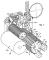
- the cutting device comprises a first roller 10 which in the area of their surface 10.1 with an axial Corrugation 12 is formed. This way, in Axial direction of the roller 10 extending ribs 12.1 and parallel to it between the ribs 12.1 Valleys 12.2 trained. This gives the roller 10 a fan-type design. When turning the roller 10 in the direction of the arrow D10 becomes air (cooling air) accordingly in the direction of one arranged behind it third roller, the cutting roller 30, promoted.
- roller 10 In addition to the first roller 10, there is a coaxial with the roller 10 arranged second roller 20, the surface 20.1 a Rubber covering.
- the roller 10 rolls with it Corrugation 12 on the surface 20.1 of the roller 20, which rotates accordingly in the direction of arrow D20.
- the cutting roller 30 Coaxial to the second roller 20 is behind the rollers 10, 20 the cutting roller 30 is arranged.
- the cutting roller 30 also has a profiled surface, similar the first roller 10.
- In the surface area of the Cutting roller 30 are trapezoidal recesses 32 too recognize that in the axial direction of the third roller 30 run. Lie in these recesses 32 corresponding roller pieces 34 whose surface the corrugation of the adjacent sections of the Continue cutting roller 30.
- the roller pieces 34 lie stationary in the recesses 32 and fix simultaneously in the axial direction of the cutting roller 30 running knife 36, which between corresponding Flanks of the roller pieces 34 and recesses 32 are fixed and the ribs 38 of the third roller 30 overtop.
- the cutting roller 30 is arranged so that its knife 36 (here: 14 knives) the surface 20.1 of the second Touch roller 20 or roll on it.
- fiber strands are initially are passed between the rollers 10, 20 their way between the rollers 20, 30 according to the Distance of the knives 36 in corresponding sections cut.
- Figure 2 also shows that in the axial direction of the rollers 10, 20, 30 via different pipelines 50 transported glass fiber strands 40 before their way through the cutter along a curved Path 52 of the pipes 50 are deflected.
- Figure 2 also shows - in schematic form - one spring-loaded mounting (spring 14) of the first roller 10 or the second roller 20 (cylinder 16).
Landscapes
- Chemical & Material Sciences (AREA)
- Engineering & Computer Science (AREA)
- Composite Materials (AREA)
- Mechanical Engineering (AREA)
- Reinforced Plastic Materials (AREA)
- Preliminary Treatment Of Fibers (AREA)
- Moulding By Coating Moulds (AREA)
- Processing And Handling Of Plastics And Other Materials For Molding In General (AREA)
- Rollers For Roller Conveyors For Transfer (AREA)
- Forwarding And Storing Of Filamentary Material (AREA)
- Vending Machines For Individual Products (AREA)
- Re-Forming, After-Treatment, Cutting And Transporting Of Glass Products (AREA)
- Treatment Of Fiber Materials (AREA)
- Valve Device For Special Equipments (AREA)
- Control Of Stepping Motors (AREA)
- Portable Nailing Machines And Staplers (AREA)
- Manufacture, Treatment Of Glass Fibers (AREA)
- Surgical Instruments (AREA)
- Electrical Discharge Machining, Electrochemical Machining, And Combined Machining (AREA)
- Vehicle Body Suspensions (AREA)
Claims (9)
- Bras d'alimentation pour le transport, le traitement et la sortie de différents matériaux de départ (40) pour la fabrication de tuyaux en plastique armés de fibres de verre présentant les caractéristiques suivantes :1.1 un dispositif de coupe disposé à l'extrémité côté sortie pour le découpage de fils en fibres de verre (40) à une longueur prédéfinie,1.2 le dispositif de coupe présente au moins trois cylindres (10, 20, 30) disposés parallèlement à l'axe les uns par rapport aux autres,1.3 un premier cylindre (10) est conçu avec une surface (10.1) profilée et est disposé de telle sorte que sa surface (10.1) se déroule sur un deuxième cylindre (20) tournant dans le sens contraire au premier cylindre (10),1.4 Un troisième cylindre (30) présente sur sa surface (30.1) une pluralité de couteaux (36) espacés dans le sens axial du cylindre (30) et est disposé de telle sorte que sa surface (30.1) se déroule sur le deuxième cylindre (20) tournant dans le sens contraire au troisième cylindre (30)
- Bras d'alimentation selon la revendication 1, dans lequel le deuxième cylindre (20) du dispositif de coupe présente une surface (20.1) déformable de façon réversible.
- Bras d'alimentation selon la revendication 2, dans lequel la surface (20.1) du deuxième cylindre (20) est réalisé dans un matériau à base de plastique ou de caoutchouc.
- Bras d'alimentation selon la revendication 1, dans lequel la surface (10.1) du premier cylindre est profilée par des nervures (12.1) allant dans le sens axial.
- Bras d'alimentation selon la revendication 1, dans lequel le premier cylindre (10) présente un diamètre plus petit que les deuxième et troisième cylindres (20, 30).
- Bras d'alimentation selon la revendication 1, dans lequel les couteaux (36) du troisième cylindre (30) sont ancrés dans le corps du cylindre (30) de façon amovible.
- Bras d'alimentation selon la revendication 1, dans lequel le troisième cylindre (30) est réalisé dans la zone située entre les couteaux (36) avec des nervures (38) agencées dans le sens axial.
- Bras d'alimentation selon la revendication 1, dans lequel le premier cylindre (10) est monté de façon élastique.
- Bras d'alimentation selon la revendication 1, dans lequel le deuxième cylindre (20) est monté de façon élastique.
Applications Claiming Priority (3)
| Application Number | Priority Date | Filing Date | Title |
|---|---|---|---|
| DE19912297 | 1999-03-19 | ||
| DE19912297A DE19912297C1 (de) | 1999-03-19 | 1999-03-19 | Beschickungsarm |
| PCT/EP2000/000649 WO2000056525A1 (fr) | 1999-03-19 | 2000-01-28 | Bras de chargement |
Publications (2)
| Publication Number | Publication Date |
|---|---|
| EP1082206A1 EP1082206A1 (fr) | 2001-03-14 |
| EP1082206B1 true EP1082206B1 (fr) | 2002-03-13 |
Family
ID=7901567
Family Applications (1)
| Application Number | Title | Priority Date | Filing Date |
|---|---|---|---|
| EP00907484A Expired - Lifetime EP1082206B1 (fr) | 1999-03-19 | 2000-01-28 | Bras de chargement |
Country Status (12)
| Country | Link |
|---|---|
| US (1) | US6892617B1 (fr) |
| EP (1) | EP1082206B1 (fr) |
| JP (1) | JP3497137B2 (fr) |
| CN (1) | CN1101309C (fr) |
| AT (1) | ATE214327T1 (fr) |
| AU (1) | AU735759B2 (fr) |
| CZ (1) | CZ294544B6 (fr) |
| DE (2) | DE19912297C1 (fr) |
| EA (1) | EA001999B1 (fr) |
| ES (1) | ES2171385T3 (fr) |
| PL (1) | PL192249B1 (fr) |
| WO (1) | WO2000056525A1 (fr) |
Families Citing this family (5)
| Publication number | Priority date | Publication date | Assignee | Title |
|---|---|---|---|---|
| DE102004016609B3 (de) * | 2004-04-03 | 2005-03-03 | Knoch, Kern & Co. | Zuführorgan und zugehörige Vorrichtung |
| US10201905B2 (en) * | 2009-05-19 | 2019-02-12 | Jerry R. Fram | Fiber cutting device |
| US9629390B1 (en) * | 2013-01-26 | 2017-04-25 | Turner Innovations Ltd. | Sorrel harvesting machine with spaced apart rotating return and cutting drums moving in opposite directions at a throat therebetween |
| CN104955578B (zh) * | 2013-01-31 | 2016-11-09 | 固瑞克明尼苏达有限公司 | 双楔形物夹子成角度刀片切割系统 |
| CN116854363B (zh) * | 2023-07-06 | 2026-04-14 | 五河县维佳复合材料有限公司 | 一种用于静电玻璃纤维短切丝用防飞尘短切机 |
Family Cites Families (18)
| Publication number | Priority date | Publication date | Assignee | Title |
|---|---|---|---|---|
| US2010078A (en) * | 1931-06-04 | 1935-08-06 | Celanese Corp | Production of staple fibers |
| US2974554A (en) * | 1954-01-02 | 1961-03-14 | Bayer Ag | Method of and apparatus for cutting staple lengths of cables of artificial threads |
| US3111875A (en) * | 1956-02-07 | 1963-11-26 | Takehara Kokuji | Fiber cutting device |
| US3045520A (en) * | 1961-10-02 | 1962-07-24 | Haruyama Ichizo | Apparatus for cutting chemical tows |
| US3763561A (en) * | 1972-02-22 | 1973-10-09 | Ransburg Electro Coating Corp | Fiber cutter |
| US3942401A (en) * | 1972-03-24 | 1976-03-09 | Saint-Gobain Industries | Method for cutting fibers |
| US3815461A (en) * | 1972-10-26 | 1974-06-11 | Johns Manville | Apparatus for chopping strand |
| US3869268A (en) * | 1973-12-11 | 1975-03-04 | Ppg Industries Inc | Method and apparatus for chopping fibers |
| FR2322836A1 (fr) * | 1975-09-04 | 1977-04-01 | Saint Gobain | Procede et dispositifs pour la coupe de fils de matiere minerale, notamment de fils de verre |
| US3992967A (en) * | 1975-10-31 | 1976-11-23 | Ransburg Corporation | Fiber cutter |
| US4191079A (en) * | 1978-08-25 | 1980-03-04 | Owens-Corning Fiberglas Corporation | Textile strand control device |
| JPS5942608B2 (ja) * | 1980-10-31 | 1984-10-16 | 日立造船株式会社 | 強化繊維内在台形樹脂管の遠心成形方法 |
| JPS5976224A (ja) * | 1982-10-22 | 1984-05-01 | Hitachi Chem Co Ltd | 繊維強化プラスチツクス管の成形方法および成形装置 |
| US4637286A (en) * | 1984-07-24 | 1987-01-20 | Allied Corporation | Staple cutting for fiber reinforcement material |
| US5253561A (en) * | 1991-10-10 | 1993-10-19 | Harry Wynn | Rotary butt cutting apparatus |
| JP2611720B2 (ja) * | 1993-02-22 | 1997-05-21 | 株式会社デンソー | 連続波状体の切断装置 |
| US5970837A (en) * | 1996-12-18 | 1999-10-26 | Johns Manville International, Inc. | Chopper for cutting fiber continuously, and method |
| US6202525B1 (en) * | 1998-02-25 | 2001-03-20 | Johns Manville International, Inc. | Chopping apparatus |
-
1999
- 1999-03-19 DE DE19912297A patent/DE19912297C1/de not_active Expired - Fee Related
-
2000
- 2000-01-28 WO PCT/EP2000/000649 patent/WO2000056525A1/fr not_active Ceased
- 2000-01-28 DE DE50000121T patent/DE50000121D1/de not_active Expired - Fee Related
- 2000-01-28 CZ CZ20004258A patent/CZ294544B6/cs not_active IP Right Cessation
- 2000-01-28 CN CN00800840A patent/CN1101309C/zh not_active Expired - Fee Related
- 2000-01-28 US US09/700,693 patent/US6892617B1/en not_active Expired - Fee Related
- 2000-01-28 JP JP2000606408A patent/JP3497137B2/ja not_active Expired - Fee Related
- 2000-01-28 AU AU29054/00A patent/AU735759B2/en not_active Ceased
- 2000-01-28 EA EA200001205A patent/EA001999B1/ru not_active IP Right Cessation
- 2000-01-28 ES ES00907484T patent/ES2171385T3/es not_active Expired - Lifetime
- 2000-01-28 PL PL344326A patent/PL192249B1/pl not_active IP Right Cessation
- 2000-01-28 AT AT00907484T patent/ATE214327T1/de not_active IP Right Cessation
- 2000-01-28 EP EP00907484A patent/EP1082206B1/fr not_active Expired - Lifetime
Also Published As
| Publication number | Publication date |
|---|---|
| JP3497137B2 (ja) | 2004-02-16 |
| CN1304354A (zh) | 2001-07-18 |
| PL344326A1 (en) | 2001-10-22 |
| EA200001205A1 (ru) | 2001-06-25 |
| AU2905400A (en) | 2000-10-09 |
| JP2002540030A (ja) | 2002-11-26 |
| CZ20004258A3 (en) | 2001-05-16 |
| EP1082206A1 (fr) | 2001-03-14 |
| CN1101309C (zh) | 2003-02-12 |
| DE19912297C1 (de) | 2000-06-29 |
| WO2000056525A1 (fr) | 2000-09-28 |
| US6892617B1 (en) | 2005-05-17 |
| CZ294544B6 (cs) | 2005-01-12 |
| ES2171385T3 (es) | 2002-09-16 |
| DE50000121D1 (de) | 2002-04-18 |
| AU735759B2 (en) | 2001-07-12 |
| PL192249B1 (pl) | 2006-09-29 |
| EA001999B1 (ru) | 2001-10-22 |
| ATE214327T1 (de) | 2002-03-15 |
Similar Documents
| Publication | Publication Date | Title |
|---|---|---|
| DE69003987T2 (de) | Fasertrenner für die Herstellung von faserverstärkten Körpern aus Kunstharz oder Metall. | |
| DE2248683C3 (de) | Vorrichtung zum Querschneiden einer kontinuierlich angeförderten Materialbahn | |
| DE102008016862C5 (de) | Extruder | |
| EP0979719A2 (fr) | Procédé et extrudeuse de plastification pour produire des compositions polymères renforcées par des fibres | |
| EP0667414B1 (fr) | Dispositif de raclage | |
| DE102009037126A1 (de) | Vorrichtung zum Reinigen einer Funktionsoberfläche zur Führung oder Behandlung einer Materialbahn | |
| CH434700A (de) | Granuliervorrichtung, insbesondere für thermoplastische Kunststoffe und Verfahren zu ihrem Betrieb | |
| DE60009918T2 (de) | Verfahren zur herstellung von getrennten faserlängen | |
| EP1543930B1 (fr) | Dispositif pour le traitment de caoutchouc | |
| EP1082206B1 (fr) | Bras de chargement | |
| DE69905521T2 (de) | Verfahren und Vorrichtung zum Herstellen von Garn aus themoplastischem geschnittenen Material | |
| EP3235388B1 (fr) | Dispositif d'application d'une bande de colle sur une bande d'enrobage en forme de tige de l'industrie de traitement du tabac | |
| EP3280664B1 (fr) | Dispositif servant à réduire le nombre de filaments d'un renforcement à base de fibres | |
| DE69313957T2 (de) | Vorrichtung zum Kräuseln eines Faserstranges und zum Aufbringen von Finish auf den Faserstrang | |
| DE102019107664B4 (de) | Verfahren und Vorrichtung zur additiven Herstellung von hochfesten Bauteilen | |
| EP2024149B1 (fr) | Dispositif pour l'estampage rotatif de pièces découpées de géométrie et de taille définies constitué d'une structure plate et son utilisation | |
| DE60318956T2 (de) | Verfahren und vorrichtung zum auftragen einer beschichtigung auf einen um eine achse rotierenden körper | |
| EP2225161B1 (fr) | Utilisation d'un dispositif de coupe dans un dispositif d'étiquetage | |
| DE2359368A1 (de) | Verfahren und vorrichtung zur herstellung von verstaerkungselementen kurzer laengenausdehnung | |
| DE2638751A1 (de) | Vorrichtung zur herstellung von stahlfasern | |
| EP3966139B1 (fr) | Procédé et dispositif de nettoyage d'une surface d'une bande transporteuse en vue d'éliminer des résidus de matières premières transportées pour l'industrie minière et des déblais | |
| EP2017206B1 (fr) | Dispositif pour la fabrication d' un voile non-tissé spunbond | |
| EP2729025A1 (fr) | Système de transport longitudinal destiné à des produits de l'industrie du tabac | |
| DE102018002473A1 (de) | Mischvorrichtung für Fasern oder Späne und Bindemittel | |
| CH715687A2 (de) | Mischvorrichtung, insbesondere zur Kautschukverarbeitung, sowie ein Verfahren zu deren Betrieb. |
Legal Events
| Date | Code | Title | Description |
|---|---|---|---|
| PUAI | Public reference made under article 153(3) epc to a published international application that has entered the european phase |
Free format text: ORIGINAL CODE: 0009012 |
|
| 17P | Request for examination filed |
Effective date: 20001123 |
|
| AK | Designated contracting states |
Kind code of ref document: A1 Designated state(s): AT BE CH CY DE DK ES FI FR GB GR IE IT LI LU MC NL PT SE |
|
| AX | Request for extension of the european patent |
Free format text: RO PAYMENT 20001123 |
|
| GRAG | Despatch of communication of intention to grant |
Free format text: ORIGINAL CODE: EPIDOS AGRA |
|
| GRAG | Despatch of communication of intention to grant |
Free format text: ORIGINAL CODE: EPIDOS AGRA |
|
| GRAH | Despatch of communication of intention to grant a patent |
Free format text: ORIGINAL CODE: EPIDOS IGRA |
|
| 17Q | First examination report despatched |
Effective date: 20010828 |
|
| GRAH | Despatch of communication of intention to grant a patent |
Free format text: ORIGINAL CODE: EPIDOS IGRA |
|
| REG | Reference to a national code |
Ref country code: GB Ref legal event code: IF02 |
|
| GRAA | (expected) grant |
Free format text: ORIGINAL CODE: 0009210 |
|
| AK | Designated contracting states |
Kind code of ref document: B1 Designated state(s): AT BE CH CY DE DK ES FI FR GB GR IE IT LI LU MC NL PT SE |
|
| AX | Request for extension of the european patent |
Free format text: RO PAYMENT 20001123 |
|
| PG25 | Lapsed in a contracting state [announced via postgrant information from national office to epo] |
Ref country code: FI Free format text: LAPSE BECAUSE OF FAILURE TO SUBMIT A TRANSLATION OF THE DESCRIPTION OR TO PAY THE FEE WITHIN THE PRESCRIBED TIME-LIMIT Effective date: 20020313 Ref country code: NL Free format text: LAPSE BECAUSE OF FAILURE TO SUBMIT A TRANSLATION OF THE DESCRIPTION OR TO PAY THE FEE WITHIN THE PRESCRIBED TIME-LIMIT Effective date: 20020313 Ref country code: IE Free format text: LAPSE BECAUSE OF FAILURE TO SUBMIT A TRANSLATION OF THE DESCRIPTION OR TO PAY THE FEE WITHIN THE PRESCRIBED TIME-LIMIT Effective date: 20020313 Ref country code: GR Free format text: LAPSE BECAUSE OF FAILURE TO SUBMIT A TRANSLATION OF THE DESCRIPTION OR TO PAY THE FEE WITHIN THE PRESCRIBED TIME-LIMIT Effective date: 20020313 |
|
| REF | Corresponds to: |
Ref document number: 214327 Country of ref document: AT Date of ref document: 20020315 Kind code of ref document: T |
|
| REG | Reference to a national code |
Ref country code: CH Ref legal event code: EP |
|
| REF | Corresponds to: |
Ref document number: 50000121 Country of ref document: DE Date of ref document: 20020418 |
|
| REG | Reference to a national code |
Ref country code: CH Ref legal event code: NV Representative=s name: HANS RUDOLF GACHNANG PATENTANWALT |
|
| PG25 | Lapsed in a contracting state [announced via postgrant information from national office to epo] |
Ref country code: DK Free format text: LAPSE BECAUSE OF FAILURE TO SUBMIT A TRANSLATION OF THE DESCRIPTION OR TO PAY THE FEE WITHIN THE PRESCRIBED TIME-LIMIT Effective date: 20020613 |
|
| PG25 | Lapsed in a contracting state [announced via postgrant information from national office to epo] |
Ref country code: PT Free format text: LAPSE BECAUSE OF FAILURE TO SUBMIT A TRANSLATION OF THE DESCRIPTION OR TO PAY THE FEE WITHIN THE PRESCRIBED TIME-LIMIT Effective date: 20020614 |
|
| NLV1 | Nl: lapsed or annulled due to failure to fulfill the requirements of art. 29p and 29m of the patents act | ||
| ET | Fr: translation filed | ||
| REG | Reference to a national code |
Ref country code: ES Ref legal event code: FG2A Ref document number: 2171385 Country of ref document: ES Kind code of ref document: T3 |
|
| REG | Reference to a national code |
Ref country code: IE Ref legal event code: FD4D |
|
| PLBE | No opposition filed within time limit |
Free format text: ORIGINAL CODE: 0009261 |
|
| STAA | Information on the status of an ep patent application or granted ep patent |
Free format text: STATUS: NO OPPOSITION FILED WITHIN TIME LIMIT |
|
| PG25 | Lapsed in a contracting state [announced via postgrant information from national office to epo] |
Ref country code: LU Free format text: LAPSE BECAUSE OF NON-PAYMENT OF DUE FEES Effective date: 20030128 Ref country code: CY Free format text: LAPSE BECAUSE OF FAILURE TO SUBMIT A TRANSLATION OF THE DESCRIPTION OR TO PAY THE FEE WITHIN THE PRESCRIBED TIME-LIMIT Effective date: 20030128 |
|
| PG25 | Lapsed in a contracting state [announced via postgrant information from national office to epo] |
Ref country code: MC Free format text: LAPSE BECAUSE OF NON-PAYMENT OF DUE FEES Effective date: 20030131 |
|
| 26N | No opposition filed |
Effective date: 20021216 |
|
| PGFP | Annual fee paid to national office [announced via postgrant information from national office to epo] |
Ref country code: GB Payment date: 20040107 Year of fee payment: 5 |
|
| PGFP | Annual fee paid to national office [announced via postgrant information from national office to epo] |
Ref country code: FR Payment date: 20040120 Year of fee payment: 5 |
|
| PGFP | Annual fee paid to national office [announced via postgrant information from national office to epo] |
Ref country code: AT Payment date: 20040123 Year of fee payment: 5 |
|
| PGFP | Annual fee paid to national office [announced via postgrant information from national office to epo] |
Ref country code: SE Payment date: 20040126 Year of fee payment: 5 |
|
| PGFP | Annual fee paid to national office [announced via postgrant information from national office to epo] |
Ref country code: BE Payment date: 20040127 Year of fee payment: 5 |
|
| PG25 | Lapsed in a contracting state [announced via postgrant information from national office to epo] |
Ref country code: LI Free format text: LAPSE BECAUSE OF NON-PAYMENT OF DUE FEES Effective date: 20040131 Ref country code: CH Free format text: LAPSE BECAUSE OF NON-PAYMENT OF DUE FEES Effective date: 20040131 |
|
| REG | Reference to a national code |
Ref country code: CH Ref legal event code: PL |
|
| PG25 | Lapsed in a contracting state [announced via postgrant information from national office to epo] |
Ref country code: AT Free format text: LAPSE BECAUSE OF NON-PAYMENT OF DUE FEES Effective date: 20050128 Ref country code: GB Free format text: LAPSE BECAUSE OF NON-PAYMENT OF DUE FEES Effective date: 20050128 |
|
| PG25 | Lapsed in a contracting state [announced via postgrant information from national office to epo] |
Ref country code: SE Free format text: LAPSE BECAUSE OF NON-PAYMENT OF DUE FEES Effective date: 20050129 |
|
| PG25 | Lapsed in a contracting state [announced via postgrant information from national office to epo] |
Ref country code: BE Free format text: LAPSE BECAUSE OF NON-PAYMENT OF DUE FEES Effective date: 20050131 |
|
| BERE | Be: lapsed |
Owner name: *HOBAS ENGINEERING G.M.B.H. Effective date: 20050131 |
|
| EUG | Se: european patent has lapsed | ||
| GBPC | Gb: european patent ceased through non-payment of renewal fee |
Effective date: 20050128 |
|
| PG25 | Lapsed in a contracting state [announced via postgrant information from national office to epo] |
Ref country code: FR Free format text: LAPSE BECAUSE OF NON-PAYMENT OF DUE FEES Effective date: 20050930 |
|
| REG | Reference to a national code |
Ref country code: FR Ref legal event code: ST |
|
| PGFP | Annual fee paid to national office [announced via postgrant information from national office to epo] |
Ref country code: ES Payment date: 20070125 Year of fee payment: 8 |
|
| PGFP | Annual fee paid to national office [announced via postgrant information from national office to epo] |
Ref country code: DE Payment date: 20070127 Year of fee payment: 8 |
|
| BERE | Be: lapsed |
Owner name: *HOBAS ENGINEERING G.M.B.H. Effective date: 20050131 |
|
| PGFP | Annual fee paid to national office [announced via postgrant information from national office to epo] |
Ref country code: IT Payment date: 20070531 Year of fee payment: 8 |
|
| PG25 | Lapsed in a contracting state [announced via postgrant information from national office to epo] |
Ref country code: DE Free format text: LAPSE BECAUSE OF NON-PAYMENT OF DUE FEES Effective date: 20080801 |
|
| REG | Reference to a national code |
Ref country code: ES Ref legal event code: FD2A Effective date: 20080129 |
|
| PG25 | Lapsed in a contracting state [announced via postgrant information from national office to epo] |
Ref country code: ES Free format text: LAPSE BECAUSE OF NON-PAYMENT OF DUE FEES Effective date: 20080129 |
|
| PG25 | Lapsed in a contracting state [announced via postgrant information from national office to epo] |
Ref country code: IT Free format text: LAPSE BECAUSE OF NON-PAYMENT OF DUE FEES Effective date: 20080128 |