EP1083254A2 - Pull cord for blinds and method of making same - Google Patents
Pull cord for blinds and method of making same Download PDFInfo
- Publication number
- EP1083254A2 EP1083254A2 EP00307726A EP00307726A EP1083254A2 EP 1083254 A2 EP1083254 A2 EP 1083254A2 EP 00307726 A EP00307726 A EP 00307726A EP 00307726 A EP00307726 A EP 00307726A EP 1083254 A2 EP1083254 A2 EP 1083254A2
- Authority
- EP
- European Patent Office
- Prior art keywords
- cord
- yarn
- bobbins
- urethane
- braided
- Prior art date
- Legal status (The legal status is an assumption and is not a legal conclusion. Google has not performed a legal analysis and makes no representation as to the accuracy of the status listed.)
- Withdrawn
Links
- 238000004519 manufacturing process Methods 0.000 title claims abstract description 5
- JOYRKODLDBILNP-UHFFFAOYSA-N Ethyl urethane Chemical compound CCOC(N)=O JOYRKODLDBILNP-UHFFFAOYSA-N 0.000 claims abstract description 26
- 238000000576 coating method Methods 0.000 claims abstract description 16
- 239000011248 coating agent Substances 0.000 claims abstract description 15
- 238000005299 abrasion Methods 0.000 claims abstract description 8
- 238000009954 braiding Methods 0.000 claims abstract description 8
- 238000000034 method Methods 0.000 claims description 12
- XLYOFNOQVPJJNP-UHFFFAOYSA-N water Substances O XLYOFNOQVPJJNP-UHFFFAOYSA-N 0.000 claims description 3
- 239000000203 mixture Substances 0.000 claims description 2
- 238000004804 winding Methods 0.000 abstract 1
- 239000000835 fiber Substances 0.000 description 12
- 238000001723 curing Methods 0.000 description 4
- 238000010438 heat treatment Methods 0.000 description 4
- 239000004698 Polyethylene Substances 0.000 description 3
- -1 polyethylene Polymers 0.000 description 3
- 229920000573 polyethylene Polymers 0.000 description 3
- 238000010586 diagram Methods 0.000 description 2
- 238000001035 drying Methods 0.000 description 2
- 239000004033 plastic Substances 0.000 description 2
- 229920003023 plastic Polymers 0.000 description 2
- 229920000728 polyester Polymers 0.000 description 2
- 229920000271 Kevlar® Polymers 0.000 description 1
- 229920000784 Nomex Polymers 0.000 description 1
- 239000004721 Polyphenylene oxide Substances 0.000 description 1
- 229920006362 Teflon® Polymers 0.000 description 1
- 229920000561 Twaron Polymers 0.000 description 1
- HCHKCACWOHOZIP-UHFFFAOYSA-N Zinc Chemical compound [Zn] HCHKCACWOHOZIP-UHFFFAOYSA-N 0.000 description 1
- 239000000919 ceramic Substances 0.000 description 1
- 230000006866 deterioration Effects 0.000 description 1
- 230000002542 deteriorative effect Effects 0.000 description 1
- 239000006185 dispersion Substances 0.000 description 1
- 239000002783 friction material Substances 0.000 description 1
- 238000013007 heat curing Methods 0.000 description 1
- 238000009998 heat setting Methods 0.000 description 1
- 239000004761 kevlar Substances 0.000 description 1
- 239000004763 nomex Substances 0.000 description 1
- 229920000570 polyether Polymers 0.000 description 1
- 229920003009 polyurethane dispersion Polymers 0.000 description 1
- 230000000717 retained effect Effects 0.000 description 1
- 238000001228 spectrum Methods 0.000 description 1
- 239000000126 substance Substances 0.000 description 1
- 239000004762 twaron Substances 0.000 description 1
- 229920000785 ultra high molecular weight polyethylene Polymers 0.000 description 1
- 238000011144 upstream manufacturing Methods 0.000 description 1
- 239000011701 zinc Substances 0.000 description 1
- 229910052725 zinc Inorganic materials 0.000 description 1
Images


Classifications
-
- D—TEXTILES; PAPER
- D07—ROPES; CABLES OTHER THAN ELECTRIC
- D07B—ROPES OR CABLES IN GENERAL
- D07B7/00—Details of, or auxiliary devices incorporated in, rope- or cable-making machines; Auxiliary apparatus associated with such machines
- D07B7/02—Machine details; Auxiliary devices
- D07B7/14—Machine details; Auxiliary devices for coating or wrapping ropes, cables, or component strands thereof
- D07B7/145—Coating or filling-up interstices
-
- D—TEXTILES; PAPER
- D04—BRAIDING; LACE-MAKING; KNITTING; TRIMMINGS; NON-WOVEN FABRICS
- D04C—BRAIDING OR MANUFACTURE OF LACE, INCLUDING BOBBIN-NET OR CARBONISED LACE; BRAIDING MACHINES; BRAID; LACE
- D04C1/00—Braid or lace, e.g. pillow-lace; Processes for the manufacture thereof
- D04C1/06—Braid or lace serving particular purposes
- D04C1/12—Cords, lines, or tows
-
- D—TEXTILES; PAPER
- D07—ROPES; CABLES OTHER THAN ELECTRIC
- D07B—ROPES OR CABLES IN GENERAL
- D07B1/00—Constructional features of ropes or cables
- D07B1/02—Ropes built-up from fibrous or filamentary material, e.g. of vegetable origin, of animal origin, regenerated cellulose, plastics
-
- D—TEXTILES; PAPER
- D07—ROPES; CABLES OTHER THAN ELECTRIC
- D07B—ROPES OR CABLES IN GENERAL
- D07B1/00—Constructional features of ropes or cables
- D07B1/16—Ropes or cables with an enveloping sheathing or inlays of rubber or plastics
-
- D—TEXTILES; PAPER
- D07—ROPES; CABLES OTHER THAN ELECTRIC
- D07B—ROPES OR CABLES IN GENERAL
- D07B1/00—Constructional features of ropes or cables
- D07B1/16—Ropes or cables with an enveloping sheathing or inlays of rubber or plastics
- D07B1/162—Ropes or cables with an enveloping sheathing or inlays of rubber or plastics characterised by a plastic or rubber enveloping sheathing
-
- D—TEXTILES; PAPER
- D07—ROPES; CABLES OTHER THAN ELECTRIC
- D07B—ROPES OR CABLES IN GENERAL
- D07B5/00—Making ropes or cables from special materials or of particular form
-
- D—TEXTILES; PAPER
- D07—ROPES; CABLES OTHER THAN ELECTRIC
- D07B—ROPES OR CABLES IN GENERAL
- D07B2201/00—Ropes or cables
- D07B2201/10—Rope or cable structures
- D07B2201/1096—Rope or cable structures braided
-
- D—TEXTILES; PAPER
- D07—ROPES; CABLES OTHER THAN ELECTRIC
- D07B—ROPES OR CABLES IN GENERAL
- D07B2201/00—Ropes or cables
- D07B2201/20—Rope or cable components
- D07B2201/2083—Jackets or coverings
- D07B2201/2087—Jackets or coverings being of the coated type
-
- D—TEXTILES; PAPER
- D07—ROPES; CABLES OTHER THAN ELECTRIC
- D07B—ROPES OR CABLES IN GENERAL
- D07B2205/00—Rope or cable materials
- D07B2205/20—Organic high polymers
- D07B2205/2064—Polyurethane resins
-
- D—TEXTILES; PAPER
- D07—ROPES; CABLES OTHER THAN ELECTRIC
- D07B—ROPES OR CABLES IN GENERAL
- D07B2207/00—Rope or cable making machines
- D07B2207/40—Machine components
- D07B2207/404—Heat treating devices; Corresponding methods
-
- D—TEXTILES; PAPER
- D07—ROPES; CABLES OTHER THAN ELECTRIC
- D07B—ROPES OR CABLES IN GENERAL
- D07B2501/00—Application field
- D07B2501/20—Application field related to ropes or cables
- D07B2501/2084—Mechanical controls, e.g. door lashes
Definitions
- the present invention relates generally to pull cords used in coverings for architectural openings and more particularly to a braided pull cord and the method of making the cord.
- the control cord or the like typically depends from one end of a headrail for the covering and extends into the headrail through a friction brake and subsequently through carrier elements and around a plurality of pulleys and the like that are associated with the operation of the covering.
- the control cord is frictionally engaged at a number of locations and, depending upon the frequency of operation of the covering and the abrasiveness of the elements with which the cord comes into contact, the control elements can easily deteriorate.
- a typical fiber based cord used in coverings for architectural openings is braided from polyester fibers, with the cords typically including sixteen carrier fibers. After braiding of the cord, it is heat treated and wound on storage rolls before being incorporated into a covering product. The braid is relatively tight.
- the cord of the present invention is made from high tensile strength fibers with low abrasion characteristics, such as polyethylene fibers.
- the fibers are braided in an eight-carrier braid that is wound under very high tension and ultimately finished with a urethane coating that is heat cured.
- the resultant product has provided a wear cycle of many times that achieved with state-of-the-art cords thereby almost removing the problem of manufacturers in having to record coverings for architectural openings.
- high tensile strength fibers with low abrasion such as might be polyethylene fibers, are wound under high tension onto yarn bobbins and eight of the yarn bobbins are then utilized in a conventional braiding apparatus to braid the cord.
- the braided cord is held under tension and passed through a two-stage heat setting process wherein a urethane coating is applied to the braided cord and the coating is heat cured in the final stage. After the second stage of heating, the cord is wound onto spools for storage until they are strung into coverings for architectural openings.
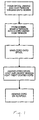
- Fig. 1 is a block diagram illustrating the steps in the process of making the cord in accordance with the present invention.
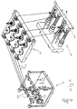
- Fig. 2 is a fragmentary diagrammatic isometric view showing yarn from which the cord will be braided being passed from supply spools under tension to bobbins.
- Fig. 3 is a fragmentary isometric illustrating the bobbins carrying the yarns under tension and being positioned in a braiding apparatus and with the braided cord being wrapped on a storage spool.
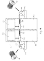
- Fig. 4 is a diagrammatic view showing yarn from storage spools being passed through a two-stage process for coating the yarns with urethane and heat curing the urethane on the yarn before accumulating the yarns on storage spools.
- Fig. 5 is a fragmentary elevation showing the braided cord in accordance with the present invention.
- Fig. 6 is a diagrammatic elevation showing a prior art braided cord.
- a braided control cord for use in coverings for architectural openings in accordance with the present invention is illustrated in a block diagram in Fig. 1. It will there be appreciated that fibers or yarns from which the cord is to be braided are first unwound from spools on which they are supplied and then wound under high tension onto bobbins. From the bobbins, eight yarns are braided into a cord also under high tension and the braided cord is subsequently wound on a transfer spool.
- the cords are unwound from the transfer spools under tension and fed into a treating apparatus where they are coated with urethane and immediately heat cured in a two-stage process so that the urethane coating is dried and fully cured on the braided cords. After the coating has been heat cured, the yarn is stored on storage spools from which it can be removed when incorporating the cord into an operating mechanism for a covering for architectural openings.
- a device 10 for unwinding yarn 12 from preformed spools 14 of yarn is shown in series with a conventional tensioning apparatus 16 for the yarns and a conventional apparatus 18 for wrapping the yarns on bobbins 20 under tension.
- the yarns are passed through an additional but conventional washer tensioner 21 before they are received by the tensioning apparatus 16.
- the device 10 for unwinding the yarn from the spools 14 can be seen to include a plurality of spindles 22 on which the spools 12 of yarn are disposed and the yarn is threaded through low friction ceramic guides 24 associated with each spool so that they can be passed individually to the washer tensioner 21 before passing on to the tensioning apparatus 16.
- the tensioning apparatus In the tensioning apparatus, they are tensioned in a conventional manner with washer tensioners 25 so that the yarns 12 when passed down to the bobbins 20 are fed to and wound on the bobbins under tension.
- Each of the devices and apparatuses 10, 16 and 18 are conventional items such as manufactured by Ratera of Spain.
- the yarns 12 have a high tensile strength in the range of 28-35 grams/denier, and preferably 30 grams/denier, and have low coefficients of friction, low abrasion characteristics and are durable from a flex fatigue standpoint.
- Examples of yarns that would be suitable for this purpose are Kevlar manufactured by DuPont in the United States, Nomex manufactured by DuPont, Twaron manufactured byAkzo of The Netherlands, Dyneema manufactured by DSM of Holland or Spectra manufactured by the Allied Signal Division of Honeywell, Inc., Orlando, Virginia.
- the yarn or fibers are preferably polyethylene.
- the tension under which the yarns 12 are wound on the bobbins 20 is preferably in the range of 115 to 140 grams and desirably 120 grams.
- the bobbins 20 with the yarn 12 wound thereon under tension are placed in a braiding apparatus 26 of a conventional type such as of the type manufactured by Ratera of Spain.
- a braiding apparatus 26 of a conventional type such as of the type manufactured by Ratera of Spain.
- eight yarns are braided into a cord 27 and after braiding, wound onto a transfer spool 28.
- the denier of the yarns is preferably in the range of 275 to 375, which is greater than the denier of yarns typically braided into control cords, as can be evidenced by reference to Figs. 5 and 6, with Fig. 5 being a cord braided in accordance with the present invention and Fig. 6 a prior art braided cord.
- the transfer rolls of braided cord are then operatively connected to a treatment apparatus 30 (Fig. 4) for final treatment of the cord.
- a treatment apparatus 30 Fig. 4
- Each transfer spool 28 of cord is rotatably mounted on a bracket 33 on the upstream end of the apparatus 30 so that the cord can be fed into and through the treatment apparatus under tension via a conventional tensioner 34.
- the tension in the cord is preferably in the range of 150-200g, with 150 grams being ideal.
- the braided cord 27 is first fed through a chamber 36 where the cord is padded with a urethane coating that is applied to the cord.
- the chamber 36 is fed from a urethane reservoir 37.
- the coating might be either sprayed onto the cord or the cord might be drawn through a bath of the urethane in order to apply the desired coating to the cord.
- the latter is preferred.
- the cord is coated with the urethane, it is passed through a heating chamber or oven 38 where the urethane is dried.
- the temperature in the heating chamber 38 is preferably in the range of 120-140°C even though temperatures outside that range would work as it would primarily affect the drying time.
- the cord is passed through another heating chamber 39 where the urethane is cured.
- the temperature in the curing chamber 39 is preferably in the range of 100-120°C even though, again, temperatures outside that range would work as the temperature primarily affects the curing time.
- the total time for drying and curing should ideally be in the range of 60-120 seconds, with 90 seconds being desired.
- the final braided cord is wrapped onto a storage spool 40 that is rotatably mounted on brackets 42 at the downstream end of the apparatus 34.
- a predetermined supply of the braided cord 27 is wound onto the storage spool 40, the spool is removed and retained for later use in the assembly of a covering for an architectural opening.
- the apparatus 30 for treating the cord with a urethane solution and curing the cord is conventional and may be of the type manufactured by Andersson Mek of Sweden.
- the urethane solution is a mixture of urethane and water in a concentration of 10% urethane by volume.
- the urethane is miscible in/with water and preferably itself comes from the chemical family of polyester, polyether polyurethane dispersions and can come from various sources but a urethane marketed under the designation Baypret DLV Dispersion Corporation by Bayer Corporation of Pittsburgh, Pennsylvania, has been found suitable for the cord of the present invention.
- a cord formed in accordance with the present invention and as illustrated in Fig. 5, has been found to provide a wear cycle that is approximately ten times that of conventional cords that are presently in use.
Landscapes
- Engineering & Computer Science (AREA)
- Manufacturing & Machinery (AREA)
- Textile Engineering (AREA)
- Ropes Or Cables (AREA)
- Braiding, Manufacturing Of Bobbin-Net Or Lace, And Manufacturing Of Nets By Knotting (AREA)
- Treatments For Attaching Organic Compounds To Fibrous Goods (AREA)
- Blinds (AREA)
Abstract
Description
- The present invention relates generally to pull cords used in coverings for architectural openings and more particularly to a braided pull cord and the method of making the cord.
- Most coverings for architectural openings, such as windows, doors, archways and the like, have an operating mechanism that is controlled by a flexible element that can be a fiber based cord, a beaded chain or the like. The control cord or the like typically depends from one end of a headrail for the covering and extends into the headrail through a friction brake and subsequently through carrier elements and around a plurality of pulleys and the like that are associated with the operation of the covering. As a result, the control cord is frictionally engaged at a number of locations and, depending upon the frequency of operation of the covering and the abrasiveness of the elements with which the cord comes into contact, the control elements can easily deteriorate.
- In the case of fiber based cords, the abrasion caused by the various elements in which it comes into contact, causes rapid deterioration of the cords. Cords that have deteriorated have to be replaced and many operating cords in coverings for architectural openings are replaced on an annual basis. When the covering has been warranted, the replacement cost is borne by the manufacturer and, accordingly, the quality and longevity of control cords is a significant economic factor in the covering industry.
- A typical fiber based cord used in coverings for architectural openings is braided from polyester fibers, with the cords typically including sixteen carrier fibers. After braiding of the cord, it is heat treated and wound on storage rolls before being incorporated into a covering product. The braid is relatively tight.
- In trying to resolve the problem of rapidly deteriorating operating cords, applicants initially looked to the hardware of the system to remove any abrasive surfaces across which the cord had to pass. By redesigning various plastic molded parts and the parting lines in the plastic molds for the parts, the wear cycle was improved. The redesigned components were later coated with low friction materials such as Teflon® or zinc to reduce abrasion, but only marginal improvement was noticed. Further, the coatings tended to wear off over time and with exposure to UV light. Applicants then decided that the focus for improving the wear cycle of operating cords needed to be on the cord itself and it is to this end that the present invention has been made.
- The cord of the present invention is made from high tensile strength fibers with low abrasion characteristics, such as polyethylene fibers. The fibers are braided in an eight-carrier braid that is wound under very high tension and ultimately finished with a urethane coating that is heat cured. The resultant product has provided a wear cycle of many times that achieved with state-of-the-art cords thereby almost removing the problem of manufacturers in having to record coverings for architectural openings. In accordance with the method for making the eight-carrier braid, high tensile strength fibers with low abrasion, such as might be polyethylene fibers, are wound under high tension onto yarn bobbins and eight of the yarn bobbins are then utilized in a conventional braiding apparatus to braid the cord. The braided cord is held under tension and passed through a two-stage heat setting process wherein a urethane coating is applied to the braided cord and the coating is heat cured in the final stage. After the second stage of heating, the cord is wound onto spools for storage until they are strung into coverings for architectural openings.
- Other aspects, features and details of the present invention can be more completely understood by reference to the following detailed description of a preferred embodiment, taken in conjunction with the drawings and from the appended claims.
- Fig. 1 is a block diagram illustrating the steps in the process of making the cord in accordance with the present invention.
- Fig. 2 is a fragmentary diagrammatic isometric view showing yarn from which the cord will be braided being passed from supply spools under tension to bobbins.
- Fig. 3 is a fragmentary isometric illustrating the bobbins carrying the yarns under tension and being positioned in a braiding apparatus and with the braided cord being wrapped on a storage spool.
- Fig. 4 is a diagrammatic view showing yarn from storage spools being passed through a two-stage process for coating the yarns with urethane and heat curing the urethane on the yarn before accumulating the yarns on storage spools.
- Fig. 5 is a fragmentary elevation showing the braided cord in accordance with the present invention.
- Fig. 6 is a diagrammatic elevation showing a prior art braided cord.
- The method of making a braided control cord for use in coverings for architectural openings in accordance with the present invention is illustrated in a block diagram in Fig. 1. It will there be appreciated that fibers or yarns from which the cord is to be braided are first unwound from spools on which they are supplied and then wound under high tension onto bobbins. From the bobbins, eight yarns are braided into a cord also under high tension and the braided cord is subsequently wound on a transfer spool. The cords are unwound from the transfer spools under tension and fed into a treating apparatus where they are coated with urethane and immediately heat cured in a two-stage process so that the urethane coating is dried and fully cured on the braided cords. After the coating has been heat cured, the yarn is stored on storage spools from which it can be removed when incorporating the cord into an operating mechanism for a covering for architectural openings.
- With reference to Fig. 2, a
device 10 forunwinding yarn 12 from preformed spools 14 of yarn is shown in series with aconventional tensioning apparatus 16 for the yarns and a conventional apparatus 18 for wrapping the yarns onbobbins 20 under tension. To provide even greater tension in the yarn than is provided by theconventional tensioning apparatus 16, the yarns are passed through an additional but conventional washer tensioner 21 before they are received by thetensioning apparatus 16. Thedevice 10 for unwinding the yarn from the spools 14 can be seen to include a plurality of spindles 22 on which thespools 12 of yarn are disposed and the yarn is threaded through low friction ceramic guides 24 associated with each spool so that they can be passed individually to the washer tensioner 21 before passing on to thetensioning apparatus 16. In the tensioning apparatus, they are tensioned in a conventional manner with washer tensioners 25 so that theyarns 12 when passed down to thebobbins 20 are fed to and wound on the bobbins under tension. Each of the devices andapparatuses - The
yarns 12 have a high tensile strength in the range of 28-35 grams/denier, and preferably 30 grams/denier, and have low coefficients of friction, low abrasion characteristics and are durable from a flex fatigue standpoint. Examples of yarns that would be suitable for this purpose are Kevlar manufactured by DuPont in the United States, Nomex manufactured by DuPont, Twaron manufactured byAkzo of The Netherlands, Dyneema manufactured by DSM of Holland or Spectra manufactured by the Allied Signal Division of Honeywell, Inc., Petersburg, Virginia. The yarn or fibers are preferably polyethylene. The tension under which theyarns 12 are wound on thebobbins 20 is preferably in the range of 115 to 140 grams and desirably 120 grams. - Looking next at Fig. 3, the
bobbins 20 with theyarn 12 wound thereon under tension, are placed in a braiding apparatus 26 of a conventional type such as of the type manufactured by Ratera of Spain. In the preferred embodiment of the invention, eight yarns are braided into acord 27 and after braiding, wound onto atransfer spool 28. The denier of the yarns is preferably in the range of 275 to 375, which is greater than the denier of yarns typically braided into control cords, as can be evidenced by reference to Figs. 5 and 6, with Fig. 5 being a cord braided in accordance with the present invention and Fig. 6 a prior art braided cord. - The transfer rolls of braided cord are then operatively connected to a treatment apparatus 30 (Fig. 4) for final treatment of the cord. Each
transfer spool 28 of cord is rotatably mounted on a bracket 33 on the upstream end of theapparatus 30 so that the cord can be fed into and through the treatment apparatus under tension via aconventional tensioner 34. The tension in the cord is preferably in the range of 150-200g, with 150 grams being ideal. In the apparatus, 30 thebraided cord 27 is first fed through achamber 36 where the cord is padded with a urethane coating that is applied to the cord. Thechamber 36 is fed from aurethane reservoir 37. By way of example, the coating might be either sprayed onto the cord or the cord might be drawn through a bath of the urethane in order to apply the desired coating to the cord. The latter is preferred. Immediately after the cord is coated with the urethane, it is passed through a heating chamber oroven 38 where the urethane is dried. The temperature in theheating chamber 38 is preferably in the range of 120-140°C even though temperatures outside that range would work as it would primarily affect the drying time. Subsequent thereto, the cord is passed through another heating chamber 39 where the urethane is cured. The temperature in the curing chamber 39 is preferably in the range of 100-120°C even though, again, temperatures outside that range would work as the temperature primarily affects the curing time. The total time for drying and curing should ideally be in the range of 60-120 seconds, with 90 seconds being desired. After thecord 27 has been padded with the urethane coating and cured, the final braided cord is wrapped onto astorage spool 40 that is rotatably mounted onbrackets 42 at the downstream end of theapparatus 34. When a predetermined supply of the braidedcord 27 is wound onto thestorage spool 40, the spool is removed and retained for later use in the assembly of a covering for an architectural opening. Theapparatus 30 for treating the cord with a urethane solution and curing the cord is conventional and may be of the type manufactured by Andersson Mek of Sweden. The urethane solution is a mixture of urethane and water in a concentration of 10% urethane by volume. The urethane is miscible in/with water and preferably itself comes from the chemical family of polyester, polyether polyurethane dispersions and can come from various sources but a urethane marketed under the designation Baypret DLV Dispersion Corporation by Bayer Corporation of Pittsburgh, Pennsylvania, has been found suitable for the cord of the present invention. - A cord formed in accordance with the present invention and as illustrated in Fig. 5, has been found to provide a wear cycle that is approximately ten times that of conventional cords that are presently in use.
- Although the present invention has been described with a certain degree of particularity, it is understood that the present disclosure has been made by way of example, and changes in detail or structure may be made without departing from the spirit of the invention as defined in the appended claims.
Claims (9)
- A method of making a control cord for use in coverings for architectural openings comprising the steps of:providing a spool of high tensile strength yarn with the yarn havinglow abrasion characteristics,removing the yarn from the spool and passing it through a tensioning device,wrapping the yarn under tension on bobbins,placing the bobbins in a braiding apparatus from which an eight-carrier braid is made, andpassing the braided cord through a treatment apparatus where a coating of urethane is applied to the braided cord and the cord is dried and heat cured.
- A cord for use in a covering for an architectural opening made from the steps of:providing a spool of high tensile strength yarn with the yarn having low abrasion characteristics,removing the yarn from the spool and passing it through a tensioning device,wrapping the yarn under tension on bobbins,placing the bobbins in a braiding apparatus from which an eight-carrier braid is made, andpassing the braided cord through a treatment apparatus where a coating of urethane is applied to the braided cord and the cord is dried and heat cured.
- The method of claim 1 or the cord of claim 2 wherein the yarn has a tensile strength in the range of 28-35 grams/denier.
- The method or cord of claim 1, 2 or 3 wherein the yarn is wrapped on the bobbins under a tension in the range of 115 to 140 grams.
- The method or cord of any preceding claim wherein the yarn has a denier in the range of 275-375.
- The method or cord of any preceding claim wherein the tension in the braided cord when the urethane coating is applied is in the range of 150-200 grams.
- The method or cord of any preceding claim wherein the cord is heat dried in a temperature range of 120-140°C.
- The method or cord of any preceding claim wherein the cord is heat cured in a temperature range of 100 to 120°C after being heat dried.
- The method or cord of any preceding claim wherein said urethane coating is a mixture of urethane and water in a concentration of 10% urethane by volume.
Applications Claiming Priority (2)
| Application Number | Priority Date | Filing Date | Title |
|---|---|---|---|
| US15282499P | 1999-09-07 | 1999-09-07 | |
| US152824P | 1999-09-07 |
Publications (2)
| Publication Number | Publication Date |
|---|---|
| EP1083254A2 true EP1083254A2 (en) | 2001-03-14 |
| EP1083254A3 EP1083254A3 (en) | 2002-11-13 |
Family
ID=22544608
Family Applications (1)
| Application Number | Title | Priority Date | Filing Date |
|---|---|---|---|
| EP00307726A Withdrawn EP1083254A3 (en) | 1999-09-07 | 2000-09-07 | Pull cord for blinds and method of making same |
Country Status (3)
| Country | Link |
|---|---|
| US (1) | US20020104626A1 (en) |
| EP (1) | EP1083254A3 (en) |
| AU (1) | AU768863B2 (en) |
Cited By (1)
| Publication number | Priority date | Publication date | Assignee | Title |
|---|---|---|---|---|
| WO2008141623A2 (en) | 2007-05-18 | 2008-11-27 | Casar Drahtseilwerk Saar Gmbh | Cable, combined cable made of plastic fibers and steel wire strands, and combined strands made of plastic fibers and steel wires |
Families Citing this family (3)
| Publication number | Priority date | Publication date | Assignee | Title |
|---|---|---|---|---|
| US20150315730A1 (en) * | 2014-05-05 | 2015-11-05 | Cortland Line Co. | Line for anchoring a hunting decoy |
| JP6607237B2 (en) * | 2017-08-21 | 2019-11-20 | 横浜ゴム株式会社 | Manufacturing method and apparatus for rubber-coated stranded wire cord |
| CN108729274A (en) * | 2018-06-26 | 2018-11-02 | 桐乡守敬应用技术研究院有限公司 | A kind of high-intensity corrosion rope and preparation method thereof |
Citations (3)
| Publication number | Priority date | Publication date | Assignee | Title |
|---|---|---|---|---|
| US3960050A (en) * | 1973-08-01 | 1976-06-01 | Cordes Europe France | Method of making impregnated braided rope |
| US4095404A (en) * | 1975-10-09 | 1978-06-20 | Hitco | Method of manufacturing a high-strength, polyurethane-impregnated polyamide cable |
| US4534163A (en) * | 1983-09-19 | 1985-08-13 | New England Ropes, Inc. | Rope or cable and method of making same |
Family Cites Families (3)
| Publication number | Priority date | Publication date | Assignee | Title |
|---|---|---|---|---|
| JPS6253495A (en) * | 1985-09-02 | 1987-03-09 | 帝国産業株式会社 | Composite string like product |
| US4870887A (en) * | 1988-03-18 | 1989-10-03 | The Bentley-Harris Manufacturing Company | Braided sleeve |
| JP3298370B2 (en) * | 1995-07-04 | 2002-07-02 | 東洋紡績株式会社 | Braid for blind cord |
-
2000
- 2000-09-07 EP EP00307726A patent/EP1083254A3/en not_active Withdrawn
- 2000-09-07 AU AU56565/00A patent/AU768863B2/en not_active Ceased
-
2002
- 2002-03-28 US US10/113,687 patent/US20020104626A1/en not_active Abandoned
Patent Citations (3)
| Publication number | Priority date | Publication date | Assignee | Title |
|---|---|---|---|---|
| US3960050A (en) * | 1973-08-01 | 1976-06-01 | Cordes Europe France | Method of making impregnated braided rope |
| US4095404A (en) * | 1975-10-09 | 1978-06-20 | Hitco | Method of manufacturing a high-strength, polyurethane-impregnated polyamide cable |
| US4534163A (en) * | 1983-09-19 | 1985-08-13 | New England Ropes, Inc. | Rope or cable and method of making same |
Cited By (5)
| Publication number | Priority date | Publication date | Assignee | Title |
|---|---|---|---|---|
| WO2008141623A2 (en) | 2007-05-18 | 2008-11-27 | Casar Drahtseilwerk Saar Gmbh | Cable, combined cable made of plastic fibers and steel wire strands, and combined strands made of plastic fibers and steel wires |
| WO2008141623A3 (en) * | 2007-05-18 | 2009-05-07 | Casar Drahtseilwerk Saar Gmbh | Cable, combined cable made of plastic fibers and steel wire strands, and combined strands made of plastic fibers and steel wires |
| US8176718B2 (en) | 2007-05-18 | 2012-05-15 | Casar Drahtseilwerk Saar Gmbh | Cable, combined cable made of plastic fibers and steel wire strands, and combined strands made of plastic fibers and steel wires |
| EP2476801A3 (en) * | 2007-05-18 | 2013-02-13 | Casar Drahtseilwerk Saar GmbH | Rope, combined rope made of artificial fibres and steel wire strands and combined strand of artificial fibres and steel wires |
| EA017642B1 (en) * | 2007-05-18 | 2013-02-28 | Казар Дратсайлверк Саар Гмбх | Cable, combined cable made of plastic fibers and steel wire strands (embodiments) |
Also Published As
| Publication number | Publication date |
|---|---|
| EP1083254A3 (en) | 2002-11-13 |
| AU5656500A (en) | 2001-03-08 |
| AU768863B2 (en) | 2004-01-08 |
| US20020104626A1 (en) | 2002-08-08 |
Similar Documents
| Publication | Publication Date | Title |
|---|---|---|
| JP4956667B2 (en) | Filament combination method and filament mixture produced thereby | |
| EP0367187B1 (en) | A composite rope and manufacturing method for the same | |
| RU2702369C1 (en) | Reinforcing layer for articles from elastomer material, preferably for pneumatic tires of vehicle, and pneumatic tires of vehicle | |
| JP5718926B2 (en) | Method for producing roller engaging cover for web conveying device | |
| JP5238075B2 (en) | Production method of monofilament fishing line of high tenacity polyolefin fiber | |
| EP1389243B1 (en) | Improved process and system for producing tire cords | |
| US2862281A (en) | Treatment of filamentary material | |
| MXPA03006191A (en) | Method for the production of a carbon fibre-based reinforcing element for tyres. | |
| EP1083254A2 (en) | Pull cord for blinds and method of making same | |
| US6959534B2 (en) | Reinforcement for rubber composites | |
| US20030085004A1 (en) | Pull cord for coverings for architectural openings and method of making same | |
| JP4772678B2 (en) | Apparatus and method for producing tape used as tire cap ply from raw fabric | |
| EA005968B1 (en) | Spool filled with multiple elongated elements wound closely together | |
| US20220371854A1 (en) | Apparatus and method for winding tail section of optical fiber cable onto a spool | |
| CA3111052C (en) | Helically winding apparatus and method in a production line for manufacturing a non-metallic armature | |
| US6066362A (en) | Method of processing a filament yarn for a rubber hose | |
| KR910004984B1 (en) | Electric belt with tension member | |
| EP1024968A1 (en) | Pen reinforcement for rubber composites | |
| KR102867765B1 (en) | Apparatus for pvc sol coating with steam roller | |
| EP1645667A1 (en) | Improved process and system for producing tire cords | |
| US6161370A (en) | Transport belts for transporting yarn | |
| KR20260048187A (en) | Continuous shooting machine | |
| EP0423250A1 (en) | Method and apparatus for warping using progressively controlled tension on a dye beam and dye beam geometry therefor | |
| JPH10251935A (en) | Cord-detecting device in cord-treating apparatus | |
| CZ300487B6 (en) | Impregnated threading rope and impregnation process thereof� |
Legal Events
| Date | Code | Title | Description |
|---|---|---|---|
| PUAI | Public reference made under article 153(3) epc to a published international application that has entered the european phase |
Free format text: ORIGINAL CODE: 0009012 |
|
| AK | Designated contracting states |
Kind code of ref document: A2 Designated state(s): AT BE CH CY DE DK ES FI FR GB GR IE IT LI LU MC NL PT SE |
|
| AX | Request for extension of the european patent |
Free format text: AL;LT;LV;MK;RO;SI |
|
| PUAL | Search report despatched |
Free format text: ORIGINAL CODE: 0009013 |
|
| AK | Designated contracting states |
Kind code of ref document: A3 Designated state(s): AT BE CH CY DE DK ES FI FR GB GR IE IT LI LU MC NL PT SE |
|
| AX | Request for extension of the european patent |
Free format text: AL;LT;LV;MK;RO;SI |
|
| 17P | Request for examination filed |
Effective date: 20030430 |
|
| AKX | Designation fees paid |
Designated state(s): DE GB IT NL SE |
|
| 17Q | First examination report despatched |
Effective date: 20050602 |
|
| GRAP | Despatch of communication of intention to grant a patent |
Free format text: ORIGINAL CODE: EPIDOSNIGR1 |
|
| RTI1 | Title (correction) |
Free format text: METHOD OF MAKING A PULL CORD FOR BLINDS |
|
| STAA | Information on the status of an ep patent application or granted ep patent |
Free format text: STATUS: THE APPLICATION IS DEEMED TO BE WITHDRAWN |
|
| 18D | Application deemed to be withdrawn |
Effective date: 20060325 |