EP1083551A2 - Kopfträgermechanismus in einem Magnetkartenleser - Google Patents
Kopfträgermechanismus in einem Magnetkartenleser Download PDFInfo
- Publication number
- EP1083551A2 EP1083551A2 EP00307797A EP00307797A EP1083551A2 EP 1083551 A2 EP1083551 A2 EP 1083551A2 EP 00307797 A EP00307797 A EP 00307797A EP 00307797 A EP00307797 A EP 00307797A EP 1083551 A2 EP1083551 A2 EP 1083551A2
- Authority
- EP
- European Patent Office
- Prior art keywords
- head support
- magnetic
- support plate
- head
- leaf spring
- Prior art date
- Legal status (The legal status is an assumption and is not a legal conclusion. Google has not performed a legal analysis and makes no representation as to the accuracy of the status listed.)
- Granted
Links
- 239000011435 rock Substances 0.000 claims abstract description 19
- 238000003825 pressing Methods 0.000 claims abstract description 4
- 230000001419 dependent effect Effects 0.000 claims description 2
- 239000000463 material Substances 0.000 description 3
- 239000000853 adhesive Substances 0.000 description 2
- 230000001070 adhesive effect Effects 0.000 description 2
- 238000007373 indentation Methods 0.000 description 1
Images


Classifications
-
- G—PHYSICS
- G11—INFORMATION STORAGE
- G11B—INFORMATION STORAGE BASED ON RELATIVE MOVEMENT BETWEEN RECORD CARRIER AND TRANSDUCER
- G11B5/00—Recording by magnetisation or demagnetisation of a record carrier; Reproducing by magnetic means; Record carriers therefor
- G11B5/48—Disposition or mounting of heads or head supports relative to record carriers ; arrangements of heads, e.g. for scanning the record carrier to increase the relative speed
- G11B5/4806—Disposition or mounting of heads or head supports relative to record carriers ; arrangements of heads, e.g. for scanning the record carrier to increase the relative speed specially adapted for disk drive assemblies, e.g. assembly prior to operation, hard or flexible disk drives
- G11B5/4826—Mounting, aligning or attachment of the transducer head relative to the arm assembly, e.g. slider holding members, gimbals, adhesive
Definitions
- the present invention relates to a head support mechanism in a magnetic card reader comprising a head support plate, which supports a magnetic head, and a leaf spring that applies pressure to the head support plate towards a magnetic card.
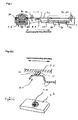
- Fig.7(a) is an overhead view and Fig.7(b) is a cross section of a conventional magnetic head support mechanism.
- magnetic heads 70 and 71 are placed next to each other in a direction perpendicular to the card transferring direction.
- Magnetic head 70 is supported by head support plate 72 while magnetic head 71 is supported by head support plate 73.
- Head support plates 72 and 73 are formed of a rigid material and restrained by two positioning pins 80 and 81 formed on a head support mechanism body (not shown). Accordingly, magnetic heads 70 and 71 supported by head support plates 72 and 73 can rock and move back and forth.
- Leaf spring 74 is formed above head support plates 72 and 73 and is fixed to part 90 (see Fig.7(b)) of the head support mechanism body (not shown) with fixing portions 91 and 92 such as screws.
- the end of leaf spring 74 is split into two pieces (arm portions); one of the arm portions, 75, applies pressure on head support plate 72 towards the magnetic card (downward in Fig.7(b)) while other arm portion, 76, applies pressure on head support plate 73 towards the magnetic card (downward in Fig.7(b)).
- each arm portion 75 and 76 which is facing head support plate 72 and 73, respectively, is warped to form a hemisphere.
- a section of each arm portion 75 and 76 that contacts head support plates 72 and 73 has a hemispheric projecting portion 77 and 78, respectively. Accordingly, projecting portion 77 of arm portion 75 applies pressure on head support plate 72 towards the magnetic card while projecting portion 78 of arm portion 76 applies pressure on head support plate 73 towards the magnetic card.
- magnetic heads 70 and 71 contact the magnetic card with a given pressure applied by a pad placed across from magnetic heads 70, 71.
- head support plates 72 and 73 are able to rock in the direction perpendicular to the card transferring direction with the two positioning pins 80 and 81 as an axis.
- Positioning pins 80 and 81 also function as axes for rocking motion of the magnetic heads 70 and 71.
- a disadvantage of the above-described arrangement is that the head support plates 72 and 73 and leaf spring 74 are separate parts. Therefore, if the relative position of head support plates 72 and73 and leaf spring 74 is not precise during assembly of these parts, projecting portions 77 and 78 are displaced from the line between positioning pins 80 and 81. As a result, application of pressure by the projecting portions 77 and 78 to head support plates 72 and 73 is no longer along the axis. Additionally, it is difficult to precisely position the head support plates 72 and 73 and leaf plate 74 to enable the projecting portions 77 and 78 to apply pressure to the head support plates 72 and 73 on the line between positioning pins 80 and 81 towards the magnetic card.
- An object of the invention is to overcome some of the problems associated with conventional technology.
- a head support mechanism comprising head support plates which support magnetic heads such that the magnetic heads can rock and move back and forth on a plane perpendicular to the card transferring direction; a leaf spring which applies pressure to said head support plates towards a magnetic card such that said magnetic heads come in contact with the magnetic card; wherein a projecting portion is formed on the head support plate in the direction perpendicular to the card transferring direction to contact a pressure applying portion formed on the leaf spring such that the leaf spring applies pressure to the projecting portions.
- either the pressure applying portion of the leaf spring or the projecting portion of the head support plate is elongated in the present invention. Therefore, even when the relative positions of the head support plates and the leaf spring are not precise, the leaf spring can continuously apply pressure to the head support plate at a constant position, that is, the projecting portion of the head support plate. Accordingly, the magnetic heads can be brought in contact with the magnetic card with high accuracy.
- the head support plates may be restrained by two positioning pins in the card transferring direction such that the magnetic heads which are supported by the head support plates can rock and move back and forth.
- the pressure applying portion of the leaf spring may be warped, and the projecting portion of the head support plate is formed as a projection. Hence, the head support plate can rock. Accordingly, even when the relative positions of the head support plates and the leaf spring are not precise, the leaf spring can continuously apply pressure to the head support plate at a constant position, that is, the projecting portion of the head support plate. Therefore, the magnetic heads can be brought in contact with the magnetic card with high accuracy. direction.
- the other part has a horizontal portion that extends in the card transferring direction.
- the leaf spring can continuously apply pressure to the head support plate at a constant position, that is, the projecting portion of the head support plate. Therefore, the magnetic heads can be brought in contact with the magnetic card with high accuracy.
- the projecting portion is placed on a line between the two positioning pins, or it is placed off the line such that the magnetic heads correspond to a card that is warped or does not stand straight. Therefore, such a card that is warped or tilted can be precisely followed by the magnetic heads.
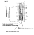
- Figs.1, 5(a) and 5(b) show magnetic heads 1 and 2 that are placed next to each other in the direction perpendicular to the card transferring direction. Magnetic heads 1 and 2 are positioned such that the surface of the magnetic heads having gaps extends over the card transferring path. Magnetic heads 1 and 2 perform magnetic processing, such as reading and writing of magnetic information, on a magnetic strip 4 of the magnetic card 3, which is transferred on the card transferring path of the magnetic card reader.
- Magnetic head 1 is fixed to one end of head support plate 5 with an adhesive or the like.
- Head support plate 5 is formed of a rigid material and is restrained by two positioning pins 5a and 5b formed on a head support mechanism body (not shown). Positioning pins 5a and 5b, especially 5a, function as a guide so that the head support plate 5 rocks within a given range in a direction perpendicular to the card transferring direction.
- head support plate 5 can rock and move back and forth in a plane perpendicular to the card transferring direction, with the positioning pins 5a and 5b functioning as an axis of the rocking motion. Head support plate 5 can also rock around positioning pins 5a and 5b such that magnetic head 1 can follow the warped shape of magnetic card 3. In addition, head support plate 5 has projecting portion 11 on a line between positioning pins 5a and 5b. This will be discussed later.
- magnetic head 2 this is fixed to one end of head support plate 6 using an adhesive or the like (2A of Fig. 1) and supported thereby so that it can rock and move back and forth within a plane perpendicular to the card transferring direction.
- Head support plate 6 is formed of a rigid material and is restrained by two positioning pins 6a and 6b that are formed on a head support mechanism body (not shown). Therefore, magnetic head 2 supported by head support plate 6 can rock and move back and forth, with the positioning pins 6a and 6b forming an axis for the rocking motion. Therefore, the head support plate 6 can rock around positioning pins 6a and 6b such that magnetic head 2 can follow the warped shape of magnetic card 3.
- projecting portion 12 is formed on a position displaced from a line between positioning pins 6a and 6b to correspond to the warped shape of a magnetic card. In other words, when it is desirable to shift the position of projecting portion 12 off the line between the positioning pins to correspond to the warped shape of magnetic card 3, it is arranged so (see Fig.5).
- the head support plates 5 and 6 each have a leaf spring 17.
- Leaf spring 17 is mounted onto part 10 (see Fig.1) of the head support mechanism body (not shown) with fixing members 7a and 7b, such as screws.
- One end of the leaf spring 17 is split into two pieces (arm portions).
- the edge of the arm portions form pressure applying portions 8 and 9.
- Pressure applying portion 8 applies pressure to head support plate 5 towards the magnetic card (upwards in Fig.1) such that magnetic head 1 comes in contact with magnetic card 3
- pressure applying portion 9 applies pressure to head support plate 6 toward the magnetic card (upwards in Fig.1) such that magnetic head 2 comes in contact with magnetic card 3.
- pressure applying portions 8 and 9 of leaf spring 17 are warped such that the side thereof facing head support plates 5 and 6 is convex.
- head support plate 5 has hemispheric projecting portion 11 at the position in contact with pressure applying portion 8, in a direction perpendicular to the card transferring direction.
- Projecting portion 11 is formed as an integral portion of head support plate 5 that projects such that head support plate 5 can rock. Therefore, when pressure applying portion of leaf spring 17 applies pressure to projecting portion 11, head support plate 5 is pushed towards the magnetic card (upwards in Fig.1). Accordingly, magnetic head 1 is brought in contact with magnetic card 3 with a given pressure applied by a pad or the like placed across from magnetic head 1.
- head support plate 6 has hemispheric projecting portion 12 at the position in contact with pressure applying portion 9 in a direction perpendicular to the card transferring direction.
- Projecting portion 12 is formed as an integral projection of head support plate 6 that projects such that head support plate 6 can rock. Therefore, when pressure applying portion of leaf spring 17 applies pressure to projecting portion 12, head support plate 6 is pushed towards the magnetic card (upwards in Fig.1).
- magnetic head 2 is brought in contact with magnetic card 3 with a given pressure applied by a pad or the like placed across from magnetic head 1.
- magnetic heads 1 and 2 have pad roller 15 which also applies a given pressure to magnetic heads 1 and 2 to bring them in contact with the magnetic card 3.
- Either pressure applying portions 8 and 9 of leaf spring 17 or projecting portions 11 and 12 of head support plates 5 and 6 are elongated to a given length such that the pressure applying portions and the projecting portions come in contact with each other.
- Fig. 2(a) shows a configuration in which a part of pressure applying portions 8 and 9 of leaf spring 17 is extended in the card transferring direction to form horizontal portion 16. Accordingly, projecting portions 11 and 12 contact pressure applying portions 8 and 9 of leaf spring 17 within the length of horizontal portion 16 of pressure applying portions 8 and 9.
- projecting portions 11 and 12 of head support plates 5 and 6, on one side in relation to the card transferring direction, are formed to contact pressure applying portions 8 and 9 of leaf spring 17 on the other side at one point thereof wherein pressure applying portions 8 and 9 have horizontal portion 16 which extends in the card transferring direction.
- projections 11 and 12 these are generally shaped as hemispheres as shown in Fig. 2(b).
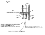
- projecting portion 11 contacts pressure applying portion 8 of leaf spring 17 at one point. This contacting point is located on the line between positioning pins 5a and 5b as shown in Fig.5(a). Also, projecting portion 12 contacts pressure applying portion 9 of leaf spring 17 at one point. This contacting point is located off the line between positioning pins 6a and 6b to correspond to the warped shape of magnetic card 3 (see Fig.6(a)).
- projecting portion 12 of head support plate 6 is displaced from the line between positioning pins 6a and 6b; it contacts pressure applying portion 9 of leaf spring 17 at this position. Therefore, as shown in Fig.6(b), even though the surface of magnetic card 3 having a magnetic strip is warped, magnetic head 2 can excellently follow the warped shape of magnetic card 3 by rocking head support plate 6 around the positioning pins.
- projecting portion 11 of head support plate 5 is brought in contact with pressure applying portion 8 of leaf spring 17 on the line between the positioning pins while projecting portion 12 of head support plate 5 is brought in contact with pressure applying portion 9 of leaf spring 17 at a position off the line to correspond the warp of magnetic card 3.
- projecting portion 11 of head support plate 5 can also be brought in contact with pressure applying portion 8 at a position off the line, if magnetic card 3 is warped towards both magnetic head 1 and magnetic head 2. Accordingly, magnetic head 1 can precisely follow the warped shape of magnetic card 3.
- a part of pressure applying portions 8 and 9 of leaf spring 17 is formed as horizontal portion 16, extended in the card transferring direction such that projecting portions 11 and 12 of head support plates 5 and 6 contact pressure applying portions 8 and 9 of leaf spring 17 within a length of horizontal portion 16.
- a horizontal portion may be formed on projecting portions 11 and 12 of head support plates 5 and 6 in the card transferring direction while pressure applying portions 8 and 9 of leaf spring 17 may be warped to form a hemisphere. Then, pressure applying portions 8 and 9 can contact projecting portions 11 and 12 within a length of the horizontal portion of projecting portions 11 and 12.
- the projecting portions 11 and 12 are formed as semi-cylindrical projections, (which may be an indentation in the support plate) as shown in Figure 4.
- magnetic card 3 When magnetic card 3 is swiped on the card transferring path of the magnetic card reader, magnetic card 3 may not be parallel to the plane on the card transferring path such that it may be transferred towards magnetic heads 1 and 2 while one end is hanging in the air. In such a case, magnetic heads 1 and 2 can precisely follow the card in the configuration according to the present invention.
- the present invention provides a head support mechanism in a magnetic card reader comprising a head support plate that supports a magnetic head such that said magnetic head is able to rock and move in a plane perpendicular to the direction in which a magnetic card is transferred and a leaf spring for applying pressure to said head support plates towards the magnetic card such that the magnetic head comes in contact with said magnetic card.
- a projecting portion Formed on the head support plate is a projecting portion, which extends in a direction perpendicular to the card transferring direction and is provided for contacting a pressure applying portion formed on the leaf spring.
Landscapes
- Adjustment Of The Magnetic Head Position Track Following On Tapes (AREA)
- Magnetic Treatment Devices (AREA)
- Common Mechanisms (AREA)
- Conveying Record Carriers (AREA)
Applications Claiming Priority (2)
| Application Number | Priority Date | Filing Date | Title |
|---|---|---|---|
| JP25468699A JP3602379B2 (ja) | 1999-09-08 | 1999-09-08 | 磁気カードリーダにおけるヘッド保持機構 |
| JP25468699 | 1999-09-08 |
Publications (3)
| Publication Number | Publication Date |
|---|---|
| EP1083551A2 true EP1083551A2 (de) | 2001-03-14 |
| EP1083551A3 EP1083551A3 (de) | 2003-06-04 |
| EP1083551B1 EP1083551B1 (de) | 2006-11-02 |
Family
ID=17268467
Family Applications (1)
| Application Number | Title | Priority Date | Filing Date |
|---|---|---|---|
| EP00307797A Expired - Lifetime EP1083551B1 (de) | 1999-09-08 | 2000-09-08 | Kopfträgermechanismus in einem Magnetkartenleser |
Country Status (5)
| Country | Link |
|---|---|
| US (1) | US6487046B1 (de) |
| EP (1) | EP1083551B1 (de) |
| JP (1) | JP3602379B2 (de) |
| AT (1) | ATE344520T1 (de) |
| DE (1) | DE60031612T8 (de) |
Cited By (1)
| Publication number | Priority date | Publication date | Assignee | Title |
|---|---|---|---|---|
| US6487046B1 (en) | 1999-09-08 | 2002-11-26 | Sankyo Seiki Mfg. Co., Ltd. | Head support mechanism in magnetic card reader |
Families Citing this family (5)
| Publication number | Priority date | Publication date | Assignee | Title |
|---|---|---|---|---|
| WO2005060491A2 (en) * | 2003-11-18 | 2005-07-07 | Magtek, Inc. | Self-aligning magnetic read head incorporating lift-up detection |
| JP4689411B2 (ja) * | 2005-08-31 | 2011-05-25 | 日本電産サンキョー株式会社 | 磁気ヘッド組、磁気記録媒体処理装置及び磁気ヘッド保持用の枠体 |
| JP5651360B2 (ja) * | 2010-03-26 | 2015-01-14 | 日本電産サンキョー株式会社 | カードリーダの磁気ヘッド保持機構およびカードリーダ |
| EP2649616B1 (de) | 2010-12-07 | 2019-02-13 | Ingenico Group | Vorrichtung zur unterstützung eines magnetlesekopfs |
| WO2016069783A1 (en) | 2014-10-28 | 2016-05-06 | Poynt, Co. | Low-profile card reader |
Family Cites Families (12)
| Publication number | Priority date | Publication date | Assignee | Title |
|---|---|---|---|---|
| JPS58122615A (ja) * | 1982-01-18 | 1983-07-21 | Sankyo Seiki Mfg Co Ltd | 複数チヤンネル磁気ヘツド保持機構 |
| JPS63144470A (ja) * | 1986-12-06 | 1988-06-16 | Matsushita Electric Ind Co Ltd | 磁気ヘツド支持装置 |
| DE68929147T2 (de) * | 1988-10-14 | 2000-09-21 | Omron Corp., Kyoto | Kartenlesegerät mit Verriegelung |
| US4937438A (en) * | 1988-11-23 | 1990-06-26 | Datacard Corporation | Magnetic encoding apparatus and method |
| DE3910880A1 (de) * | 1989-04-04 | 1990-10-11 | Amphenol Tuchel Elect | Kardanische aufhaengung fuer magnetkoepfe |
| US5107099A (en) * | 1989-04-24 | 1992-04-21 | Smith Malcolm G | Magnetic card reader and method |
| US5191198A (en) * | 1991-03-22 | 1993-03-02 | Transaction Technology, Inc. | Gimbal card reader |
| US5463678A (en) * | 1993-03-26 | 1995-10-31 | Claircom Communications Group, Inc. | Credit card reader |
| US5559317A (en) * | 1995-03-27 | 1996-09-24 | International Verifact Inc. | Card reader with carriage powered by movement of inserted card |
| US6250552B1 (en) * | 1996-11-15 | 2001-06-26 | Sankyo Seiki Mfg. Co., Ltd. | Card reader having means for reducing the size of the card reader |
| US6042010A (en) * | 1997-01-10 | 2000-03-28 | Matsushita Electric Industrial Co., Ltd. | Card reader and a method of installing a card reader |
| JP3602379B2 (ja) | 1999-09-08 | 2004-12-15 | 株式会社三協精機製作所 | 磁気カードリーダにおけるヘッド保持機構 |
-
1999
- 1999-09-08 JP JP25468699A patent/JP3602379B2/ja not_active Expired - Lifetime
-
2000
- 2000-09-08 US US09/658,320 patent/US6487046B1/en not_active Expired - Lifetime
- 2000-09-08 EP EP00307797A patent/EP1083551B1/de not_active Expired - Lifetime
- 2000-09-08 DE DE60031612T patent/DE60031612T8/de active Active
- 2000-09-08 AT AT00307797T patent/ATE344520T1/de not_active IP Right Cessation
Cited By (1)
| Publication number | Priority date | Publication date | Assignee | Title |
|---|---|---|---|---|
| US6487046B1 (en) | 1999-09-08 | 2002-11-26 | Sankyo Seiki Mfg. Co., Ltd. | Head support mechanism in magnetic card reader |
Also Published As
| Publication number | Publication date |
|---|---|
| DE60031612D1 (de) | 2006-12-14 |
| EP1083551B1 (de) | 2006-11-02 |
| JP2001084722A (ja) | 2001-03-30 |
| DE60031612T2 (de) | 2007-09-13 |
| US6487046B1 (en) | 2002-11-26 |
| ATE344520T1 (de) | 2006-11-15 |
| DE60031612T8 (de) | 2007-12-27 |
| JP3602379B2 (ja) | 2004-12-15 |
| EP1083551A3 (de) | 2003-06-04 |
Similar Documents
| Publication | Publication Date | Title |
|---|---|---|
| US4028734A (en) | Plural magnetic head assembly with independently supporting structure | |
| US4167765A (en) | Transducer suspension mount apparatus | |
| US4628386A (en) | Magnetic reading and/or writing head support assembly | |
| EP1083551B1 (de) | Kopfträgermechanismus in einem Magnetkartenleser | |
| CN1005937B (zh) | 一种特别适用于盒式磁带的磁带支撑片簧 | |
| EP0214597A1 (de) | Gerät zur magnetischen Aufzeichnung und Wiedergabe | |
| CN103824567A (zh) | 磁头单元保持机构、读卡器 | |
| JP3941431B2 (ja) | 磁気ヘッドユニット | |
| JPH0313914Y2 (de) | ||
| JP2000099651A (ja) | Icカ―ドインタフェ―ス機構 | |
| KR910007916B1 (ko) | 자기헤드 지지장치 | |
| JPS6117546Y2 (de) | ||
| JP2868687B2 (ja) | 磁気カードリーダ | |
| JPH02796B2 (de) | ||
| JP2986553B2 (ja) | 磁気ヘッド支持装置 | |
| JPH0337190Y2 (de) | ||
| JPS61158022A (ja) | 磁気ヘツド装置 | |
| JPH0573861A (ja) | 磁気カードリーダの磁気ヘツド支持装置 | |
| JP6096073B2 (ja) | 磁気ヘッド保持機構、カード処理装置 | |
| JP2007233599A (ja) | 磁気ヘッド用ガイド | |
| JPH0818750A (ja) | 画像読取装置 | |
| JPH0329827Y2 (de) | ||
| JPH0991474A (ja) | カード状磁気記録媒体処理装置 | |
| JPH0376071A (ja) | 磁気ヘッドスライダ支持機構 | |
| GB2107915A (en) | Transducing apparatus |
Legal Events
| Date | Code | Title | Description |
|---|---|---|---|
| PUAI | Public reference made under article 153(3) epc to a published international application that has entered the european phase |
Free format text: ORIGINAL CODE: 0009012 |
|
| AK | Designated contracting states |
Kind code of ref document: A2 Designated state(s): AT BE CH CY DE DK ES FI FR GB GR IE IT LI LU MC NL PT SE |
|
| AX | Request for extension of the european patent |
Free format text: AL;LT;LV;MK;RO;SI |
|
| PUAL | Search report despatched |
Free format text: ORIGINAL CODE: 0009013 |
|
| AK | Designated contracting states |
Designated state(s): AT BE CH CY DE DK ES FI FR GB GR IE IT LI LU MC NL PT SE |
|
| AX | Request for extension of the european patent |
Extension state: AL LT LV MK RO SI |
|
| 17P | Request for examination filed |
Effective date: 20031125 |
|
| AKX | Designation fees paid |
Designated state(s): AT BE CH CY DE DK ES FI FR GB GR IE IT LI LU MC NL PT SE |
|
| AXX | Extension fees paid |
Extension state: LV Payment date: 20031125 Extension state: RO Payment date: 20031125 Extension state: SI Payment date: 20031125 Extension state: LT Payment date: 20031125 Extension state: AL Payment date: 20031125 Extension state: MK Payment date: 20031125 |
|
| GRAP | Despatch of communication of intention to grant a patent |
Free format text: ORIGINAL CODE: EPIDOSNIGR1 |
|
| RAP1 | Party data changed (applicant data changed or rights of an application transferred) |
Owner name: NIDEC SANKYO CORPORATION |
|
| GRAS | Grant fee paid |
Free format text: ORIGINAL CODE: EPIDOSNIGR3 |
|
| GRAA | (expected) grant |
Free format text: ORIGINAL CODE: 0009210 |
|
| AK | Designated contracting states |
Kind code of ref document: B1 Designated state(s): AT BE CH CY DE DK ES FI FR GB GR IE IT LI LU MC NL PT SE |
|
| AX | Request for extension of the european patent |
Extension state: AL LT LV MK RO SI |
|
| PG25 | Lapsed in a contracting state [announced via postgrant information from national office to epo] |
Ref country code: AT Free format text: LAPSE BECAUSE OF FAILURE TO SUBMIT A TRANSLATION OF THE DESCRIPTION OR TO PAY THE FEE WITHIN THE PRESCRIBED TIME-LIMIT Effective date: 20061102 Ref country code: LI Free format text: LAPSE BECAUSE OF FAILURE TO SUBMIT A TRANSLATION OF THE DESCRIPTION OR TO PAY THE FEE WITHIN THE PRESCRIBED TIME-LIMIT Effective date: 20061102 Ref country code: BE Free format text: LAPSE BECAUSE OF FAILURE TO SUBMIT A TRANSLATION OF THE DESCRIPTION OR TO PAY THE FEE WITHIN THE PRESCRIBED TIME-LIMIT Effective date: 20061102 Ref country code: NL Free format text: LAPSE BECAUSE OF FAILURE TO SUBMIT A TRANSLATION OF THE DESCRIPTION OR TO PAY THE FEE WITHIN THE PRESCRIBED TIME-LIMIT Effective date: 20061102 Ref country code: FI Free format text: LAPSE BECAUSE OF FAILURE TO SUBMIT A TRANSLATION OF THE DESCRIPTION OR TO PAY THE FEE WITHIN THE PRESCRIBED TIME-LIMIT Effective date: 20061102 Ref country code: CH Free format text: LAPSE BECAUSE OF FAILURE TO SUBMIT A TRANSLATION OF THE DESCRIPTION OR TO PAY THE FEE WITHIN THE PRESCRIBED TIME-LIMIT Effective date: 20061102 |
|
| REG | Reference to a national code |
Ref country code: GB Ref legal event code: FG4D |
|
| REG | Reference to a national code |
Ref country code: IE Ref legal event code: FG4D |
|
| REG | Reference to a national code |
Ref country code: CH Ref legal event code: EP |
|
| REF | Corresponds to: |
Ref document number: 60031612 Country of ref document: DE Date of ref document: 20061214 Kind code of ref document: P |
|
| PG25 | Lapsed in a contracting state [announced via postgrant information from national office to epo] |
Ref country code: SE Free format text: LAPSE BECAUSE OF FAILURE TO SUBMIT A TRANSLATION OF THE DESCRIPTION OR TO PAY THE FEE WITHIN THE PRESCRIBED TIME-LIMIT Effective date: 20070202 Ref country code: DK Free format text: LAPSE BECAUSE OF FAILURE TO SUBMIT A TRANSLATION OF THE DESCRIPTION OR TO PAY THE FEE WITHIN THE PRESCRIBED TIME-LIMIT Effective date: 20070202 |
|
| PG25 | Lapsed in a contracting state [announced via postgrant information from national office to epo] |
Ref country code: ES Free format text: LAPSE BECAUSE OF FAILURE TO SUBMIT A TRANSLATION OF THE DESCRIPTION OR TO PAY THE FEE WITHIN THE PRESCRIBED TIME-LIMIT Effective date: 20070213 |
|
| PG25 | Lapsed in a contracting state [announced via postgrant information from national office to epo] |
Ref country code: PT Free format text: LAPSE BECAUSE OF FAILURE TO SUBMIT A TRANSLATION OF THE DESCRIPTION OR TO PAY THE FEE WITHIN THE PRESCRIBED TIME-LIMIT Effective date: 20070402 |
|
| LTIE | Lt: invalidation of european patent or patent extension |
Effective date: 20061102 |
|
| NLV1 | Nl: lapsed or annulled due to failure to fulfill the requirements of art. 29p and 29m of the patents act | ||
| REG | Reference to a national code |
Ref country code: CH Ref legal event code: PL |
|
| EN | Fr: translation not filed | ||
| PLBE | No opposition filed within time limit |
Free format text: ORIGINAL CODE: 0009261 |
|
| STAA | Information on the status of an ep patent application or granted ep patent |
Free format text: STATUS: NO OPPOSITION FILED WITHIN TIME LIMIT |
|
| 26N | No opposition filed |
Effective date: 20070803 |
|
| PG25 | Lapsed in a contracting state [announced via postgrant information from national office to epo] |
Ref country code: GR Free format text: LAPSE BECAUSE OF FAILURE TO SUBMIT A TRANSLATION OF THE DESCRIPTION OR TO PAY THE FEE WITHIN THE PRESCRIBED TIME-LIMIT Effective date: 20070203 Ref country code: FR Free format text: LAPSE BECAUSE OF FAILURE TO SUBMIT A TRANSLATION OF THE DESCRIPTION OR TO PAY THE FEE WITHIN THE PRESCRIBED TIME-LIMIT Effective date: 20070615 Ref country code: MC Free format text: LAPSE BECAUSE OF NON-PAYMENT OF DUE FEES Effective date: 20070930 |
|
| PG25 | Lapsed in a contracting state [announced via postgrant information from national office to epo] |
Ref country code: IE Free format text: LAPSE BECAUSE OF NON-PAYMENT OF DUE FEES Effective date: 20070910 |
|
| PG25 | Lapsed in a contracting state [announced via postgrant information from national office to epo] |
Ref country code: FR Free format text: LAPSE BECAUSE OF FAILURE TO SUBMIT A TRANSLATION OF THE DESCRIPTION OR TO PAY THE FEE WITHIN THE PRESCRIBED TIME-LIMIT Effective date: 20061102 |
|
| PG25 | Lapsed in a contracting state [announced via postgrant information from national office to epo] |
Ref country code: CY Free format text: LAPSE BECAUSE OF FAILURE TO SUBMIT A TRANSLATION OF THE DESCRIPTION OR TO PAY THE FEE WITHIN THE PRESCRIBED TIME-LIMIT Effective date: 20061102 Ref country code: LU Free format text: LAPSE BECAUSE OF NON-PAYMENT OF DUE FEES Effective date: 20070908 |
|
| PGFP | Annual fee paid to national office [announced via postgrant information from national office to epo] |
Ref country code: DE Payment date: 20160831 Year of fee payment: 17 Ref country code: GB Payment date: 20160907 Year of fee payment: 17 Ref country code: IT Payment date: 20160921 Year of fee payment: 17 |
|
| REG | Reference to a national code |
Ref country code: DE Ref legal event code: R119 Ref document number: 60031612 Country of ref document: DE |
|
| GBPC | Gb: european patent ceased through non-payment of renewal fee |
Effective date: 20170908 |
|
| PG25 | Lapsed in a contracting state [announced via postgrant information from national office to epo] |
Ref country code: GB Free format text: LAPSE BECAUSE OF NON-PAYMENT OF DUE FEES Effective date: 20170908 Ref country code: DE Free format text: LAPSE BECAUSE OF NON-PAYMENT OF DUE FEES Effective date: 20180404 |
|
| PG25 | Lapsed in a contracting state [announced via postgrant information from national office to epo] |
Ref country code: IT Free format text: LAPSE BECAUSE OF NON-PAYMENT OF DUE FEES Effective date: 20170908 |