EP1083626A2 - Compact frequency selective reflector antenna - Google Patents
Compact frequency selective reflector antenna Download PDFInfo
- Publication number
- EP1083626A2 EP1083626A2 EP00119345A EP00119345A EP1083626A2 EP 1083626 A2 EP1083626 A2 EP 1083626A2 EP 00119345 A EP00119345 A EP 00119345A EP 00119345 A EP00119345 A EP 00119345A EP 1083626 A2 EP1083626 A2 EP 1083626A2
- Authority
- EP
- European Patent Office
- Prior art keywords
- signals
- subreflector
- antenna
- reflector
- frequency
- Prior art date
- Legal status (The legal status is an assumption and is not a legal conclusion. Google has not performed a legal analysis and makes no representation as to the accuracy of the status listed.)
- Withdrawn
Links
- 239000000463 material Substances 0.000 description 5
- 238000004891 communication Methods 0.000 description 4
- 238000000034 method Methods 0.000 description 4
- 238000004590 computer program Methods 0.000 description 3
- 239000000758 substrate Substances 0.000 description 3
- 238000000151 deposition Methods 0.000 description 2
- 238000005530 etching Methods 0.000 description 2
- 238000004519 manufacturing process Methods 0.000 description 2
- 238000004544 sputter deposition Methods 0.000 description 2
- 238000004458 analytical method Methods 0.000 description 1
- 239000000919 ceramic Substances 0.000 description 1
- 239000006260 foam Substances 0.000 description 1
- 238000003875 gradient-accelerated spectroscopy Methods 0.000 description 1
- 238000010561 standard procedure Methods 0.000 description 1
Images


Classifications
-
- H—ELECTRICITY
- H01—ELECTRIC ELEMENTS
- H01Q—ANTENNAS, i.e. RADIO AERIALS
- H01Q15/00—Devices for reflection, refraction, diffraction or polarisation of waves radiated from an antenna, e.g. quasi-optical devices
- H01Q15/0006—Devices acting selectively as reflecting surface, as diffracting or as refracting device, e.g. frequency filtering or angular spatial filtering devices
- H01Q15/0013—Devices acting selectively as reflecting surface, as diffracting or as refracting device, e.g. frequency filtering or angular spatial filtering devices said selective devices working as frequency-selective reflecting surfaces, e.g. FSS, dichroic plates, surfaces being partly transmissive and reflective
- H01Q15/0026—Devices acting selectively as reflecting surface, as diffracting or as refracting device, e.g. frequency filtering or angular spatial filtering devices said selective devices working as frequency-selective reflecting surfaces, e.g. FSS, dichroic plates, surfaces being partly transmissive and reflective said selective devices having a stacked geometry or having multiple layers
-
- H—ELECTRICITY
- H01—ELECTRIC ELEMENTS
- H01Q—ANTENNAS, i.e. RADIO AERIALS
- H01Q15/00—Devices for reflection, refraction, diffraction or polarisation of waves radiated from an antenna, e.g. quasi-optical devices
- H01Q15/0006—Devices acting selectively as reflecting surface, as diffracting or as refracting device, e.g. frequency filtering or angular spatial filtering devices
- H01Q15/0013—Devices acting selectively as reflecting surface, as diffracting or as refracting device, e.g. frequency filtering or angular spatial filtering devices said selective devices working as frequency-selective reflecting surfaces, e.g. FSS, dichroic plates, surfaces being partly transmissive and reflective
- H01Q15/0033—Devices acting selectively as reflecting surface, as diffracting or as refracting device, e.g. frequency filtering or angular spatial filtering devices said selective devices working as frequency-selective reflecting surfaces, e.g. FSS, dichroic plates, surfaces being partly transmissive and reflective used for beam splitting or combining, e.g. acting as a quasi-optical multiplexer
-
- H—ELECTRICITY
- H01—ELECTRIC ELEMENTS
- H01Q—ANTENNAS, i.e. RADIO AERIALS
- H01Q19/00—Combinations of primary active antenna elements and units with secondary devices, e.g. with quasi-optical devices, for giving the antenna a desired directional characteristic
- H01Q19/10—Combinations of primary active antenna elements and units with secondary devices, e.g. with quasi-optical devices, for giving the antenna a desired directional characteristic using reflecting surfaces
- H01Q19/104—Combinations of primary active antenna elements and units with secondary devices, e.g. with quasi-optical devices, for giving the antenna a desired directional characteristic using reflecting surfaces using a substantially flat reflector for deflecting the radiated beam, e.g. periscopic antennas
-
- H—ELECTRICITY
- H01—ELECTRIC ELEMENTS
- H01Q—ANTENNAS, i.e. RADIO AERIALS
- H01Q19/00—Combinations of primary active antenna elements and units with secondary devices, e.g. with quasi-optical devices, for giving the antenna a desired directional characteristic
- H01Q19/10—Combinations of primary active antenna elements and units with secondary devices, e.g. with quasi-optical devices, for giving the antenna a desired directional characteristic using reflecting surfaces
- H01Q19/18—Combinations of primary active antenna elements and units with secondary devices, e.g. with quasi-optical devices, for giving the antenna a desired directional characteristic using reflecting surfaces having two or more spaced reflecting surfaces
- H01Q19/19—Combinations of primary active antenna elements and units with secondary devices, e.g. with quasi-optical devices, for giving the antenna a desired directional characteristic using reflecting surfaces having two or more spaced reflecting surfaces comprising one main concave reflecting surface associated with an auxiliary reflecting surface
- H01Q19/192—Combinations of primary active antenna elements and units with secondary devices, e.g. with quasi-optical devices, for giving the antenna a desired directional characteristic using reflecting surfaces having two or more spaced reflecting surfaces comprising one main concave reflecting surface associated with an auxiliary reflecting surface with dual offset reflectors
-
- H—ELECTRICITY
- H01—ELECTRIC ELEMENTS
- H01Q—ANTENNAS, i.e. RADIO AERIALS
- H01Q19/00—Combinations of primary active antenna elements and units with secondary devices, e.g. with quasi-optical devices, for giving the antenna a desired directional characteristic
- H01Q19/10—Combinations of primary active antenna elements and units with secondary devices, e.g. with quasi-optical devices, for giving the antenna a desired directional characteristic using reflecting surfaces
- H01Q19/18—Combinations of primary active antenna elements and units with secondary devices, e.g. with quasi-optical devices, for giving the antenna a desired directional characteristic using reflecting surfaces having two or more spaced reflecting surfaces
- H01Q19/19—Combinations of primary active antenna elements and units with secondary devices, e.g. with quasi-optical devices, for giving the antenna a desired directional characteristic using reflecting surfaces having two or more spaced reflecting surfaces comprising one main concave reflecting surface associated with an auxiliary reflecting surface
- H01Q19/195—Combinations of primary active antenna elements and units with secondary devices, e.g. with quasi-optical devices, for giving the antenna a desired directional characteristic using reflecting surfaces having two or more spaced reflecting surfaces comprising one main concave reflecting surface associated with an auxiliary reflecting surface wherein a reflecting surface acts also as a polarisation filter or a polarising device
-
- H—ELECTRICITY
- H01—ELECTRIC ELEMENTS
- H01Q—ANTENNAS, i.e. RADIO AERIALS
- H01Q25/00—Antennas or antenna systems providing at least two radiating patterns
- H01Q25/002—Antennas or antenna systems providing at least two radiating patterns providing at least two patterns of different beamwidth; Variable beamwidth antennas
-
- H—ELECTRICITY
- H01—ELECTRIC ELEMENTS
- H01Q—ANTENNAS, i.e. RADIO AERIALS
- H01Q25/00—Antennas or antenna systems providing at least two radiating patterns
- H01Q25/007—Antennas or antenna systems providing at least two radiating patterns using two or more primary active elements in the focal region of a focusing device
-
- H—ELECTRICITY
- H01—ELECTRIC ELEMENTS
- H01Q—ANTENNAS, i.e. RADIO AERIALS
- H01Q5/00—Arrangements for simultaneous operation of antennas on two or more different wavebands, e.g. dual-band or multi-band arrangements
- H01Q5/40—Imbricated or interleaved structures; Combined or electromagnetically coupled arrangements, e.g. comprising two or more non-connected fed radiating elements
- H01Q5/45—Imbricated or interleaved structures; Combined or electromagnetically coupled arrangements, e.g. comprising two or more non-connected fed radiating elements using two or more feeds in association with a common reflecting, diffracting or refracting device
Definitions
- the present invention relates to the field of reflector antennas, and more particularly, to a compact reflector antenna which includes a frequency selective subreflector to provide a plurality of antenna patterns from a single reflector antenna.
- Reflector antennas are frequently used on spacecraft to provide communication links with the ground or other spacecraft's.
- a single spacecraft will typically house multiple antennas to provide multiple communication links. These multiple antennas on a single spacecraft typically operate at different frequencies and are used for uplink and downlink communications with the earth.
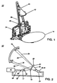
- one method of providing multiple frequencies and multiple communication capabilities on a single spacecraft is to utilize a frequency sensitive structure 10, also known as a dichroic structure, as the subreflector 10 in a cassegrain type reflector antenna 12.
- a cassegrain type reflector antenna 12 has a main reflector 14 and a smaller subreflector 10.
- the dichroic subreflector 10 is hyperbolic in shape and has two focal points 16, 17 one located on each side of the subreflector 10.
- the subreflector 10 is placed between the main reflector 12 and the focal point 18 of the main reflector 12 with the convex side 20 of the subreflector 10 facing the main reflector 14.
- the focal point 16 on the concave side 22 of the subreflector 10 is placed at the focal point 18 of the main reflector 14, and, a downlink feed 24, radiating a downlink RF signal at a first frequency, depicted by the lines marked 26, is placed at the focal points 16, 18.
- the dichroic subreflector 10 is configured to pass the downlink RF signal 26 through the subreflector 10 so that the downlink RF signal 26 will be incident on the main reflector 14 which generates therefrom a downlink antenna pattern at the first frequency.
- the dichroic subreflector 10 is configured to reflect the uplink RF signal 30 and redirect it towards the main reflector 14 such that the uplink RF signal 30 will be incident on the main reflector 14 which generates therefrom an uplink antenna pattern at the uplink frequency. In this way, a single reflector 14 can provide antenna patterns at two separate frequencies.
- the uplink and downlink RF signals are typically generated by electronics 34 which are positioned near the reflector 14.
- This antenna 12 requires a long waveguide run 32 from the electronics package 34 to the downlink feed 24 which is lossy, causes design difficulties in the antenna 12 by increasing the structural, temperature and EMI/EMC protection needed by the antenna 12. It also increases manufacturing costs, volume and size required by the antenna 12 as well as the weight of the antenna.
- a multi-pattern reflector antenna for generating first and second antenna patterns from first and second RF signals having first and second frequencies of operation respectively.
- a multi-pattern reflector antenna in accord with the invention, comprises a reflector having a focal point, first and second subreflectors and first and second feeds. The first and second subreflectors are positioned to image the focal point of the reflector at first and second preselected locations respectively.
- the first and second subreflectors partially overlap each other with the overlapping portion of the first subreflector configured to be a frequency selective structure which reflects RF signals having the first frequency of operation and passes RF signals having the second frequency of operation.
- the second subreflector is configured to reflect RF signals having the second frequency of operation.
- the first and second feeds are positioned at the first and second preselected locations respectively and are configured to operate at the first and second frequencies of operation respectively.
- the first and second feeds are configured to radiate the first and second RF signals respectively.
- the first RF signal is incident upon and reflected by the first subreflector which is configured to redirect the first reflected RF signal towards the reflector.
- the second RF signal passes through the overlapping portion of the first subreflector and is incident upon the second subreflector which is configured to redirect the second RF signal towards the reflector.
- the reflector is configured to generate first and second antenna patterns from the first and second reflected RF signals respectively.
- the multi-pattern antenna is configured so that the feeds are more proximate the reflector than the subreflectors.
- the antenna 37 can be configured as a receive only antenna, a transmit only antenna, or a combination transmit/receive antenna.
- the antenna 37 can be configured as a receive only antenna, a transmit only antenna, or a combination transmit/receive antenna.
- the transmit only case will be described but as is known to one skilled in the art, the same concepts apply for the other configurations.
- the antenna 37 is configured to provide first 38 and second 39 antenna patterns from first 40 and second 41 RF signals respectively.
- the antenna 37 includes a reflector 42, a first 44 and second 46 subreflectors and first 48 and second 50 feeds.
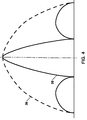
- the reflector 42 is preferably configured in an offset parabolic configuration having a focal point 52 which is offset from the reflector 42, but can be any reflector configuration known to one skilled in the art.
- the first 44 and second 46 subreflectors are offset from each other and are preferably configured as separate structures which are each held in a preselected location by a support structure (not shown).
- the first subreflector 44 is configured as a frequency selective structure which reflects RF signals having the first frequency of operation and passes RF signals having the second frequency of operation.
- the first subreflector 44 is additionally configured and positioned to provide an image of the focal point 52 at a first preselected imaged location 54; and, the second subreflector 46 is configured and positioned to provide an image of the focal point 52 at a second preselected imaged location 56.
- the position of each subreflector 44, 46 results in the subreflectors 44, 46 overlapping each other.
- Each subreflector 44, 46 can be in the shape of a flat plate or in the shape of a hyperbola with the exact shape and position of each subreflector 44, 46 being determined by the desired location of the first 54 and second 56 imaged locations.
- the exact shape and position of each subreflector 44, 46 is selected with the aid of a computer program such as GRASP, which is commercially marketed by TICRA.
- First 48 and second 50 feeds are positioned at or about the first 54 and second 56 imaged locations respectively.
- Each feed 48, 50 can be a single feed horn, a cluster of feed horns, or any other radiating means known to one skilled in the art to be used with a reflector type antenna.
- the first 48 and second 50 feeds are adapted to receive first 40 and second 41 RF signals at first and second frequencies of operation respectively, which are preferably approximately 20 and 30 GHz respectively.
- Each feed 48, 50 is coupled to a waveguide, depicted by the lines marked 66 & 68 respectively, which is coupled to an electronics package 70.
- the electronics package 70 generates the first 40 and second 41 RF signals and provides them to the first 48 and second 50 feeds respectively.
- the waveguides 66, 68 are typically lossy and, as such, it is desirable to minimize the length of each waveguide run 66, 68.
- the first 54 and second 56 preselected imaged locations are selected to be as close to the electronics package 70 as possible to minimize waveguide losses.
- the first feed 48 is responsive to the first RF signal 40 and is operative to radiate a first RF signal, depicted by the line marked 72.
- the first feed 48 is configured and positioned to illuminate the first subreflector 44 with the first radiated RF signal 72.
- the second feed 50 is responsive to the second RF signal 41 and is operative to radiate the second RF signal as depicted by the line marked 74.
- the second feed 50 is configured and positioned to illuminate the second subreflector 46 with the second radiated RF signal 74.
- the first subreflector 44 is configured as a frequency selective structure which reflects RE signals having the first frequency of operation and passes RF signals having the second frequency of operation.
- the first radiated RF signal 72 is incident on the first subreflector 44 which reflects the first radiated RF signal 72 and redirects the first radiated RF signal 72 towards the reflector 42, as depicted by the line marked 78, and the second radiated RF signal 74 passes through the second subreflector 46.
- the redirected first RF signal 78 is incident on the reflector 42 and is reflected by the reflector 42 which generates therefrom the first antenna pattern 38.
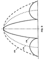
- the configuration and shape of the reflector 42 is selected to provide a first antenna pattern 38 which has a preselected beamwidth and is at the same frequency of operation as the first RF signal 40.
- the second radiated RF signal 74 passes through the portion of the first subreflector 44 which overlaps the second subreflector 46 and is incident on the second subreflector 46.
- the second subreflector 46 is configured to redirect the second radiated RF signal 74 towards the reflector 42 as indicated by the line marked 80.
- the second subreflector 46 is configured as a frequency selective structure which passes RF signals 72 having the first frequency of operation and reflects RF signals 74 having the second frequency of operation.
- the path between the second subreflector 46 and the reflector 42 is at least partially obstructed by the first subreflector 44.
- substantially the entire first subreflector 44 is configured to pass RF signals having the first frequency of operation so that the redirected second RF signal 80 passes through the portion of the first subreflector 44 which is in the path of the second redirected RF signal 80.
- the second redirected RF signal 80 passes through any obstructing portion of the first subreflector 44 and is incident on the reflector 42 which generates therefrom an antenna pattern 39 having the same frequency of operation as the second RF signal 68.
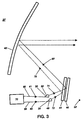
- the antenna 90 is configured to provide downlink 92 and uplink 94 antenna patterns at frequencies of approximately 20 and 30 GHz respectively.
- the antenna 90 is configured in a transmit mode for the 20 GHz signal and in a receive mode for the 30 GHz signal.
- the invention will be described as if the antenna 90 is configured in the transmit mode for the 30 GHz signal.
- the concepts described herein are easily adaptable to provide for a receive mode from the antenna 90.
- the first subreflector 96 is configured to reflect RF signals having a frequency of approximately 20 GHz and pass RF signals having a frequency of approximately 30 GHz. To do so, the first subreflector 96 is typically comprised of a patterned metallic top layer over a dielectric substrate.
- the dielectric substrate is fabricated of materials such as KevlarTM, NomexTM, Ceramic Foam, Rohacell foamTM or the like which are commercially available materials known in the art to pass RF signals with Rohacell foamTM being fabricated by Richmond Aircraft Product Corporation located in Norwalk, California.
- a metallic top layer is first applied to the dielectric substrate using a vapor depositing or sputtering process and portions of the metallic top layer are removed by an etching technique thereby forming the patterned metallic top layer.
- vapor depositing, sputtering and etching processes can be found in the reference cited above.
- the patterned top layer can be formed on a separate sheet of material and then bonded to the core respectively.
- the patterned top layer typically includes crosses, squares, circles, "Y's” or the like with the exact design and dimensions of the patterned top layer being determined by experimental data coupled with design equations and computer analysis tools such as those found in the book Frequency Selective Surface and Grid Array, by T.K. Wu, published by John Wiley and Sons, Inc.
- the second subreflector 98 does not need to pass any RF signals and thus can be fabricated using standard subreflector fabrication means which are known in the art.
- the second subreflector 98 is formed of a light weight core sandwiched between two facesheets.
- the core and facesheets are fabricated from a material such as KevlarTM, NomexTM, honeycomb, or the like which are all commercially available materials with KevlarTM and NomexTM being fabricated by Hexcel Corporation located in Huntington Beach, California.
- the antenna 90 is preferably configured in an offset cassegrain configuration where the reflector 102 is a parabolic reflector having a focal point 104 and is configured in an offset configuration at an offset height of 25 cm.
- the reflector 102 has an approximate 70 cm diameter and a 70 cm focal length.
- the first 96 and second 98 subreflectors are flat plates which overlap each other.
- the first subreflector 96 is positioned as shown and images the focal point 104 at the first preselected imaged location 110.
- the second subreflector 98 is positioned further from the reflector 102 than the first subreflector 96 and is located at least 1.25 cm away from the first subreflector 96.
- the second subreflector 98 is configured to image the focal point 104 at the second preselected imaged location 112.
- a first feed horn 114 is positioned at the first imaged location 110 and is coupled to a 20 GHz waveguide, depicted by the line marked 116.
- the first feed horn 114 has an approximately diameter of 3.8 cm and is configured to receive the 20 GHz RF signal and radiate the 20 GHz RF signal as depicted by the line marked 117.
- a second feed horn 118 is positioned at the second imaged location 112 and is coupled to a 30 GHz waveguide, depicted by the line marked 119.
- the second feed horn 118 has an approximate diameter of 2.5 cm and is configured in a receive mode.
- the embodiments of the invention will be detailed as if the antenna 90 were configured in a transmit-only mode, however, it will be obvious to one skilled in the art that the concepts apply to the receive mode as well.
- the 20 and 30 GHz waveguides 116, 119 are coupled to an electronics package 122.
- the electronics package generates the 20 & 30 GHz RF signals and provides those signals to the 20 & 30 GHz waveguides 116, 119 respectively.
- the waveguides 116, 119 supply the 20 & 30 GHz RF signals to the first 114 and second 118 feed horns respectively.
- the first subreflector 96 is configured to reflect the 20 GHz signal 117 and pass the 30 GHz signal 120.
- the second subreflector 98 is configured to reflect the 30 GHz signal 120 and to pass the 20 GHz signal 117.
- the 20 and 30 GHz radiated signals 117, 120 are incident on and reflected by the first 96 and second 98 subreflectors respectively.
- the reflected 20 and 30 GHz are redirected towards the reflector 102 as depicted by the lines marked 123 & 124 respectively.
- the redirected 20 and 30 GHz signals 123 & 124 are each incident on the reflector 102 which generates therefrom first 92 and second 94 antenna patterns at frequencies of 20 and 30 GHz respectively.
- the reflector 102, the subreflectors 96, 98 and the feeds 114, 118 are configured so that the antenna patterns 92, 94 are generated by the reflector 102 free of obstruction by the feeds 114, 118 and subreflectors 96, 98.
- the antenna 129 includes more than two subreflectors 130 - 136 each of which are positioned to image the focal point 140 of the reflector 142 at a different preselected imaged location 144 - 150 respectively.
- a feed 152 - 158 is positioned at each imaged location 144 - 150 respectively and each feed 152 - 158 is configured to radiate a separate RF signal 160 - 166 where each radiated RF signal 160 - 166 is at a different frequency of operation.
- the first feed 152 is configured to radiate a first RF signal 160 having a first frequency of operation
- the second feed 154 is configured to radiate a second RF signal 162 having a second frequency of operation.
- Each subsequent feed 156, 158 is similarly configured to radiate an RF signal 164, 166 respectively having a preselected frequency of operation.
- the nth feed 158 is configured to radiate the nth RF signal having an nth frequency of operation.
- the first subreflector 130 is configured as a frequency selective structure which reflects RF signals 160 having the first frequency of operation and passes RF signals 162 - 166 having the second through nth frequencies of operation.
- the second subreflector 132 is configured as a frequency selective structure which reflects RF signals 162 having the second frequency of operation and passes RF signals 164, 166 having the third through nth frequency of operation.
- each subsequent subreflector is configured to pass and/or reflect signals of preselected frequencies.
- the nth subreflector 136 does not need to pass any RF signals and could therefore be configured to reflect signals of all frequencies. However, as previously mentioned, it is difficult in practice to fabricate a perfect frequency selective structure. As such, the second 132 through the nth 136 subreflectors are preferably each additionally configured to pass the first RF signal and the first through the n-1 RF signal respectively.
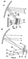
- the antenna 170 could be configured to generate first 172, second 174 and third 176 antenna patterns at frequencies of 20, 30 and 44 GHz respectively.
- the antenna 170 comprises three subreflectors 177 - 179 and three feeds 180 - 182.
- the first 180, second 181 and third 182 feeds are configured to provide first 184, second 186 and third 188 radiated RF signals at frequencies of approximately 20, 30 and 44 GHz respectively.
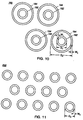
- the first subreflector 177 is configured as a frequency selective structure which reflects RF signals having a frequency of approximately 20 GHz and passes RF signals having frequencies of 30 and 44 GHz. As such, the first RF signal 184 is reflected by the first subreflector 177, and, the second 186 and third 188 RF signals pass through the first subreflector 177. To do so, the first subreflector 177 preferably comprises a patterned metallic top layer over a dielectric core.
- the patterned metallic top layer could consist of a plurality of nested circular loops 190 where each nested circular loop 190 is comprised of an inner loop 192 and an outer loop 194.
- Each inner loop 192 has a diameter D1 and a width W1
- each outer loop 194 has a diameter D2 and width W2 where D1 ⁇ D2 and W1 ⁇ W2 with the exact dimensions of each circular loop 192, 194 being determined with the aid of the computer program mentioned above.
- the nested circular loops 190 will pass RF signals having a frequency of 30 and 44 GHz and reflect RF signals having a frequency of 20 GHz.
- Nested circular loops 190 are preferred for embodiments which pass and reflect RF signals which are closely spaced in frequency.
- the second subreflector 178 is configured as a frequency selective structure which reflects RF signals having a frequency of operation of approximately 30 GHz and passes RF signals having a frequency of operation of approximately 44 GHz.
- the second RF signal 186 is reflected by the second subreflector 178, and, the third RF signal 188 passes through the second subreflector 178.
- the second subreflector 178 preferably comprises a patterned metallic top layer over a dielectric core.
- the Patterned metallic top layer of the second subreflector 178 could consist of a plurality single circular loops 200, each of which having a diameter D3 and a width W3 with the exact dimensions of each circular loop 200 being determined with the aid of the above mentioned computer program. Properly dimensioned, these single circular loops 200 will pass RF signals having frequencies of 44 GHz but will reflect RF signals having a frequency of 30 GHz.
- the third subreflector 179 is configured to reflect RF signals having a frequency of operation of approximately 44GHz. As such, the third RF signal 188 is reflected by the third subreflector 179.
- the third subreflector 179 does not need to pass any RF signals and can thus be fabricated using standard techniques known to one skilled in the art as detailed above.
- the first 184, second 186 and third 188 radiated RF signals are redirected towards the reflector 189 by the first 177, second 178 and third 179 subreflectors respectively.
- the reflector 189 generates first 172, second 114 and third 176 antenna patterns from the first 184, second 186 and third 188 radiated RF signals at frequencies of approximately 20 GHz, 30 GHz and 44 GHz respectively. In this manner, multiple antenna patterns 172 - 176 can be generated from a single reflector 189 free of the need for long waveguide runs.
Landscapes
- Physics & Mathematics (AREA)
- Electromagnetism (AREA)
- Aerials With Secondary Devices (AREA)
- Variable-Direction Aerials And Aerial Arrays (AREA)
Abstract
Description
Claims (9)
- An antenna for generating first and second antenna patterns from first and second RF signals having first and second frequencies of operation respectively, the antenna comprising:a reflector having a focal point;first and second subreflectors configured to image said focal point at first and second preselected locations respectively, said first and second subreflectors partially overlapping each other, the first subreflector configured to be a frequency selective structure which reflects RF signals having said first frequency of operation and passes RF signals having said second frequency of operation, said second subreflector configured to reflect RF signals having said second frequency of operation; and,first and second feeds positioned at said first and second preselected locations respectively and are configured to operate at said first and second frequencies of operation respectively, said first and second feeds responsive to said first and second RF signals respectively and operative to generate first and second radiated RF signals from the first and second RF signals respectively,said first radiated RF signal incident upon and reflected by said first subreflector, said first subreflector configured to redirect said first radiated RF signal towards said reflector,said second radiated RF signal passing through said overlapping portion of said first subreflector and incident upon said second subreflector, said second subreflector configured to redirect said second radiated RF signal towards said reflector,said reflector configured to generate said first and second antenna patterns from said first and second redirected RF signals.
- An antenna in accordance with claim 1, wherein said second subreflector is configured to reflect RF signals having said second frequency of operation and pass RF signals having said first frequency of operation.
- An antenna in accordance with claim 2, wherein said first RF signal is at a frequency of approximately 20 GHz and said second RF signal is at a frequency of approximately 30 GHz.
- An antenna in accordance with claim 3, wherein said first and second feeds are located more proximate said reflector than said subreflectors.
- An antenna as in claim 4, wherein said subreflectors and feeds are positioned so that said first and second antenna patterns are generated by said reflector free of obstruction by said subreflectors and feeds.
- An antenna for generating a plurality of antenna patterns from a plurality of RF signals each of which having a different frequency of operation, the antenna comprising:a reflector having a focal point;a plurality of subreflectors each configured to image said focal point at a different preselected location, one of said subreflectors partially overlapping another one of said subreflectors, the overlapping portion configured to be a frequency selective structure which reflects RF signals having preselected frequencies of operation and passes RF signals having other frequencies of operation; and,a plurality of feeds, one each of which is positioned at each preselected location and is adapted to operate at one of said frequency of operation, each feed responsive to one RF signal and operative to generate one radiated RF signal from said one RF signal, one radiated RF signal passing through said overlapping portion of one subreflector and incident on another subreflector,each radiated RF signal incident upon and reflected by one subreflector, each subreflector configured to redirect one of said plurality of radiated RF signals towards said reflector,said reflector configured to generate one antenna pattern from each redirected RF signal.
- An antenna in accordance with claim 6, wherein said plurality of feeds are each located more proximate said reflector than said subreflectors.
- An antenna in accordance with claim 6, wherein said subreflectors and feeds are positioned so that each of said antenna patterns are generated by said reflector free of obstruction by said subreflectors and feeds.
- An antenna in accordance with claim 8, wherein the positions of said reflector, subreflectors and feeds define an offset cassegrain configuration.
Applications Claiming Priority (2)
| Application Number | Priority Date | Filing Date | Title |
|---|---|---|---|
| US394386 | 1999-09-10 | ||
| US09/394,386 US6545645B1 (en) | 1999-09-10 | 1999-09-10 | Compact frequency selective reflective antenna |
Publications (2)
| Publication Number | Publication Date |
|---|---|
| EP1083626A2 true EP1083626A2 (en) | 2001-03-14 |
| EP1083626A3 EP1083626A3 (en) | 2002-06-26 |
Family
ID=23558752
Family Applications (1)
| Application Number | Title | Priority Date | Filing Date |
|---|---|---|---|
| EP00119345A Withdrawn EP1083626A3 (en) | 1999-09-10 | 2000-09-07 | Compact frequency selective reflector antenna |
Country Status (4)
| Country | Link |
|---|---|
| US (1) | US6545645B1 (en) |
| EP (1) | EP1083626A3 (en) |
| JP (1) | JP2001111333A (en) |
| CA (1) | CA2316658C (en) |
Cited By (9)
| Publication number | Priority date | Publication date | Assignee | Title |
|---|---|---|---|---|
| EP1537628A4 (en) * | 2002-07-23 | 2006-09-27 | Automotive Systems Lab | Multi-beam antenna |
| GB2442796A (en) * | 2006-10-11 | 2008-04-16 | John Thornton | Hemispherical lens with a selective reflective planar surface for a multi-beam antenna |
| US8680450B2 (en) | 2009-06-19 | 2014-03-25 | Mbda Uk Limited | Antennas |
| EP2760081A1 (en) * | 2013-01-28 | 2014-07-30 | BAE Systems PLC | Directional multi-band antenna |
| WO2014114953A3 (en) * | 2013-01-28 | 2014-10-16 | Bae Systems Plc | Directional multi-band antenna |
| WO2018222623A1 (en) * | 2017-05-31 | 2018-12-06 | Hughes Network Systems, Llc | Satellite ground terminal utilizing frequency-selective surface subreflector |
| FR3073347A1 (en) * | 2017-11-08 | 2019-05-10 | Airbus Defence And Space Sas | USEFUL SATELLITE LOAD COMPRISING A REFLECTING DOUBLE-REFLECTING REFLECTOR |
| US10559888B2 (en) | 2015-06-19 | 2020-02-11 | Hughes Network Systems, Llc | Satellite ground terminal utilizing frequency-selective surface diplexer |
| US10658757B2 (en) | 2015-06-19 | 2020-05-19 | Hughes Network Systems, Llc | Satellite ground terminal utilizing frequency-selective surface subreflector |
Families Citing this family (30)
| Publication number | Priority date | Publication date | Assignee | Title |
|---|---|---|---|---|
| US7038632B2 (en) * | 2001-09-14 | 2006-05-02 | Andrew Corporation | Co-located multi-band antenna |
| US6774861B2 (en) * | 2002-06-19 | 2004-08-10 | Northrop Grumman Corporation | Dual band hybrid offset reflector antenna system |
| US6795034B2 (en) * | 2002-07-10 | 2004-09-21 | The Boeing Company | Gregorian antenna system for shaped beam and multiple frequency use |
| US6937201B2 (en) * | 2003-11-07 | 2005-08-30 | Harris Corporation | Multi-band coaxial ring-focus antenna with co-located subreflectors |
| US20080094298A1 (en) * | 2006-10-23 | 2008-04-24 | Harris Corporation | Antenna with Shaped Asymmetric Main Reflector and Subreflector with Asymmetric Waveguide Feed |
| JP5371633B2 (en) * | 2008-09-30 | 2013-12-18 | 株式会社エヌ・ティ・ティ・ドコモ | Reflect array |
| JP5297349B2 (en) * | 2009-11-13 | 2013-09-25 | 株式会社エヌ・ティ・ティ・ドコモ | Reflect array |
| JP6014041B2 (en) | 2010-10-15 | 2016-10-25 | シーレイト リミテッド ライアビリティー カンパニーSearete Llc | Surface scattering antenna |
| WO2014079298A1 (en) * | 2012-11-20 | 2014-05-30 | 深圳光启创新技术有限公司 | Metamaterial, metamaterial preparation method and metamaterial design method |
| US9385435B2 (en) | 2013-03-15 | 2016-07-05 | The Invention Science Fund I, Llc | Surface scattering antenna improvements |
| US9647345B2 (en) | 2013-10-21 | 2017-05-09 | Elwha Llc | Antenna system facilitating reduction of interfering signals |
| US9923271B2 (en) | 2013-10-21 | 2018-03-20 | Elwha Llc | Antenna system having at least two apertures facilitating reduction of interfering signals |
| US9935375B2 (en) | 2013-12-10 | 2018-04-03 | Elwha Llc | Surface scattering reflector antenna |
| US9825358B2 (en) | 2013-12-17 | 2017-11-21 | Elwha Llc | System wirelessly transferring power to a target device over a modeled transmission pathway without exceeding a radiation limit for human beings |
| US9843103B2 (en) * | 2014-03-26 | 2017-12-12 | Elwha Llc | Methods and apparatus for controlling a surface scattering antenna array |
| US9853361B2 (en) | 2014-05-02 | 2017-12-26 | The Invention Science Fund I Llc | Surface scattering antennas with lumped elements |
| US10446903B2 (en) | 2014-05-02 | 2019-10-15 | The Invention Science Fund I, Llc | Curved surface scattering antennas |
| US9882288B2 (en) | 2014-05-02 | 2018-01-30 | The Invention Science Fund I Llc | Slotted surface scattering antennas |
| US9711852B2 (en) | 2014-06-20 | 2017-07-18 | The Invention Science Fund I Llc | Modulation patterns for surface scattering antennas |
| US10461396B2 (en) | 2015-04-03 | 2019-10-29 | Fit Pay, Inc. | System and method for low-power close-proximity communications and energy transfer using a miniature multi-purpose antenna |
| WO2016205396A1 (en) | 2015-06-15 | 2016-12-22 | Black Eric J | Methods and systems for communication with beamforming antennas |
| US9929474B2 (en) | 2015-07-02 | 2018-03-27 | Sea Tel, Inc. | Multiple-feed antenna system having multi-position subreflector assembly |
| KR101757681B1 (en) * | 2016-04-12 | 2017-07-26 | (주)인텔리안테크놀로지스 | Satellite communication antenna capable of receiving multi band signal |
| US10361481B2 (en) | 2016-10-31 | 2019-07-23 | The Invention Science Fund I, Llc | Surface scattering antennas with frequency shifting for mutual coupling mitigation |
| KR102245947B1 (en) * | 2017-04-26 | 2021-04-29 | 한국전자통신연구원 | Transceiver in a wireless communication system |
| FR3067535B1 (en) * | 2017-06-09 | 2023-03-03 | Airbus Defence & Space Sas | TELECOMMUNICATIONS SATELLITE, METHOD FOR BEAM FORMING AND METHOD FOR MAKING A SATELLITE PAYLOAD |
| US11133598B2 (en) | 2017-07-25 | 2021-09-28 | Sea Tel, Inc. | Antenna system with multiple synchronously movable feeds |
| US12283750B2 (en) * | 2018-11-08 | 2025-04-22 | Orbit Communication Systems Ltd. | Low profile multi band antenna system |
| KR102420112B1 (en) | 2022-05-06 | 2022-07-11 | 국방과학연구소 | Apparatus and method of crpa neutralization for illegal unmanned aerial vehicle |
| US12555920B2 (en) * | 2023-08-21 | 2026-02-17 | Eagle Technology, Llc | Antenna with dual-function antenna structure and associated methods |
Family Cites Families (6)
| Publication number | Priority date | Publication date | Assignee | Title |
|---|---|---|---|---|
| JPS54114065A (en) | 1978-02-24 | 1979-09-05 | Nippon Telegr & Teleph Corp <Ntt> | Beam variable antenna |
| US4342036A (en) * | 1980-12-29 | 1982-07-27 | Ford Aerospace & Communications Corporation | Multiple frequency band, multiple beam microwave antenna system |
| IT1180117B (en) * | 1984-11-08 | 1987-09-23 | Cselt Centro Studi Lab Telecom | STRUCTURE FOR DICHROIC ANTENNA |
| US5130718A (en) | 1990-10-23 | 1992-07-14 | Hughes Aircraft Company | Multiple dichroic surface cassegrain reflector |
| US5373302A (en) * | 1992-06-24 | 1994-12-13 | The United States Of America As Represented By The Administrator Of The National Aeronautics And Space Administration | Double-loop frequency selective surfaces for multi frequency division multiplexing in a dual reflector antenna |
| US5576721A (en) * | 1993-03-31 | 1996-11-19 | Space Systems/Loral, Inc. | Composite multi-beam and shaped beam antenna system |
-
1999
- 1999-09-10 US US09/394,386 patent/US6545645B1/en not_active Expired - Lifetime
-
2000
- 2000-08-24 CA CA002316658A patent/CA2316658C/en not_active Expired - Fee Related
- 2000-09-07 EP EP00119345A patent/EP1083626A3/en not_active Withdrawn
- 2000-09-08 JP JP2000273052A patent/JP2001111333A/en active Pending
Cited By (12)
| Publication number | Priority date | Publication date | Assignee | Title |
|---|---|---|---|---|
| EP1537628A4 (en) * | 2002-07-23 | 2006-09-27 | Automotive Systems Lab | Multi-beam antenna |
| GB2442796A (en) * | 2006-10-11 | 2008-04-16 | John Thornton | Hemispherical lens with a selective reflective planar surface for a multi-beam antenna |
| US8680450B2 (en) | 2009-06-19 | 2014-03-25 | Mbda Uk Limited | Antennas |
| EP2760081A1 (en) * | 2013-01-28 | 2014-07-30 | BAE Systems PLC | Directional multi-band antenna |
| WO2014114953A3 (en) * | 2013-01-28 | 2014-10-16 | Bae Systems Plc | Directional multi-band antenna |
| US9865921B2 (en) | 2013-01-28 | 2018-01-09 | Bae Systems Plc | Directional multi-band antenna |
| US10559888B2 (en) | 2015-06-19 | 2020-02-11 | Hughes Network Systems, Llc | Satellite ground terminal utilizing frequency-selective surface diplexer |
| US10658757B2 (en) | 2015-06-19 | 2020-05-19 | Hughes Network Systems, Llc | Satellite ground terminal utilizing frequency-selective surface subreflector |
| WO2018222623A1 (en) * | 2017-05-31 | 2018-12-06 | Hughes Network Systems, Llc | Satellite ground terminal utilizing frequency-selective surface subreflector |
| FR3073347A1 (en) * | 2017-11-08 | 2019-05-10 | Airbus Defence And Space Sas | USEFUL SATELLITE LOAD COMPRISING A REFLECTING DOUBLE-REFLECTING REFLECTOR |
| WO2019092087A1 (en) * | 2017-11-08 | 2019-05-16 | Airbus Defence And Space Sas | Satellite payload comprising a dual reflective surface reflector |
| US10931364B2 (en) | 2017-11-08 | 2021-02-23 | Airbus Defence And Space Sas | Satellite payload comprising a dual reflective surface reflector |
Also Published As
| Publication number | Publication date |
|---|---|
| JP2001111333A (en) | 2001-04-20 |
| CA2316658A1 (en) | 2001-03-10 |
| EP1083626A3 (en) | 2002-06-26 |
| US6545645B1 (en) | 2003-04-08 |
| CA2316658C (en) | 2004-01-06 |
Similar Documents
| Publication | Publication Date | Title |
|---|---|---|
| CA2316658C (en) | Compact frequency selective reflector antenna | |
| US6169524B1 (en) | Multi-pattern antenna having frequency selective or polarization sensitive zones | |
| US4772890A (en) | Multi-band planar antenna array | |
| Shaker et al. | Reflectarray antennas: analysis, design, fabrication, and measurement | |
| US6885355B2 (en) | Spatial filtering surface operative with antenna aperture for modifying aperture electric field | |
| EP0803932B1 (en) | Multiple band folding antenna | |
| US5471224A (en) | Frequency selective surface with repeating pattern of concentric closed conductor paths, and antenna having the surface | |
| US6900763B2 (en) | Antenna system with spatial filtering surface | |
| US6927729B2 (en) | Multisource antenna, in particular for systems with a reflector | |
| US7889127B2 (en) | Wide angle impedance matching using metamaterials in a phased array antenna system | |
| US5608414A (en) | Heat rejecting spacecraft array antenna | |
| CN112117524B (en) | Electronic equipment | |
| JP2897970B2 (en) | Same-surface shaped reflector with semi-tandem structure | |
| WO2004008570A2 (en) | Antenna system with active spatial filtering surface | |
| US20050219145A1 (en) | Complementary dual antenna system | |
| JPH09307343A (en) | Microstrip antenna system | |
| US6747608B2 (en) | High performance multi-band frequency selective reflector with equal beam coverage | |
| WO2015120417A2 (en) | Wideband antenna star array | |
| US2870444A (en) | Radiating systems | |
| US6384795B1 (en) | Multi-step circular horn system | |
| US5486837A (en) | Compact microwave antenna suitable for printed-circuit fabrication | |
| US6593894B1 (en) | Highly directional receiver and source antennas using photonic band gap crystals | |
| EP0986133A2 (en) | Multi-focus reflector antenna | |
| WO2018231844A1 (en) | Parasitic antenna arrays incorporating fractal metamaterials | |
| CN116472645B (en) | A cavity-backed antenna with controllable beam width |
Legal Events
| Date | Code | Title | Description |
|---|---|---|---|
| PUAI | Public reference made under article 153(3) epc to a published international application that has entered the european phase |
Free format text: ORIGINAL CODE: 0009012 |
|
| AK | Designated contracting states |
Kind code of ref document: A2 Designated state(s): AT BE CH CY DE DK ES FI FR GB GR IE IT LI LU MC NL PT SE |
|
| AX | Request for extension of the european patent |
Free format text: AL;LT;LV;MK;RO;SI |
|
| PUAL | Search report despatched |
Free format text: ORIGINAL CODE: 0009013 |
|
| AK | Designated contracting states |
Kind code of ref document: A3 Designated state(s): AT BE CH CY DE DK ES FI FR GB GR IE IT LI LU MC NL PT SE |
|
| AX | Request for extension of the european patent |
Free format text: AL;LT;LV;MK;RO;SI |
|
| RIC1 | Information provided on ipc code assigned before grant |
Free format text: 7H 01Q 19/195 A, 7H 01Q 15/00 B, 7H 01Q 25/00 B, 7H 01Q 19/19 B, 7H 01Q 5/00 B, 7H 01Q 19/10 B |
|
| 17P | Request for examination filed |
Effective date: 20020725 |
|
| 17Q | First examination report despatched |
Effective date: 20030114 |
|
| AKX | Designation fees paid |
Designated state(s): AT BE CH CY DE DK ES FI FR GB GR IE IT LI LU MC NL PT SE |
|
| GRAP | Despatch of communication of intention to grant a patent |
Free format text: ORIGINAL CODE: EPIDOSNIGR1 |
|
| STAA | Information on the status of an ep patent application or granted ep patent |
Free format text: STATUS: THE APPLICATION HAS BEEN WITHDRAWN |
|
| RAP1 | Party data changed (applicant data changed or rights of an application transferred) |
Owner name: NORTHROP GRUMMAN CORPORATION |
|
| RAP1 | Party data changed (applicant data changed or rights of an application transferred) |
Owner name: NORTHROP GRUMMAN CORPORATION |
|
| 18W | Application withdrawn |
Effective date: 20031027 |