EP1084871B1 - Anhängerkupplung mit axialem Verfahrweg - Google Patents
Anhängerkupplung mit axialem Verfahrweg Download PDFInfo
- Publication number
- EP1084871B1 EP1084871B1 EP00119960A EP00119960A EP1084871B1 EP 1084871 B1 EP1084871 B1 EP 1084871B1 EP 00119960 A EP00119960 A EP 00119960A EP 00119960 A EP00119960 A EP 00119960A EP 1084871 B1 EP1084871 B1 EP 1084871B1
- Authority
- EP
- European Patent Office
- Prior art keywords
- rod
- trailer coupling
- coupling according
- operating position
- rest position
- Prior art date
- Legal status (The legal status is an assumption and is not a legal conclusion. Google has not performed a legal analysis and makes no representation as to the accuracy of the status listed.)
- Expired - Lifetime
Links
Images

Classifications
-
- B—PERFORMING OPERATIONS; TRANSPORTING
- B60—VEHICLES IN GENERAL
- B60D—VEHICLE CONNECTIONS
- B60D1/00—Traction couplings; Hitches; Draw-gear; Towing devices
- B60D1/24—Traction couplings; Hitches; Draw-gear; Towing devices characterised by arrangements for particular functions
- B60D1/246—Traction couplings; Hitches; Draw-gear; Towing devices characterised by arrangements for particular functions for actuating the hitch by powered means
-
- B—PERFORMING OPERATIONS; TRANSPORTING
- B60—VEHICLES IN GENERAL
- B60D—VEHICLE CONNECTIONS
- B60D1/00—Traction couplings; Hitches; Draw-gear; Towing devices
- B60D1/01—Traction couplings or hitches characterised by their type
- B60D1/06—Ball-and-socket hitches
-
- B—PERFORMING OPERATIONS; TRANSPORTING
- B60—VEHICLES IN GENERAL
- B60D—VEHICLE CONNECTIONS
- B60D1/00—Traction couplings; Hitches; Draw-gear; Towing devices
- B60D1/48—Traction couplings; Hitches; Draw-gear; Towing devices characterised by the mounting
- B60D1/54—Traction couplings; Hitches; Draw-gear; Towing devices characterised by the mounting collapsible or retractable when not in use, e.g. hide-away hitches
Definitions
- the invention relates to a trailer coupling for motor vehicles, with a Rod on which there is usually a ball, the rod being a moving part between two end positions, namely between a rest position and an operating position, by means of a motor axially in the direction of the rod is adjustable, being between the rest position and the Operating position a swivel angle is provided.
- Such towbars are from the German utility model DE 295 20 254 known.
- an axially extendable Trailer coupling known, which is motor-driven.
- the object of the invention is to provide a trailer coupling with an axial adjustment path to further educate so that the adjustment effort can be reduced and a wider range of applications is achieved.
- the trailer coupling has one spatially particularly wide action area in which the location of the Operating position can be chosen largely freely. This is significant because depending on the installation conditions between the rest position and the Operating position obstacles must be avoided by the rod and the Mounting location on the vehicle and the possible installation conditions depending are very different depending on the vehicle type.
- the trailer coupling has one Has pivot angle about the axis of the rod of about 180 °. This is true especially when the rod has an axis that is approximately vertical is arranged.
- the trailer hitch can for example be installed so that they are from a position behind the bumper of a Vehicle can be pivoted in front of the bumper.
- the swivel angle is approximately 90 ° is.
- the branch in the curve results in different ones Guide sections that can be approached arbitrarily if on Branch a switch with a controllable, for. B. trained as a lock Guidance is provided, especially if it is mechanical.
- the switch can be replaced advantageously if a backdrop is provided, which is guided by the curve, the backdrop switchable is trained.
- the guide curve can then, for example, in individual separate sections may be divided, each by the corresponding switched on backdrop can be scanned.
- one enforces Backdrop with a length that exceeds the diameter of the bar, the whole Pole transverse to the axis direction.
- the backdrop is one suitable mechanics or switched by an electromagnet so that they protrudes only to the desired side and into those provided separately there Intervening leadership curves.
- a mechanical switch can be simplified considerably if the Direction of rotation of the rod from the rest position to the operating position is the same is formed, since then a simple resilient switch tongue is sufficient.
- the Direction of rotation of the spindle when extending the rod the same direction as that Has pivoting direction of the rod can advantageously all on a switch to be dispensed with, since then the backdrop is always on the right edge of the Leadership creates.
- a shaft end is provided on which the rod is cranked is adjustable.
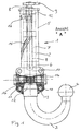
- 1 denotes an adjustable trailer hitch. She has in essentially an axially adjustable rod 2, which is interrupted Lines are shown, and the lower end 3 is bent by 180 °, which ends in a ball 4. Of course, the towbar for example, can also be installed horizontally. Then this is the ball 4 load-bearing end only bent by 90 °.
- the rod 2 is displaceable in the longitudinal direction in a guide sleeve 5 and around their axis rotatably added.
- an axial Bore 6 provided with an internal thread 7.
- a central adjusting spindle 8 By a motor, not shown can be driven via a spur gear 9 provided at the upper end.
- the entire trailer hitch 1 is mounted on a vehicle by by means of screws through the mounting openings 10 of the mounting flange 11 grip, is screwed to the vehicle.
- the rod 2 In the end position shown in FIG. 1, the rod 2 is in via a cone 12 a housing 13 fixed with a corresponding counter surface. An additional Securing in this position is done by mechanical or electromagnetic actuated locking bolts 14 which engage in corresponding bores. A three-ball lock is also conceivable here, for example. The Locking bolts 14 also secure the rod 2 in the rest position form-fitting.
- the guide sleeve 5 To control the axial movement of the rod 2, the guide sleeve 5 incorporated a guide curve 15 shaped as a slot, into which a pin-shaped Setting 16 engages, which is fixed to the rod 2.
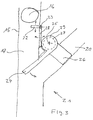
- Figure 2 shows the trailer hitch from a different side view.
- the The backdrop 16 is located at the upper end of the curve 15 in the operating position. When changing from one position to the other, the backdrop 16 passes through one first branch 17 until it occupies its outermost axial position at location 18. The lower end 3 of the rod 2 is shown in broken lines. The The motor is then reversed so that the rod 2 moves up again. Locally 19 branches the curve 15 into a second branch 20, in which the backdrop 16 retracts and thereby gives the rod 2 about its longitudinal axis until the rod 2 in the upper end position their shown in broken lines In the rest position, which is determined by the end of the second branch 20.
- the rest position is in the same plane as that Operating position. But it can also be different.
- the end stops are modified in a suitable form, the cone 12 as wedge-shaped prism.
- the backdrop 16 first passes through the curve 15 from top to bottom. It passes a release lever 22, which is about an axis 23 against the Force of a return spring is pivotable so that the link 16 pass can. Then she presses the switch tongue 24 against the force of another Return spring to the side and passes this, the switch tongue 24th pivots about an axis 25.
- the switch tongue 24 guides the backdrop 16 into the two branch 20 until it opens meets the wedge 26.
- This embodiment is particularly advantageous if a swivel angle of about 90 ° is desired and the rod 2 from one position to the other should return the same way.
- a development of the guide curve 15 is shown schematically in FIG.
- the direction of rotation of the spindle is selected so that the link 16 when Extend to the left side of the guide curve 15. It is when entering then vice versa.
- the backdrop 16 runs automatically when entering the a second branch 20 without a switch.
- the Swiveling direction when moving from one position to the other remains receive.
- the guide curve 15 with its first branch 17 and its second branch 20 can also be divided into two separate curves, one of which can be switched Drive through scenery that either in one or in the other curve engages.
- the switchover takes place in an advantageous manner in the lower end points of the travel paths. You can then also use a switch Advantage to be waived.
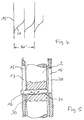
- FIG. 5 Such a switchable backdrop 16 is shown in FIG. 5.
- the backdrop 16 passes through the rod 2, in which it in a bore 31 in the direction of Arrows 30 is slidably received.
- the backdrop 16 is optionally in your lower end position moved to the right or left position so that they engages either in branch 15 or in branch 20.
- the circuit takes place by two actuating magnets provided at this point but not shown or by a suitable mechanical switch.
Landscapes
- Engineering & Computer Science (AREA)
- Transportation (AREA)
- Mechanical Engineering (AREA)
- Vehicle Cleaning, Maintenance, Repair, Refitting, And Outriggers (AREA)
- Pens And Brushes (AREA)
- Mechanical Operated Clutches (AREA)
- Vehicle Body Suspensions (AREA)
- Pivots And Pivotal Connections (AREA)
- Transmission Devices (AREA)
Description
- Fig. 1
- eine Seitenansicht einer erfindungsgemäßen Anhängerkupplung,
- Fig. 2
- eine andere Seitenansicht der erfindungsgemäßen Anhängerkupplung aus Fig. 1,
- Fig. 3
- eine Aufsicht auf eine schematisch dargestellte Weiche,
- Fig. 4
- eine schematische Abwicklung von Führungskurven und
- Fig. 5
- einen Schnitt durch eine Stange mit schaltbarer Kulisse.
- 1
- Anhängerkupplung
- 2
- Stange
- 3
- unteres Ende
- 4
- Kugel
- 5
- Führungshülse
- 6
- Bohrung
- 7
- Innengewinde
- 8
- Verstellspindel
- 9
- Stirnradgetriebe
- 10
- Befestigungsöffnung
- 11
- Montageflansch
- 12
- Konus
- 13
- Gehäuse
- 14
- Verriegelungsbolzen
- 15
- Führungskurve
- 16
- Kulisse
- 17
- erster Zweig
- 18
- Ort
- 19
- Ort
- 20
- zweiter Zweig
- 21
- Weiche
- 22
- Frelgabehebel
- 23
- Achse
- 24
- Weichenzunge
- 25
- Achse
- 26
- Auflaufkeil
- 27
- Welle
- 28
- Sperrklinke
- 29
- Bund
- 30
- Pfeile
- 31
- Bohrung
Claims (14)
- Anhängerkupplung (1) für Kraftfahrzeuge, mit einer Stange (2), an der sich üblicherweise eine Kugel (4) befindet, wobei die Stange (2) als bewegliches Teil zwischen zwei Endlagen, nämlich zwischen einer Ruhestellung und einer Betriebsstellung, mittels eines Motors axial in Richtung der Stange (2) verstellbar ausgebildet ist, wobei zwischen der Ruhestellung und der Betriebsstellung ein Schwenkwinkel vorgesehen ist, dadurch gekennzeichnet, dass die Ruhestellung und die Betriebsstellung eine Einfahrrichtung aufweisen, die gleichsinnig ausgebildet ist.
- Anhängerkupplung nach Anspruch 1, dadurch gekennzeichnet, dass die Stange (2) einen Gesamtverstellweg aufweist, der größer ist als der axiale Abstand zwischen der Ruhestellung und der Betriebsstellung.
- Anhängerkupplung nach Anspruch 1 oder 2, dadurch gekennzeichnet, dass die Stange (2) einen Schwenkwinkel um die Achse der Stange (2) von etwa 90° oder etwa 180° aufweist.
- Anhängerkupplung nach einem oder mehreren der vorhergehenden Ansprüche, dadurch gekennzeichnet, dass die Stange (2) eine Achse aufweist, die etwa vertikal angeordnet ist.
- Anhängerkupplung nach einem oder mehreren der vorhergehenden Ansprüche, dadurch gekennzeichnet, dass die Ruhestellung und die Betriebsstellung in derselben zu der Achse der Stange (2) senkrechten Ebene angeordnet sind.
- Anhängerkupplung nach einem oder mehreren der vorhergehenden Ansprüche, dadurch gekennzeichnet, dass die Stange (2) um die Stangenachse eine Drehbewegung zwischen der Ruhestellung und der Betriebsstellung aufweist, die durch eine Kurve (15) geführt ausgebildet ist.
- Anhängerkupplung nach einem oder mehreren der vorhergehenden Ansprüche, dadurch gekennzeichnet, dass getrennte Anschläge für die Ruhestellung und die Betriebsstellung vorgesehen sind.
- Anhängerkupplung nach Anspruch 6 oder 7, dadurch gekennzeichnet, dass die Kurve (15) mindestens einen Abzweig (17, 20) aufweist.
- Anhängerkupplung nach Anspruch 8, dadurch gekennzeichnet, dass am Ort (19) des Abzweigs (17, 20) eine Weiche (21) mit einer steuerbaren Führung vorgesehen ist.
- Anhängerkupplung nach Anspruch 8, dadurch gekennzeichnet, dass die Führung mechanisch ist.
- Anhängerkupplung nach einem oder mehreren der vorhergehenden Ansprüche, dadurch gekennzeichnet, dass eine Kulisse (16) vorgesehen ist, die gegebenenfalls schaltbar ausgebildet ist.
- Anhängerkupplung nach einem oder mehreren der vorhergehenden Ansprüche, dadurch gekennzeichnet, dass die Drehrichtung der Stange (2) aus der Ruhestellung in die Betriebsstellung gleichsinnig ausgebildet ist.
- Anhängerkupplung nach Anspruch 12, dadurch gekennzeichnet, dass für die axiale Verstellung der Stange (2) ein Spindel-Mutter-Trieb (7, 8) vorgesehen ist, dessen Drehrichtung der Spindel (8) beim Einfahren der Stange (2) dieselbe Richtung wie die Schwenkrichtung der Stange (2) aufweist.
- Anhängerkupplung nach Anspruch 13, dadurch gekennzeichnet, dass ein Wellenende vorgesehen ist, an dem die Stange (2) mittels Handbetätigung verstellbar ist.
Applications Claiming Priority (2)
| Application Number | Priority Date | Filing Date | Title |
|---|---|---|---|
| DE19944264A DE19944264A1 (de) | 1999-09-15 | 1999-09-15 | Anhängerkupplung mit axialem Verfahrweg |
| DE19944264 | 1999-09-15 |
Publications (3)
| Publication Number | Publication Date |
|---|---|
| EP1084871A2 EP1084871A2 (de) | 2001-03-21 |
| EP1084871A3 EP1084871A3 (de) | 2002-01-30 |
| EP1084871B1 true EP1084871B1 (de) | 2003-11-26 |
Family
ID=7922151
Family Applications (1)
| Application Number | Title | Priority Date | Filing Date |
|---|---|---|---|
| EP00119960A Expired - Lifetime EP1084871B1 (de) | 1999-09-15 | 2000-09-14 | Anhängerkupplung mit axialem Verfahrweg |
Country Status (3)
| Country | Link |
|---|---|
| EP (1) | EP1084871B1 (de) |
| AT (1) | ATE255018T1 (de) |
| DE (2) | DE19944264A1 (de) |
Cited By (3)
| Publication number | Priority date | Publication date | Assignee | Title |
|---|---|---|---|---|
| DE102006045465B4 (de) * | 2006-06-09 | 2017-03-02 | Westfalia-Automotive Gmbh | Anhängerkupplung für Kraftfahrzeuge |
| EP4108481A1 (de) | 2021-06-23 | 2022-12-28 | MVG Metallverarbeitungsgesellschaft mbH | Anhängevorrichtung |
| EP4108482A1 (de) | 2021-06-23 | 2022-12-28 | MVG Metallverarbeitungsgesellschaft mbH | Anhängevorrichtung zur anbringung an einem heck eines fahrzeugs |
Families Citing this family (27)
| Publication number | Priority date | Publication date | Assignee | Title |
|---|---|---|---|---|
| DE10104186B4 (de) * | 2001-01-23 | 2010-07-15 | Westfalia-Automotive Gmbh | Anhängerkupplung |
| DE20215508U1 (de) † | 2002-10-09 | 2004-04-01 | Al-Ko Kober Ag | Anhängevorrichtung für Zugfahrzeuge |
| DE10243044B4 (de) * | 2002-09-12 | 2016-01-21 | Westfalia-Automotive Gmbh | Anhängerkupplung |
| DE10243045B4 (de) * | 2002-09-12 | 2016-01-21 | Westfalia-Automotive Gmbh | Anhängerkupplung |
| DE10347816B4 (de) * | 2003-10-10 | 2014-06-05 | Westfalia-Automotive Gmbh | Anhängekupplung mit lastfreier Drehlagereinrichtung |
| DE10347817B4 (de) * | 2003-10-10 | 2014-07-10 | Westfalia-Automotive Gmbh | Anhängekupplung |
| DE10354753B4 (de) | 2003-11-21 | 2014-07-24 | Westfalia-Automotive Gmbh | Anhängekupplung für Kraftfahrzeuge |
| DE202004005795U1 (de) | 2004-04-08 | 2004-07-08 | Fac Gmbh | Anhängerkupplung |
| DE202004005806U1 (de) | 2004-04-08 | 2004-08-19 | Fac Frank Abels Consulting & Technology Gesellschaft Mbh | Anhängerkupplung |
| DE202004005807U1 (de) | 2004-04-08 | 2004-07-08 | Fac Gmbh | Anhängerkupplung |
| DE202004006204U1 (de) | 2004-04-17 | 2004-07-01 | Fac Gmbh | Anhängerkupplung |
| NL1026198C2 (nl) * | 2004-05-14 | 2005-11-15 | Brink Internat B V | Verdraaibare trekhaak. |
| DE102004045869A1 (de) * | 2004-09-20 | 2006-03-23 | Jaeger Cartronix Gmbh | Anhängerkupplung |
| DE102005056217A1 (de) † | 2005-11-25 | 2007-06-06 | Jaeger Cartronix Gmbh | Antriebseinheit für eine Anhängerkupplung |
| EP1902871B2 (de) | 2006-09-18 | 2012-11-28 | WESTFALIA - Automotive GmbH | Anhängekupplung |
| DE102006051096B4 (de) * | 2006-10-25 | 2013-09-12 | Mvg Metallverarbeitungsgesellschaft Mbh | Anhängevorrichtung |
| DE102012025459A1 (de) * | 2012-12-28 | 2014-07-03 | Volkswagen Aktiengesellschaft | Anhängevorrichtung |
| EP3379222B1 (de) | 2017-03-22 | 2020-12-30 | Methode Electronics Malta Ltd. | Auf magnetoelastik basierte sensoranordnung |
| EP3727901B1 (de) | 2017-12-20 | 2025-09-24 | Horizon Global (South Africa) (Pty) Ltd | Deichsel mit einem kupplungskugelsystem |
| US11084342B2 (en) | 2018-02-27 | 2021-08-10 | Methode Electronics, Inc. | Towing systems and methods using magnetic field sensing |
| EP3758959B1 (de) | 2018-02-27 | 2025-11-05 | Methode Electronics, Inc. | Schleppsysteme und -verfahren mit verwendung von magnetfeldmessung |
| US11491832B2 (en) | 2018-02-27 | 2022-11-08 | Methode Electronics, Inc. | Towing systems and methods using magnetic field sensing |
| US11135882B2 (en) | 2018-02-27 | 2021-10-05 | Methode Electronics, Inc. | Towing systems and methods using magnetic field sensing |
| US11221262B2 (en) | 2018-02-27 | 2022-01-11 | Methode Electronics, Inc. | Towing systems and methods using magnetic field sensing |
| DE102018124518A1 (de) * | 2018-10-04 | 2020-04-09 | ACPS Automotive GmbH | Anhängekupplung |
| SE544412C2 (en) * | 2019-03-12 | 2022-05-10 | Brink Towing Systems B V | Retractable towing hook arrangement |
| CN116872656B (zh) * | 2023-07-14 | 2025-08-26 | 浙江致优汽车科技有限公司 | 拖车联接器 |
Family Cites Families (12)
| Publication number | Priority date | Publication date | Assignee | Title |
|---|---|---|---|---|
| US2544185A (en) * | 1948-05-18 | 1951-03-06 | Frank T Sargent | Trailer hitch |
| DE1665838U (de) * | 1953-04-28 | 1953-10-29 | Werner Dipl Ing Schmitz-Steger | Anhaenger-kupplung, insbesondere fuer personenkraftwagen. |
| US3717362A (en) * | 1971-05-18 | 1973-02-20 | T Johnson | Adjustable and retractable trailer hitch |
| DE3328524A1 (de) * | 1983-08-06 | 1985-02-21 | Daimler-Benz Ag, 7000 Stuttgart | Anhaengerkupplung fuer fahrzeuge |
| DE3442514C2 (de) * | 1984-11-22 | 1987-05-07 | SMAT-Fahrzeugtechnik GmbH, 6325 Grebenau | Auswechselbare Kugelkopfkupplung für Fahrzeuge, insbesondere Personenkraftfahrzeuge |
| US4744583A (en) * | 1987-05-27 | 1988-05-17 | Lloyd Blackwood | Motorized wide range tow hitch |
| DE29522075U1 (de) * | 1995-06-16 | 1999-07-15 | Oris Fahrzeugteile Hans Riehle GmbH, 71696 Möglingen | Anhängevorrichtung für insbesondere Personenkraftwagen |
| DE19605570C2 (de) * | 1995-09-13 | 1997-11-13 | Cartron Fahrzeugteile Gmbh | Axial verstellbare Anhängerkupplung für Kraftfahrzeuge |
| DE29520254U1 (de) * | 1995-09-13 | 1996-04-11 | Cartron Fahrzeugteile GmbH, 27367 Sottrum | Anhängerkupplung für Kraftfahrzeuge |
| DE19651562A1 (de) * | 1996-12-11 | 1998-06-18 | Peter Rocca | Anhängekupplung |
| DE19826618C2 (de) * | 1998-06-17 | 2001-05-03 | Peter Rocca | Anhängekupplung |
| DE10004523A1 (de) * | 2000-02-02 | 2001-08-09 | Fac Frank Abels Consult & Tech | Anhängerkupplung |
-
1999
- 1999-09-15 DE DE19944264A patent/DE19944264A1/de not_active Withdrawn
-
2000
- 2000-09-14 EP EP00119960A patent/EP1084871B1/de not_active Expired - Lifetime
- 2000-09-14 DE DE50004544T patent/DE50004544D1/de not_active Expired - Fee Related
- 2000-09-14 AT AT00119960T patent/ATE255018T1/de not_active IP Right Cessation
Cited By (5)
| Publication number | Priority date | Publication date | Assignee | Title |
|---|---|---|---|---|
| DE102006045465B4 (de) * | 2006-06-09 | 2017-03-02 | Westfalia-Automotive Gmbh | Anhängerkupplung für Kraftfahrzeuge |
| EP4108481A1 (de) | 2021-06-23 | 2022-12-28 | MVG Metallverarbeitungsgesellschaft mbH | Anhängevorrichtung |
| EP4108482A1 (de) | 2021-06-23 | 2022-12-28 | MVG Metallverarbeitungsgesellschaft mbH | Anhängevorrichtung zur anbringung an einem heck eines fahrzeugs |
| DE102021116182A1 (de) | 2021-06-23 | 2022-12-29 | Mvg-Metallverarbeitungsgesellschaft Mbh | Anhängevorrichtung zur Anbringung an einem Heck eines Fahrzeugs |
| DE102021116185A1 (de) | 2021-06-23 | 2022-12-29 | Mvg-Metallverarbeitungsgesellschaft Mbh | Anhängevorrichtung |
Also Published As
| Publication number | Publication date |
|---|---|
| ATE255018T1 (de) | 2003-12-15 |
| DE50004544D1 (de) | 2004-01-08 |
| EP1084871A3 (de) | 2002-01-30 |
| EP1084871A2 (de) | 2001-03-21 |
| DE19944264A1 (de) | 2001-03-22 |
Similar Documents
| Publication | Publication Date | Title |
|---|---|---|
| EP1084871B1 (de) | Anhängerkupplung mit axialem Verfahrweg | |
| EP0850147B1 (de) | Anhängerkupplung für kraftfahrzeuge | |
| EP0832000B1 (de) | Anhängekupplung | |
| EP1106399B1 (de) | Anhängekupplung | |
| DE102008047547B4 (de) | Anhängekupplung für Kraftfahrzeuge | |
| EP1002671A2 (de) | Anhängekupplung | |
| EP1902871B1 (de) | Anhängekupplung | |
| DE19826618C2 (de) | Anhängekupplung | |
| DE102004004503A1 (de) | Anhängekupplung | |
| EP2467548A1 (de) | Laufschiene für eine schiebewand und verfahren zur betätigung einer weiche in einer laufschiene | |
| EP1535765A1 (de) | Anhängerkupplung | |
| AT394118B (de) | Vorrichtung zur gegenseitigen verriegelung der beweglichen teile wenigstens zweier elektromagnetisch gesteuerter elektrischer schaltgeraete und elektrische anlage mit einer solchen vorrichtung | |
| EP1407901B2 (de) | Anhängevorrichtung für Zugfahrzeuge | |
| EP1084870B1 (de) | Schwenkbare Anhängerkupplung mit selbsttätiger Verriegelung | |
| EP1090782A2 (de) | Anhängerkupplung für Kraftfahrzeuge | |
| DE10243433A1 (de) | Anhängerkupplung | |
| DE19605570A1 (de) | Anhängerkupplung für Kraftfahrzeuge | |
| DE19938253A1 (de) | Ausstellvorrichtung für einen an einem Rahmen schwenkbar angeordneten Kipp- oder Dreh-Kipp-Flügel und Dreh-Kipp-Flügel mit einer Ausstellvorrichtung | |
| EP2181868B1 (de) | Anhängekupplung | |
| DE29520254U1 (de) | Anhängerkupplung für Kraftfahrzeuge | |
| EP0806309A1 (de) | Höhenverstellbare Zugdeichsel für Fahrzeuganhänger | |
| DE2632890C2 (de) | Ortsfeste Kupplungsvorrichtung einer Unterflurschleppkettenföderanlage | |
| DE1946010A1 (de) | Antriebsvorrichtung fuer ein- und ausfahrbare Scheinwerfer | |
| AT408335B (de) | Verstellvorrichtung für weichen | |
| DE102006026299B3 (de) | Vorrichtung zur Verriegelung eines ersten Fahrzeugteils an einem zweiten Fahrzeugteil |
Legal Events
| Date | Code | Title | Description |
|---|---|---|---|
| PUAI | Public reference made under article 153(3) epc to a published international application that has entered the european phase |
Free format text: ORIGINAL CODE: 0009012 |
|
| AK | Designated contracting states |
Kind code of ref document: A2 Designated state(s): AT BE CH CY DE DK ES FI FR GB GR IE IT LI LU MC NL PT SE |
|
| AX | Request for extension of the european patent |
Free format text: AL;LT;LV;MK;RO;SI |
|
| PUAL | Search report despatched |
Free format text: ORIGINAL CODE: 0009013 |
|
| AK | Designated contracting states |
Kind code of ref document: A3 Designated state(s): AT BE CH CY DE DK ES FI FR GB GR IE IT LI LU MC NL PT SE |
|
| AX | Request for extension of the european patent |
Free format text: AL;LT;LV;MK;RO;SI |
|
| 17P | Request for examination filed |
Effective date: 20020420 |
|
| 17Q | First examination report despatched |
Effective date: 20020729 |
|
| AKX | Designation fees paid |
Free format text: AT BE CH CY DE DK ES FI FR GB GR IE IT LI LU MC NL PT SE |
|
| GRAH | Despatch of communication of intention to grant a patent |
Free format text: ORIGINAL CODE: EPIDOS IGRA |
|
| GRAH | Despatch of communication of intention to grant a patent |
Free format text: ORIGINAL CODE: EPIDOS IGRA |
|
| GRAA | (expected) grant |
Free format text: ORIGINAL CODE: 0009210 |
|
| AK | Designated contracting states |
Kind code of ref document: B1 Designated state(s): AT BE CH CY DE DK ES FI FR GB GR IE IT LI LU MC NL PT SE |
|
| PG25 | Lapsed in a contracting state [announced via postgrant information from national office to epo] |
Ref country code: IT Free format text: LAPSE BECAUSE OF FAILURE TO SUBMIT A TRANSLATION OF THE DESCRIPTION OR TO PAY THE FEE WITHIN THE PRESCRIBED TIME-LIMIT;WARNING: LAPSES OF ITALIAN PATENTS WITH EFFECTIVE DATE BEFORE 2007 MAY HAVE OCCURRED AT ANY TIME BEFORE 2007. THE CORRECT EFFECTIVE DATE MAY BE DIFFERENT FROM THE ONE RECORDED. Effective date: 20031126 Ref country code: GB Free format text: LAPSE BECAUSE OF FAILURE TO SUBMIT A TRANSLATION OF THE DESCRIPTION OR TO PAY THE FEE WITHIN THE PRESCRIBED TIME-LIMIT Effective date: 20031126 Ref country code: CY Free format text: LAPSE BECAUSE OF FAILURE TO SUBMIT A TRANSLATION OF THE DESCRIPTION OR TO PAY THE FEE WITHIN THE PRESCRIBED TIME-LIMIT Effective date: 20031126 Ref country code: FI Free format text: LAPSE BECAUSE OF FAILURE TO SUBMIT A TRANSLATION OF THE DESCRIPTION OR TO PAY THE FEE WITHIN THE PRESCRIBED TIME-LIMIT Effective date: 20031126 Ref country code: IE Free format text: LAPSE BECAUSE OF FAILURE TO SUBMIT A TRANSLATION OF THE DESCRIPTION OR TO PAY THE FEE WITHIN THE PRESCRIBED TIME-LIMIT Effective date: 20031126 |
|
| REG | Reference to a national code |
Ref country code: GB Ref legal event code: FG4D Free format text: NOT ENGLISH |
|
| REG | Reference to a national code |
Ref country code: CH Ref legal event code: EP |
|
| REF | Corresponds to: |
Ref document number: 50004544 Country of ref document: DE Date of ref document: 20040108 Kind code of ref document: P |
|
| REG | Reference to a national code |
Ref country code: IE Ref legal event code: FG4D Free format text: GERMAN |
|
| PG25 | Lapsed in a contracting state [announced via postgrant information from national office to epo] |
Ref country code: GR Free format text: LAPSE BECAUSE OF FAILURE TO SUBMIT A TRANSLATION OF THE DESCRIPTION OR TO PAY THE FEE WITHIN THE PRESCRIBED TIME-LIMIT Effective date: 20040226 Ref country code: SE Free format text: LAPSE BECAUSE OF FAILURE TO SUBMIT A TRANSLATION OF THE DESCRIPTION OR TO PAY THE FEE WITHIN THE PRESCRIBED TIME-LIMIT Effective date: 20040226 Ref country code: DK Free format text: LAPSE BECAUSE OF FAILURE TO SUBMIT A TRANSLATION OF THE DESCRIPTION OR TO PAY THE FEE WITHIN THE PRESCRIBED TIME-LIMIT Effective date: 20040226 |
|
| PG25 | Lapsed in a contracting state [announced via postgrant information from national office to epo] |
Ref country code: ES Free format text: LAPSE BECAUSE OF FAILURE TO SUBMIT A TRANSLATION OF THE DESCRIPTION OR TO PAY THE FEE WITHIN THE PRESCRIBED TIME-LIMIT Effective date: 20040309 |
|
| GBV | Gb: ep patent (uk) treated as always having been void in accordance with gb section 77(7)/1977 [no translation filed] |
Effective date: 20031126 |
|
| REG | Reference to a national code |
Ref country code: IE Ref legal event code: FD4D |
|
| ET | Fr: translation filed | ||
| PG25 | Lapsed in a contracting state [announced via postgrant information from national office to epo] |
Ref country code: LU Free format text: LAPSE BECAUSE OF NON-PAYMENT OF DUE FEES Effective date: 20040914 |
|
| PG25 | Lapsed in a contracting state [announced via postgrant information from national office to epo] |
Ref country code: MC Free format text: LAPSE BECAUSE OF NON-PAYMENT OF DUE FEES Effective date: 20040930 Ref country code: LI Free format text: LAPSE BECAUSE OF NON-PAYMENT OF DUE FEES Effective date: 20040930 Ref country code: BE Free format text: LAPSE BECAUSE OF NON-PAYMENT OF DUE FEES Effective date: 20040930 Ref country code: CH Free format text: LAPSE BECAUSE OF NON-PAYMENT OF DUE FEES Effective date: 20040930 |
|
| PLBE | No opposition filed within time limit |
Free format text: ORIGINAL CODE: 0009261 |
|
| STAA | Information on the status of an ep patent application or granted ep patent |
Free format text: STATUS: NO OPPOSITION FILED WITHIN TIME LIMIT |
|
| 26N | No opposition filed |
Effective date: 20040827 |
|
| BERE | Be: lapsed |
Owner name: *JAEGER CARTRONIX G.M.B.H. Effective date: 20040930 |
|
| REG | Reference to a national code |
Ref country code: CH Ref legal event code: PL |
|
| PGFP | Annual fee paid to national office [announced via postgrant information from national office to epo] |
Ref country code: AT Payment date: 20060922 Year of fee payment: 7 |
|
| BERE | Be: lapsed |
Owner name: *JAEGER CARTRONIX G.M.B.H. Effective date: 20040930 |
|
| PG25 | Lapsed in a contracting state [announced via postgrant information from national office to epo] |
Ref country code: PT Free format text: LAPSE BECAUSE OF NON-PAYMENT OF DUE FEES Effective date: 20040426 |
|
| PG25 | Lapsed in a contracting state [announced via postgrant information from national office to epo] |
Ref country code: AT Free format text: LAPSE BECAUSE OF NON-PAYMENT OF DUE FEES Effective date: 20070914 |
|
| PGFP | Annual fee paid to national office [announced via postgrant information from national office to epo] |
Ref country code: FR Payment date: 20080917 Year of fee payment: 9 Ref country code: NL Payment date: 20080922 Year of fee payment: 9 |
|
| PGFP | Annual fee paid to national office [announced via postgrant information from national office to epo] |
Ref country code: DE Payment date: 20081124 Year of fee payment: 9 |
|
| REG | Reference to a national code |
Ref country code: NL Ref legal event code: V1 Effective date: 20100401 |
|
| REG | Reference to a national code |
Ref country code: FR Ref legal event code: ST Effective date: 20100531 |
|
| PG25 | Lapsed in a contracting state [announced via postgrant information from national office to epo] |
Ref country code: DE Free format text: LAPSE BECAUSE OF NON-PAYMENT OF DUE FEES Effective date: 20100401 Ref country code: FR Free format text: LAPSE BECAUSE OF NON-PAYMENT OF DUE FEES Effective date: 20090930 Ref country code: NL Free format text: LAPSE BECAUSE OF NON-PAYMENT OF DUE FEES Effective date: 20100401 |