EP1085234A1 - Modulares Schwungrad - Google Patents
Modulares Schwungrad Download PDFInfo
- Publication number
- EP1085234A1 EP1085234A1 EP00402473A EP00402473A EP1085234A1 EP 1085234 A1 EP1085234 A1 EP 1085234A1 EP 00402473 A EP00402473 A EP 00402473A EP 00402473 A EP00402473 A EP 00402473A EP 1085234 A1 EP1085234 A1 EP 1085234A1
- Authority
- EP
- European Patent Office
- Prior art keywords
- flywheel
- ignition
- cage
- support
- inertia
- Prior art date
- Legal status (The legal status is an assumption and is not a legal conclusion. Google has not performed a legal analysis and makes no representation as to the accuracy of the status listed.)
- Withdrawn
Links
Images


Classifications
-
- F—MECHANICAL ENGINEERING; LIGHTING; HEATING; WEAPONS; BLASTING
- F16—ENGINEERING ELEMENTS AND UNITS; GENERAL MEASURES FOR PRODUCING AND MAINTAINING EFFECTIVE FUNCTIONING OF MACHINES OR INSTALLATIONS; THERMAL INSULATION IN GENERAL
- F16F—SPRINGS; SHOCK-ABSORBERS; MEANS FOR DAMPING VIBRATION
- F16F15/00—Suppression of vibrations in systems; Means or arrangements for avoiding or reducing out-of-balance forces, e.g. due to motion
- F16F15/10—Suppression of vibrations in rotating systems by making use of members moving with the system
- F16F15/12—Suppression of vibrations in rotating systems by making use of members moving with the system using elastic members or friction-damping members, e.g. between a rotating shaft and a gyratory mass mounted thereon
- F16F15/131—Suppression of vibrations in rotating systems by making use of members moving with the system using elastic members or friction-damping members, e.g. between a rotating shaft and a gyratory mass mounted thereon the rotating system comprising two or more gyratory masses
- F16F15/13142—Suppression of vibrations in rotating systems by making use of members moving with the system using elastic members or friction-damping members, e.g. between a rotating shaft and a gyratory mass mounted thereon the rotating system comprising two or more gyratory masses characterised by the method of assembly, production or treatment
- F16F15/1315—Multi-part primary or secondary masses, e.g. assembled from pieces of sheet steel
-
- F—MECHANICAL ENGINEERING; LIGHTING; HEATING; WEAPONS; BLASTING
- F02—COMBUSTION ENGINES; HOT-GAS OR COMBUSTION-PRODUCT ENGINE PLANTS
- F02B—INTERNAL-COMBUSTION PISTON ENGINES; COMBUSTION ENGINES IN GENERAL
- F02B75/00—Other engines
- F02B75/06—Engines with means for equalising torque
-
- F—MECHANICAL ENGINEERING; LIGHTING; HEATING; WEAPONS; BLASTING
- F16—ENGINEERING ELEMENTS AND UNITS; GENERAL MEASURES FOR PRODUCING AND MAINTAINING EFFECTIVE FUNCTIONING OF MACHINES OR INSTALLATIONS; THERMAL INSULATION IN GENERAL
- F16F—SPRINGS; SHOCK-ABSORBERS; MEANS FOR DAMPING VIBRATION
- F16F15/00—Suppression of vibrations in systems; Means or arrangements for avoiding or reducing out-of-balance forces, e.g. due to motion
- F16F15/30—Flywheels
- F16F15/315—Flywheels characterised by their supporting arrangement, e.g. mountings, cages, securing inertia member to shaft
Definitions
- the invention relates to a flywheel for an engine thermal ignition of a motor vehicle.
- the invention relates more particularly to a steering wheel engine for a positive-ignition internal combustion engine motor vehicle, of the type which is intended to be fixed to a rear end of a vehicle engine axial crankshaft through at least one training platform in disc shape, of the type which includes an ignition cage cylindrical axial comprising on its periphery at least one peripheral marker forming a test pattern for adjusting the ignition, and an axial annular launch ring, the periphery is designed to cooperate with a device for start-up.
- a flywheel includes a body which is made of cast iron and which has on its periphery an annular crown which is assembled by shrinking and which is for example toothed on its periphery so that it can cooperate with a pinion of an engine starter.
- the flywheel has a cast iron body, the mass is greater the less the engine has cylinders, so that the flywheel plays the role of a element of inertia which regulates and balances the rotation of the crankshaft to which it is attached.
- the flywheel body generally has a shoulder on the periphery of which benchmarks are used which fulfill the function of target for ignition control.
- a modular flywheel design in which the flywheel engine is made up of several elements, including a training plate which includes an ignition cage cylindrical coming from material provided on its periphery with minus a peripheral marker forming a target for adjusting the ignition, a flywheel, and a ring gear annular.
- the ring gear is mounted to the press on the drive plate, and the flywheel is assembled to the drive plate via screws which pass through the flywheel and are received in threads of the training tray.
- Such a flywheel has two drawbacks major.
- the manufacture of the training platform forming an ignition cage includes a stamping step of it to the press, then a recovery stage, on a specific notching machine, for making notches which are intended to form the ignition adjustment target.
- the assembly of the flywheel to the plate requires, to ensure coaxiality satisfactory holes allowing the passage of the screws fixing, to perform a screwing operation before screwing angular positioning of the flywheel relative to the training plate, which increases the times of manufacturing and therefore the costs of making such flywheels.
- the invention proposes a flywheel including the drive plate and the cage are separate components, and that has means of angular indexing of its different elements relative to each other.
- the invention provides a flywheel of the type previously described, characterized in that it comprises minus a disc-shaped support that carries the cage ignition, the crown, and an inertia element, and that is fixed to the drive plate, to allow mounting modular ignition cages, launch rings and different inertia elements, each adapted to a motor determined, on common support and training plate.
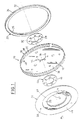
- FIG. 1 shows a set of a steering wheel engine 10 for an internal combustion engine produced in accordance with a prior state of the art.
- the flywheel 10 is substantially axial of axis A and it is intended to be fixed, on the left in Figure 1, at the rear of a crankshaft (not shown) of a vehicle heat engine.
- the flywheel 10 comprises a plate drive 12 in the form of a disc including holes 14, angularly distributed evenly around the axis A, allow the passage of screws (not shown) for fixing the flywheel 10 to the engine crankshaft.
- the drive plate 12 has a cage 16 of cylindrical axial ignition which came integrally with the drive plate 12 and which has on its periphery 18 notches 20 forming a test pattern for adjusting the ignition of the vehicle engine.
- the manufacture of the drive plate 12 comprises a stamping step on a line of presses, then a recovery stage, during which a specific machine notching performs the notches 20 on the periphery 18 of its cage 16.
- the flywheel 10 comprises, at the rear of the plate drive 12, an axial annular ring 22 of launch which has on its periphery teeth 24 which are intended to mesh with a starter pinion (not represented).
- the crown 22 is, conventionally, hooped on the drive plate 12 or is mounted to the press, then welded, on a cylindrical surface (not represented) which forms part by a rear face of the plate 12.
- the annular ring 22 has a recess circular 26 coaxial interior inside which is received with clearance, coaxial with axis A, a washer 28, also called gusset, which is flush in the rear transverse plane of the crown 22, so that a rear face 30 of the washer 28 and a rear face 32 of the crown 22 together form a flat bearing surface for a coupling member of the engine with a vehicle transmission, in particular with a clutch or shell of a turbine of a converter couple.
- the flywheel 10 comprises, at the front of the plate 12, a flywheel 34 which is fixed on a front face 36 of the drive plate 12 via screws (not shown) which pass through coaxial holes respective 38 of the flywheel 34 and 40 of the flywheel 12.
- the flywheel 34 has at least a part 35 of diameter smaller than that of the cage cylindrical 16 so that a rear face 37 of the steering wheel of inertia is supported on the front face 36 of the plate training 12
- the flywheel 34 has a circular opening 42 interior coaxial inside which is received, with a radial clearance, a washer 44 forming a gusset which is coaxial to axis A and which is the same thickness as the flywheel 34 of inertia so that a front face 46 of the washer 44 and a front face 48 of the steering wheel together form a flat surface support for a flat rear face of an element additional rotationally linked to the engine crankshaft vehicle, such as an electric machine rotor forming alternator and starter.
- This design has the main disadvantage not being able to dissociate the drive plate 12, the function is to provide the connection to the vehicle crankshaft and which, as such, could therefore ensure this connection for other engines of different types, from the ignition cage 16 which is on the contrary specific to the engine to which the flywheel motor 10 is intended.
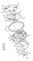
- FIGS 2 to 5 show first and second embodiments of the invention, which make it possible to remedy to these disadvantages.
- the flywheel 10 comprises at least one support 50 in the form of a disc, which, on the one hand, carries the cage 16 ignition, the launch ring 22, and an element of inertia 52, and which, on the other hand is fixed to the plate 12 to allow modular mounting of cages of ignition, launching rings and inertia elements different, each adapted to a specific engine, on a support and a common training platform.
- the steering wheel engine 10 is mounted at the end of the engine crankshaft.
- the flywheel 10 comprises successively back and forth, that is to say from the left to the right of Figures 2 and 5, a washer 54 for fixing the drive plate 12 on the support 50, the plate 12, the ignition cage 16, a spacer 56 which will be described later in more detail, the crown 22 of launch, support 50 and finally element 52 of inertia.
- the washer 54, the drive plate 12, the cage 16 ignition, the spacer 56, the crown 22, the support 50, and the inertial element 52 are cut from plates, especially steel, of adequate thickness.
- the holes coaxial 14 distributed angularly in a regular manner according to a first diameter D1 around the axis A of the flywheel 10 are practiced in the washer 54, the drive plate 12, the spacer 56, and the support 50. These holes 14 are intended allow the passage of the flywheel fixing screw 10 on the end (not shown) of the engine crankshaft.
- holes 65 coaxials distributed angularly in a regular manner according to a second diameter D2 around the axis A of the flywheel 10 are practiced in the drive plate 12, the cage 16 ignition, the support 50 and the inertia element 52 to ensure fixing the ignition cage 16, the support 50 and the inertia element 52 to each other by riveting.
- the holes 65 of the drive plate 12 are of a diameter greater than the holes 65 of the ignition cage 16, of the support 50 and of the inertia element 52 so as to allow the passage of fastening rivets 86 without these participate in the connection of the drive plate 12, it being fixed. as we will see later, by others means to the ignition cage 16, to the support 50 and to the element of inertia 52.
- the washer 54 is of a substantially annular shape and has at least one leg 60, initially radial, which extends radially outward.
- the washer 54 comprises three identical legs 60 which are located angularly at 120 degrees from each other. This provision is not limiting of the invention, and the washer 14 can include as many legs 60 as necessary to ensure adequate fixation of the drive plate 12 on the support 50.
- slits offset 64 angularly distributed evenly around axis A, are practiced in the plateau drive 12 and eccentric slots 66 similar are practiced in the support 50.
- the drive plate 12 and the support 50 have as many slots 64 and 66 as the washer 54 has legs 60. These slots are intended for cooperate with the legs 60 of the washer 54 for fixing the drive plate 12 on the support 50.
- the washer 54, the drive plate 12, the ignition cage 16, the support 50 and the spacer 56 are cut so as to include interior openings 67, 68, 70, 72, and 74 respectively, circular and coaxial to axis A.
- the respective circular openings 67, 68, 72 and 74 the washer 54, the drive plate 12, the support 50, and the spacer 56 are intended to allow for example, when assembling the flywheel 10 to the crankshaft, the passage of a shoulder with a diameter less than the diameter D1 of the crankshaft, which allows the centering of the flywheel 10.
- the opening 70 of the ignition cage 16 allows the mounting of the spacer 56.
- recesses Eccentric 53 are also produced in support 50. These recess 53 are intended to cooperate with the inertia element 52 to allow its angular position.
- a flat ring (not shown) which is intended to form the cage 16 ignition is obtained by cutting a flat plate, and the notches 20 are made on this occasion flat in this plane ring.
- the legs 60 of the washer 54 are partially folded backwards to form axial arms 62 which are eccentric with respect to axis A.
- These arms 62 are intended to cooperate with the slots 64 of the drive plate 12 and the slots 66 of the support 50 to immobilize the drive plate 12 by relative to the support 50.
- These arms 60 are in particular of a diameter greater than the diameter of the spacer 56 and less than the diameter of the opening 70 of the ignition cage 16, so that they are likely to cross this opening 70 at mounting.
- the washer 54 also includes at least one tab 76, initially radial, which is carried out during the first stage cutting, and which extends radially inward from of the opening 67 of the washer 54.
- the tab 76 of the washer 54 is folded back to extend parallel to the axis A.
- the tab 76 is eccentric with respect to axis A along the diameter of the interior opening 68 of the plate 12.
- This axial tab 76 is intended, during assembly, to be received in a complementary groove 78 of the spacer 56, which is produced during the first stage of cut out, so as to immobilize the spacer 56 in rotation by compared to the drive plate 12, and therefore compared to the support 50, via the washer 54.
- the washer 54 has a axial leg 76 but it could have a number upper legs which would be angularly arranged at regular intervals.
- the planar ring is stamped so as to form the periphery 18 of the cylindrical cage 16 which carries the notches 20 forming a target for adjusting the engine ignition.
- the inertial element 52 is stamped so as to have bosses 51 which are intended to cooperate with the eccentric recesses 53 of the support 50 in order to allow the angular position of the inertial element 52 relative to to the support 50.
- the bosses 51 of the inertia element 52 and the recesses 53 in support 50 are shown in detail in Figures 4 and 5.
- the drive plate 12 and support 50 are also stamped in a bowl shape so as to limit their axial dimensions in relation to the entire flywheel 10.
- the annular ring 22 is heat treated, for example by a quenching process, so that its teeth 24 have mechanical characteristics allowing a sufficient resistance when meshing with the pinion of the vehicle engine starter (not shown).
- crown 22 is assembled without play, for example press fit on the periphery 80 of the support 50, to which it is welded during a sixth welding step.
- the crown 22 and the support 50 then constitute a sub-assembly 82 of the steering wheel to which the remaining components of the flywheel 10 during an assembly step.
- the cage ignition 16 and the spacer 56 are interposed between the drive plate 12 and support 50 so that the respective offset lights 59, 61 and 63 of cage 16 ignition, support 50, and inertia element 52 are aligned.
- the stamped bowl shapes of the drive plate 12 and support 50 allow the drive plate 50 flush with the front face 36 of the ignition cage 16 despite the thickness of the spacer 56, this which limits the total axial size of the flywheel 10.
- the washer 54 is used to immobilize these elements.
- the axial arms 62 of the washer 54 penetrate this effect in the slots 60 of the drive plate 12, pass through the opening 70 of the ignition cage 16, and penetrate in the slots 66 of the support 50, at the same time as the tab 76 axial of the washer 54 crosses the opening 68 of the plate 12, the groove 78 of the spacer 56 and the opening 72 of the support 50.
- the ends of the arms 62 axial legs 60 are twisted around the direction substantially axial of the arms 62 so that the arms 62 are blocked on the back of a rear face 84 of the sub-assembly 82, that is to say on the back of the rear face 84 of the support 50. as shown in figure 6.
- the inertial element 52 is then placed in position by relative to the support 50 by means of its bosses 51 which penetrate in the recesses 53 opposite the support 50.
- the ignition cage 16 and the inertia element 52 are permanently assembled to support 50 using rivets 86 which pass through the holes 65 previously described.
- the flywheel can then be assembled at the end of the crankshaft using screws (not shown) passing through the holes 14 of the washer 54, of the drive plate 12, of the spacer 56, and of the support 50.
- Figure 1 there is shown a first mode of embodiment of the invention in which the element of inertia 52 is consisting of a disc 52a.
- the inertia element 52 is assembled in one piece to the support 50.
- each flyweight 52b has at least one boss 51 which is intended to enter one of the recesses 53 of the support 50 to achieve the angular positioning of the element of inertia with respect to the support 50.
- This latter embodiment is particularly advantageous because it allows, due to the reduced clearance which exists between two consecutive weights 52b, at the edge 55 junction, to more easily set up the weights on the back of the rear face 84 of the support 50.
- the inertia element 52 could consist of a stack of 52a discs, plus 52b spreaders distributed angularly, or a stack of weights 52b distributed angularly aligned or staggered, so as to adjust the inertia of element 52 as close as possible to a determined inertia allowing theoretical balancing of the engine crankshaft.
- the invention therefore advantageously makes it possible to produce a low cost modular flywheel 10.
Landscapes
- Engineering & Computer Science (AREA)
- General Engineering & Computer Science (AREA)
- Mechanical Engineering (AREA)
- Physics & Mathematics (AREA)
- Acoustics & Sound (AREA)
- Aviation & Aerospace Engineering (AREA)
- Chemical & Material Sciences (AREA)
- Combustion & Propulsion (AREA)
- Manufacturing & Machinery (AREA)
- Ignition Installations For Internal Combustion Engines (AREA)
Applications Claiming Priority (2)
| Application Number | Priority Date | Filing Date | Title |
|---|---|---|---|
| FR9911636A FR2798712B1 (fr) | 1999-09-17 | 1999-09-17 | Volant moteur modulaire |
| FR9911636 | 1999-09-17 |
Publications (1)
| Publication Number | Publication Date |
|---|---|
| EP1085234A1 true EP1085234A1 (de) | 2001-03-21 |
Family
ID=9549956
Family Applications (1)
| Application Number | Title | Priority Date | Filing Date |
|---|---|---|---|
| EP00402473A Withdrawn EP1085234A1 (de) | 1999-09-17 | 2000-09-08 | Modulares Schwungrad |
Country Status (2)
| Country | Link |
|---|---|
| EP (1) | EP1085234A1 (de) |
| FR (1) | FR2798712B1 (de) |
Cited By (4)
| Publication number | Priority date | Publication date | Assignee | Title |
|---|---|---|---|---|
| FR2818174A1 (fr) * | 2000-12-19 | 2002-06-21 | Renault | Procede de fabrication d'une cage d'allumage |
| ITVA20130039A1 (it) * | 2013-07-15 | 2015-01-16 | Fugazzotto Vittoria | Bicycle inertial bottom bracket - movimento centrale per bicicletta dotato di sistema inerziale per il recupero dell'energia cinetica spesa durante la pedalata (passaggio dal punto superiore al punto morto inferiore) |
| WO2016188521A1 (de) * | 2015-05-26 | 2016-12-01 | Schaeffler Technologies AG & Co. KG | Einmassenschwungrad |
| CN110810045A (zh) * | 2019-12-17 | 2020-02-21 | 常州格力博有限公司 | 修枝机 |
Citations (3)
| Publication number | Priority date | Publication date | Assignee | Title |
|---|---|---|---|---|
| US4650050A (en) * | 1983-05-24 | 1987-03-17 | Valeo | Starting and coupling member |
| EP0548871A1 (de) * | 1991-12-23 | 1993-06-30 | Chrysler Corporation | Fahrzeug-modulare Kupplung-Befestigungsanordnung |
| US5732810A (en) * | 1995-09-13 | 1998-03-31 | Fichtel & Sachs Ag | Friction clutch with a pulse generator |
-
1999
- 1999-09-17 FR FR9911636A patent/FR2798712B1/fr not_active Expired - Fee Related
-
2000
- 2000-09-08 EP EP00402473A patent/EP1085234A1/de not_active Withdrawn
Patent Citations (3)
| Publication number | Priority date | Publication date | Assignee | Title |
|---|---|---|---|---|
| US4650050A (en) * | 1983-05-24 | 1987-03-17 | Valeo | Starting and coupling member |
| EP0548871A1 (de) * | 1991-12-23 | 1993-06-30 | Chrysler Corporation | Fahrzeug-modulare Kupplung-Befestigungsanordnung |
| US5732810A (en) * | 1995-09-13 | 1998-03-31 | Fichtel & Sachs Ag | Friction clutch with a pulse generator |
Cited By (4)
| Publication number | Priority date | Publication date | Assignee | Title |
|---|---|---|---|---|
| FR2818174A1 (fr) * | 2000-12-19 | 2002-06-21 | Renault | Procede de fabrication d'une cage d'allumage |
| ITVA20130039A1 (it) * | 2013-07-15 | 2015-01-16 | Fugazzotto Vittoria | Bicycle inertial bottom bracket - movimento centrale per bicicletta dotato di sistema inerziale per il recupero dell'energia cinetica spesa durante la pedalata (passaggio dal punto superiore al punto morto inferiore) |
| WO2016188521A1 (de) * | 2015-05-26 | 2016-12-01 | Schaeffler Technologies AG & Co. KG | Einmassenschwungrad |
| CN110810045A (zh) * | 2019-12-17 | 2020-02-21 | 常州格力博有限公司 | 修枝机 |
Also Published As
| Publication number | Publication date |
|---|---|
| FR2798712B1 (fr) | 2001-11-16 |
| FR2798712A1 (fr) | 2001-03-23 |
Similar Documents
| Publication | Publication Date | Title |
|---|---|---|
| EP0341133B1 (de) | Torsionsschwingungsdämpfer mit elastischen Flanschen, insbesondere für Kraftfahrzeuge | |
| FR2767367A1 (fr) | Dispositif pour l'amortissement d'oscillations de rotation | |
| FR2661722A1 (fr) | Ensemble a embrayage a friction et son procede de realisation. | |
| EP0715695A1 (de) | Dämpfungsschwingrad, insbesondere für kraftfahrzeuge | |
| EP0877870B1 (de) | Reibungskupplung mit niedriger ausrückkraft | |
| EP1279828B1 (de) | Nachgiebige Kupplung zur Verbindung des Rotors einer elektischen Maschine mit der Kurbelwelle des Verbrennungsmotors eines Kraftfahrzeugs | |
| EP0972142A1 (de) | Reibungskupplungsmechanismus mit einer nachstellvorrichtung, insbesondere für kraftfahrzeuge | |
| FR2594191A1 (fr) | Embrayage a friction | |
| EP1085234A1 (de) | Modulares Schwungrad | |
| EP0770788B1 (de) | Kupplungseinheit mit verbesserten Befestigungsmitteln zur Montage des Deckels auf dem Schwungrad | |
| FR2722548A1 (fr) | Embrayage a friction comprenant un volant moteur | |
| FR2694611A1 (fr) | Dispositif de fixation d'un embrayage sur un vilebrequin. | |
| FR2817933A1 (fr) | Embrayage a friction | |
| EP1508728B1 (de) | Schaltvorrichtung, und damit ausgerüstete Baugruppe und Kraftfahrzeug | |
| FR2812703A1 (fr) | Volant moteur modulaire assemble par un procede de soudage a decharge electrique | |
| EP1681481A1 (de) | Übertragungselement mit Zentrierlager zur Bedämpfung von Schwingungen | |
| EP0725905B1 (de) | Zweimassenschwungrad | |
| EP4240988A1 (de) | Vorrichtung für eine kraftfahrzeuggetriebekette | |
| EP1331126B1 (de) | Hybridantriebssystem eines Kraftfahrzeugs mit elastischer Kupplungsvorrichtung zwischen dem Rotor der reversiblen elektrischen Maschine und der Antriebswelle des Schaltgetriebes des Kraftfahrzeugs | |
| EP0678173B2 (de) | Kupplungseinheit wobei der kupplungsdeckel durch eine bajonettverbindung auf das schwungrad montiert ist | |
| FR2712362A1 (fr) | Module d'embrayage à serrage élastique du diaphragme et mécanisme correspondant. | |
| EP3838644A1 (de) | Hybrid modul bestimmt für einen antriebsstrang von einem fahrzeug | |
| FR2495715A1 (fr) | Dispositif d'embrayage pour mise en marche et changement de rapport de transmission | |
| EP0688405A1 (de) | Doppelter torsionsschwingungsdämpfer, insbesondere für kraftfahrzeuge | |
| EP0780588B1 (de) | Kupplungseinheit mit einem verzahnten Targetring |
Legal Events
| Date | Code | Title | Description |
|---|---|---|---|
| PUAI | Public reference made under article 153(3) epc to a published international application that has entered the european phase |
Free format text: ORIGINAL CODE: 0009012 |
|
| AK | Designated contracting states |
Kind code of ref document: A1 Designated state(s): DE ES GB IT Kind code of ref document: A1 Designated state(s): AT BE CH CY DE DK ES FI FR GB GR IE IT LI LU MC NL PT SE |
|
| AX | Request for extension of the european patent |
Free format text: AL;LT;LV;MK;RO;SI |
|
| 17P | Request for examination filed |
Effective date: 20011008 |
|
| AKX | Designation fees paid |
Free format text: AT BE CH CY DE DK ES FI FR GB GR IE IT LI LU MC NL PT SE |
|
| GRAG | Despatch of communication of intention to grant |
Free format text: ORIGINAL CODE: EPIDOS AGRA |
|
| RBV | Designated contracting states (corrected) |
Designated state(s): DE ES GB IT |
|
| 17Q | First examination report despatched |
Effective date: 20020619 |
|
| RAP1 | Party data changed (applicant data changed or rights of an application transferred) |
Owner name: RENAULT S.A.S. |
|
| STAA | Information on the status of an ep patent application or granted ep patent |
Free format text: STATUS: THE APPLICATION HAS BEEN WITHDRAWN |
|
| 18W | Application withdrawn |
Effective date: 20021129 |