EP1087406A1 - Assemblage de combustible avec des barreaux de combusitble pour réacteur à eau bouillante - Google Patents
Assemblage de combustible avec des barreaux de combusitble pour réacteur à eau bouillante Download PDFInfo
- Publication number
- EP1087406A1 EP1087406A1 EP00120030A EP00120030A EP1087406A1 EP 1087406 A1 EP1087406 A1 EP 1087406A1 EP 00120030 A EP00120030 A EP 00120030A EP 00120030 A EP00120030 A EP 00120030A EP 1087406 A1 EP1087406 A1 EP 1087406A1
- Authority
- EP
- European Patent Office
- Prior art keywords
- fuel
- area
- section
- corner
- fuel element
- Prior art date
- Legal status (The legal status is an assumption and is not a legal conclusion. Google has not performed a legal analysis and makes no representation as to the accuracy of the status listed.)
- Withdrawn
Links
- 239000000446 fuel Substances 0.000 title claims abstract description 204
- XLYOFNOQVPJJNP-UHFFFAOYSA-N water Substances O XLYOFNOQVPJJNP-UHFFFAOYSA-N 0.000 title claims abstract description 37
- 238000009835 boiling Methods 0.000 title abstract description 8
- 125000006850 spacer group Chemical group 0.000 claims description 4
- 239000003758 nuclear fuel Substances 0.000 description 15
- 239000002826 coolant Substances 0.000 description 11
- 238000009826 distribution Methods 0.000 description 7
- 230000002349 favourable effect Effects 0.000 description 6
- 238000011161 development Methods 0.000 description 5
- 230000018109 developmental process Effects 0.000 description 5
- 239000007788 liquid Substances 0.000 description 3
- 230000009467 reduction Effects 0.000 description 3
- 230000005514 two-phase flow Effects 0.000 description 3
- 238000005253 cladding Methods 0.000 description 2
- 238000010521 absorption reaction Methods 0.000 description 1
- 206010000496 acne Diseases 0.000 description 1
- 230000000712 assembly Effects 0.000 description 1
- 238000000429 assembly Methods 0.000 description 1
- 230000009286 beneficial effect Effects 0.000 description 1
- 230000008901 benefit Effects 0.000 description 1
- 230000015572 biosynthetic process Effects 0.000 description 1
- 230000008859 change Effects 0.000 description 1
- 239000000498 cooling water Substances 0.000 description 1
- 230000000694 effects Effects 0.000 description 1
- 230000008030 elimination Effects 0.000 description 1
- 238000003379 elimination reaction Methods 0.000 description 1
- 210000003746 feather Anatomy 0.000 description 1
- 230000004907 flux Effects 0.000 description 1
- 230000006872 improvement Effects 0.000 description 1
- 239000000463 material Substances 0.000 description 1
- 239000002574 poison Substances 0.000 description 1
- 231100000614 poison Toxicity 0.000 description 1
Images


Classifications
-
- G—PHYSICS
- G21—NUCLEAR PHYSICS; NUCLEAR ENGINEERING
- G21C—NUCLEAR REACTORS
- G21C3/00—Reactor fuel elements and their assemblies; Selection of substances for use as reactor fuel elements
- G21C3/30—Assemblies of a number of fuel elements in the form of a rigid unit
- G21C3/32—Bundles of parallel pin-, rod-, or tube-shaped fuel elements
- G21C3/326—Bundles of parallel pin-, rod-, or tube-shaped fuel elements comprising fuel elements of different composition; comprising, in addition to the fuel elements, other pin-, rod-, or tube-shaped elements, e.g. control rods, grid support rods, fertile rods, poison rods or dummy rods
- G21C3/328—Relative disposition of the elements in the bundle lattice
-
- G—PHYSICS
- G21—NUCLEAR PHYSICS; NUCLEAR ENGINEERING
- G21C—NUCLEAR REACTORS
- G21C3/00—Reactor fuel elements and their assemblies; Selection of substances for use as reactor fuel elements
- G21C3/30—Assemblies of a number of fuel elements in the form of a rigid unit
- G21C3/32—Bundles of parallel pin-, rod-, or tube-shaped fuel elements
- G21C3/322—Means to influence the coolant flow through or around the bundles
-
- Y—GENERAL TAGGING OF NEW TECHNOLOGICAL DEVELOPMENTS; GENERAL TAGGING OF CROSS-SECTIONAL TECHNOLOGIES SPANNING OVER SEVERAL SECTIONS OF THE IPC; TECHNICAL SUBJECTS COVERED BY FORMER USPC CROSS-REFERENCE ART COLLECTIONS [XRACs] AND DIGESTS
- Y02—TECHNOLOGIES OR APPLICATIONS FOR MITIGATION OR ADAPTATION AGAINST CLIMATE CHANGE
- Y02E—REDUCTION OF GREENHOUSE GAS [GHG] EMISSIONS, RELATED TO ENERGY GENERATION, TRANSMISSION OR DISTRIBUTION
- Y02E30/00—Energy generation of nuclear origin
- Y02E30/30—Nuclear fission reactors
Definitions
- the invention relates to a fuel element with practically parallel to a fuel element axis and practically perpendicular to one polygonal internal cross section perpendicular to the fuel element axis arranged fuel rods. It is in a first Area the ratio of the free area of the inner cross section to the area penetrated by fuel rods less than in a second area.
- thermohydraulics and the neutron economy for a fuel element the distance between the fuel rods - especially in relation to the radius of the cladding tube - variable, but constant for a fuel assembly can be set (EP 0 373 418 B1). This serves in particular reduction in pressure loss, improvement the moderation ratio and the reduction of Neutron absorption through the structural material. It is an advantage if the situation is as homogeneous as possible thermohydraulics and neutron economy over the Cross section of the reactor core and in particular over the cross section of a fuel assembly is reachable.
- thermohydraulic one and neutron economic properties of Reactor core have a variety of inhomogeneities and asymmetries on.
- Such an inhomogeneity or asymmetry can, for example in a pressurized water fuel assembly by the arrangement of Control rods, instrumentation tubes or other tubes without Fuel.
- a boiling water reactor fuel element can, for example, the arrangement of control rods between neighboring fuel assemblies the cause of one anisotropic neutron flux.
- Inhomogeneities and asymmetries can with light water reactors and / or light water reactor fuel elements for example, through a distribution of differently enriched and / or with neutron poison provided fuel rods over the cross section of the Fuel element arise.
- thermohydraulics and / or neutron economy essentially concern centrosymmetric distributions of fuel rod distances and / or sizes, at most with local limited deviations from the centrosymmetry that lead to Elimination of strongly local influences - for example at the edge of a boiling water reactor fuel element a control stick - serve.
- the invention is based on the surprising consideration that improve a fuel assembly of the type mentioned leaves.
- the object of the invention is a light water reactor fuel assembly indicate that both improved thermohydraulics and also has an improved neutron economy.
- This object is achieved by a fuel assembly type mentioned solved in that the first area forms a first corner of the inner cross-section and other corners of the inner cross section are formed by the second region. There is also a distance between the outer surfaces each two adjacent fuel rods - in a direction from starting from the first corner of the fuel assembly - increasing monotonously. This is particularly along a diagonal and / or one side of the inner cross section.
- a fuel rod is practically perpendicular to the polygonal one Arranged internal cross section and penetrates this with the Cross-sectional area of the fuel rod. This is a free, the Cooling water accessible area of the inner cross section and a surface of the inner cross section penetrated by fuel rods.
- the invention is based on the knowledge that it The solution to the task is favorable, a redistribution of the coolant and moderator flow in a light water reactor fuel element of the type mentioned in the first section towards the second area, which is caused by a Reduction of the free area in the first area and the arrangement of the first area in the first corner of the inner cross section reached in the fuel element mentioned above becomes.
- This is beneficial with a coolant flow that is practically a two-phase flow, i.e. a flow with a high proportion of steam (e.g. up to about 40% to 50%).
- the first area a distance between the outer surfaces of two neighboring fuel rods on average less than in the second area. Above all, the average is the distance the fuel rods in the first area are lower than in the second area. In this way, the coolant (and mainly the proportion of steam in the coolant) first area pushed into the second area.
- the distance between the outer surfaces each two adjacent fuel rods in the manner mentioned above is variable. It is also advantageous that the fuel rods have an equal center-to-center distance and the diameter the fuel rods are variable. For example, the Fuel rods in the first area have a larger fuel rod diameter than in the second area.
- a relatively small distance between its outer surface and the outer surface of a second have adjacent fuel rods on the diagonal.
- the distance the outer surface of the second fuel rod on the diagonal to the outer surface of a third adjacent fuel rod the diagonal can then be the same size or larger than the distance between the outer surfaces of the first and the second fuel rod. It is particularly advantageous if the Distance between two adjacent fuel rods of the first corner of the fuel assembly starting along one Direction corresponding to a linear, convex or concave Function of the path covered along the direction increases. In this way, the distance between the outer surfaces the penultimate fuel rod and the last fuel rod opposite the diagonal near the first corner Corner greater than the distance between the outer surfaces of the first and second fuel rods on the diagonal.
- the arrangement of the fuel rods is over the inner cross-section practically mirror-symmetrical to one Diagonal of the inner cross section starting from the first corner.
- it turns out to be practically square Internal cross section as advantageous. But it is for example also possible that a hexagonal inner cross section is present.
- the central axis is favorably of the fuel bundle built up from fuel rods laterally opposite be offset from the center of the inner cross-section and its edge can be from a first from the first corner outgoing side have a greater distance than from a second side that does not start from the first corner.
- a fuel bundle can thus in the manner just mentioned be arranged so that it is the inner cross section of a fuel assembly enforced off-center.
- a fuel assembly according to a further development the invention a practically parallel to the fuel rods Water pipe arrangement on.
- it can also be a fuel assembly according to US 5,289,514 act or a fuel element according to the European Patent EP 0 224 728 B1.
- a fuel assembly with a water pipe which penetrates the inner cross-section centrally.
- a water pipe arrangement does not always have to be from a single round or rectangular water pipe exist, much more are others (e.g. cruciform) cross sections or arrangements with several Pipes possible (compare e.g.
- the first area in particular is polygonal, and adjoins with a corner opposite the first corner a water pipe arrangement.
- the first area is advantageous square.
- the second area is also advantageous polygonal and has a portion that one of the first corner forms opposite corner.
- Partial area is advantageous the ratio of the free area of the inner cross-section to that of fuel rods Area larger than in another section with a similar one Area of the inner cross section.
- the first area essentially on the diagonal arranged that side of the water pipe arrangement, which one smaller distance of the central axis of the water pipe arrangement to the edge of the inner cross section.
- the second area includes practically the remaining internal cross section of the fuel assembly, said sub-area in which the ratio of free area of the internal cross-section to that of fuel rods enforced area is largest, essentially on the Diagonals and arranged on that side of the water pipe arrangement is on the central axis of the water pipe assembly has the greater distance from the edge of the inner cross section.
- the fuel rods are practically parallel to each other Rows and columns practically perpendicular to the rows arranged.
- a fuel rod is held in the middle of the stitch.
- the middle opening of a Mesh is essentially the total area of the mesh size by the number of stitches in each Area. In particular, there are the smallest Stitches in the first area and the largest stitches in the second Area.
- the mesh size (i.e. the opening) is therefore favorable one stitch) each of the arrangement of the fuel rods in the adapted the first area and the second area.
- Advantageous is such an adjustment by appropriate spacer elements - for example pimples or feathers - added.
- a fuel assembly 1 in FIG. 1 is a section across the fuel element axis with fuel rods and spacers shown.
- the fuel rods B are practical arranged parallel to a fuel element axis. This The axis is perpendicular to a polygonal inner cross section 7, which practically from the inner edge in this embodiment of a fuel assembly box 9 is bordered.
- the fuel rods B are thus practically perpendicular to that of this Embodiment arranged square inner cross section 7 and pass through the inner cross section 7 on a surface which given by the cross section Q of a fuel rod B. is.
- the sum of all cross sections Q1 in the first area 3 gives the area penetrated by fuel rods B1.
- the remaining area forms the free area of the first area 3.
- the sum of all cross sections Q2 results from that of fuel rods B2 penetrated area in the second area 5.
- the first area 3 and the second area 5 form together practically the inner cross section 7.
- the first area 3 forms practically a first corner 11 of the inner cross section 7.
- the other corners 12, 13 of the inner cross section 7, in particular the corner 12 opposite the first corner 11, are from the second area 5 is formed. Since in the embodiment shown a distance D between the outer surfaces A in each case along two adjacent fuel rods B. the diagonal W of the inner cross section 7 of the fuel assembly 1 starting from the first corner 11 of the fuel assembly 1 to the opposite one Corner 12 increases monotonously, is in the first Area 3 the ratio of the free area of the inner cross section 7 to the area traversed by fuel rods B1 than in a second area 5.
- a distance B1 between the outer surfaces A1 of two adjacent fuel rods B1 is smaller on average than a distance B2 between the outer surfaces A2 of two adjacent fuel rods B2 in the second region 5.
- the cross section Q of a fuel rod B is over the entire inner cross section 7 of the fuel assembly 1 constant.
- the distance D as a function of the path even increases linearly in this embodiment.
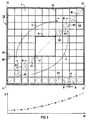
- Fuel assembly 1A takes according to the graph in Figure 2 the distance D between the outer surfaces A of two adjacent ones Fuel rods B in one direction from the first corner 11 of the fuel assembly 1 starting from the opposite corner 12 not strictly monotonous, but only monotonous.
- the distance D has the constant value D1 and then abruptly increases at the border to a second Area 5A in which the distance D is also a constant but has greater value D2.
- the distance D1 matches that average distance between the outer surfaces A1 two each of adjacent fuel rods B1 in the first region 3A.
- distance D2 agrees with the mean distance between the outer surfaces A2 of two adjacent fuel rods 32 in second area 5A. Both in the embodiment 1 and in FIG. 2 all have fuel rods B of the fuel assembly 1 has the same cross section Q and thus the same diameter.
- FIG. 2 shows an embodiment of a fuel assembly 1A in essentially with a fuel assembly 15 with 10 x 10 positions for fuel rods B - again as a cut across Fuel axis.
- the illustration in FIG. 2 applies equally for a pressurized water reactor fuel element.
- a corresponding one Fuel bundle would be in a pressurized water reactor fuel assembly for example 17 x 17 or 18 x 18 fuel rods B comprise, with control rods arranged between the fuel rods B.
- It can be, for example, a fuel assembly can be assumed according to US Pat. No. 4,849,161, whereby the arrangement of the fuel rods in the manner according to the invention is modified - in a section, for example, as in Figure 2.
- Fuel assembly 1B takes the distance D between the outer surfaces two adjacent fuel rods B each from the first Corner 11 of the fuel assembly 1 starting from a corner 12 along the diagonal W of the inner cross section 7 accordingly a convex function depending on the path along the Diagonals W zu (graphic in Figure 3).
- 1B is the center point distance M between two neighboring ones Fuel rods B1 in the first area 3B the same as the center point distance M of two adjacent fuel rods B2 in the second region 5B, however, the cross section has Q1 a larger fuel rod B1 in the first area 3B Value as the cross section Q2 of a fuel rod B2 in the second area 5B. This leads to that in the graphic in Figure 3 convex increase in the distance D along the diagonal W of the inner cross section 7 in the embodiment 1B of the fuel assembly.
- 1A and 1B of a fuel assembly is the arrangement of each Fuel rods 3 practically mirror-symmetrical over the inner cross-section 7 to one from the first corner 11 to an opposite one Corner 12 going diagonal W of the inner cross section 7 of the respective embodiment 1, 1A, 1B, wherein the inner cross section 7 is practically square.
- the embodiment of a fuel assembly 1 shown in FIG. 3 also has a to the fuel rods B of this embodiment practically parallel water pipe R.
- the first area 3B is a first Forms corner 11 of the inner cross section and in particular with a inner corner 17, which lies opposite the first corner 11, adjacent to the water pipe R is the open flow cross section in the first area 3B much less than in the second area 5B and in particular in a partial area 19 of the second area 5B.
- the sub-area 19 has the same footprint as the first area 3B. But since that Ratio of the free area of the inner cross section 7 to that Area penetrated by fuel rods B2 is larger in partial area 19 than in the first area 3B, is the flow area in the partial area 19 larger than in the first Area 3.
- FIG 4 shows a further embodiment of a Fuel assembly 1C.
- the fuel assembly 1C a water pipe R located off-center of the fuel assembly axis on.
- the fuel assembly 15 is along as a whole the diagonal W of the inner cross section 7 of the fuel assembly 1 moved towards the first area or the first corner 11, so moved away from the opposite corner 12. This measure leads in this embodiment to the fact that in the first area 3C the ratio of the free area of the Internal cross-section 7 to that of fuel rods B1 Area is less than in the second area 5C.
Landscapes
- Physics & Mathematics (AREA)
- Engineering & Computer Science (AREA)
- Plasma & Fusion (AREA)
- General Engineering & Computer Science (AREA)
- High Energy & Nuclear Physics (AREA)
- Monitoring And Testing Of Nuclear Reactors (AREA)
- Liquid Carbonaceous Fuels (AREA)
- Spray-Type Burners (AREA)
Applications Claiming Priority (2)
| Application Number | Priority Date | Filing Date | Title |
|---|---|---|---|
| DE19945902 | 1999-09-24 | ||
| DE19945902 | 1999-09-24 |
Publications (1)
| Publication Number | Publication Date |
|---|---|
| EP1087406A1 true EP1087406A1 (fr) | 2001-03-28 |
Family
ID=7923233
Family Applications (1)
| Application Number | Title | Priority Date | Filing Date |
|---|---|---|---|
| EP00120030A Withdrawn EP1087406A1 (fr) | 1999-09-24 | 2000-09-14 | Assemblage de combustible avec des barreaux de combusitble pour réacteur à eau bouillante |
Country Status (4)
| Country | Link |
|---|---|
| US (1) | US6600799B1 (fr) |
| EP (1) | EP1087406A1 (fr) |
| JP (1) | JP2001116874A (fr) |
| TW (1) | TW529037B (fr) |
Cited By (1)
| Publication number | Priority date | Publication date | Assignee | Title |
|---|---|---|---|---|
| WO2007093313A1 (fr) * | 2006-02-18 | 2007-08-23 | Areva Np Gmbh | ELEMENT DE COMBUSTIble POUR REACTEUR NUCLEAIRE A EAU SOUS PRESSION |
Families Citing this family (1)
| Publication number | Priority date | Publication date | Assignee | Title |
|---|---|---|---|---|
| CN103093839B (zh) * | 2013-01-22 | 2016-01-06 | 中科华核电技术研究院有限公司 | 轻水反应堆的燃料组件 |
Citations (3)
| Publication number | Priority date | Publication date | Assignee | Title |
|---|---|---|---|---|
| US4495136A (en) * | 1982-05-11 | 1985-01-22 | Westinghouse Electric Corp. | Maximum power capability blanket for nuclear reactors |
| US5434898A (en) * | 1994-03-14 | 1995-07-18 | Siemens Power Corporation | Nuclear fuel assembly |
| US5572560A (en) * | 1995-06-29 | 1996-11-05 | Siemens Power Corporation | BWR fuel assembly having fuel rods with variable fuel rod pitches |
Family Cites Families (14)
| Publication number | Priority date | Publication date | Assignee | Title |
|---|---|---|---|---|
| FR1276233A (fr) | 1960-03-14 | 1961-11-17 | Gen Nuclear Engineering Co | Perfectionnements apportés à des réacteurs nucléaires |
| SE321529B (fr) | 1966-10-06 | 1970-03-09 | Asea Ab | |
| SE334955B (fr) | 1970-06-18 | 1971-05-10 | Asea Atom Ab | |
| SE423760B (sv) | 1980-11-05 | 1982-05-24 | Asea Atom Ab | Kernbrenslepatron |
| JPS61223582A (ja) | 1985-03-29 | 1986-10-04 | 株式会社日立製作所 | 原子炉用燃料集合体 |
| DE3540466A1 (de) * | 1985-11-14 | 1987-05-21 | Kraftwerk Union Ag | Kernreaktorbrennelement |
| US4849161A (en) | 1987-02-19 | 1989-07-18 | Advanced Nuclear Fuels Corp. | Debris-resistant fuel assembly |
| JPH0636046B2 (ja) * | 1988-06-08 | 1994-05-11 | 株式会社日立製作所 | 燃料集合体,燃料スペーサ及び原子炉の初装荷炉心 |
| EP0364623B1 (fr) | 1988-10-21 | 1994-06-29 | Siemens Aktiengesellschaft | Elément combustible, notamment pour réacteur à eau pressurisée |
| DE8815433U1 (de) | 1988-12-12 | 1989-02-23 | Siemens AG, 1000 Berlin und 8000 München | Brennstab für ein Brennelement eines Druckwasser-Kernreaktors |
| US5149495A (en) | 1990-05-24 | 1992-09-22 | General Electric Company | Water rod for nuclear reactor and method for providing and using same |
| EP0549639B1 (fr) | 1990-09-18 | 1995-11-15 | Siemens Aktiengesellschaft | Element combustible pour reacteur a eau bouillante presentant un support compose d'elements standardises |
| US5383229A (en) | 1992-01-08 | 1995-01-17 | Hitachi, Ltd. | Fuel assembly and reactor core |
| DE4327001A1 (de) | 1993-08-11 | 1995-02-16 | Siemens Ag | Brennelement für einen Siedewasserreaktor mit einstellbarem Bypass |
-
2000
- 2000-09-14 EP EP00120030A patent/EP1087406A1/fr not_active Withdrawn
- 2000-09-22 TW TW089119639A patent/TW529037B/zh not_active IP Right Cessation
- 2000-09-22 JP JP2000289016A patent/JP2001116874A/ja active Pending
- 2000-09-25 US US09/668,702 patent/US6600799B1/en not_active Expired - Fee Related
Patent Citations (3)
| Publication number | Priority date | Publication date | Assignee | Title |
|---|---|---|---|---|
| US4495136A (en) * | 1982-05-11 | 1985-01-22 | Westinghouse Electric Corp. | Maximum power capability blanket for nuclear reactors |
| US5434898A (en) * | 1994-03-14 | 1995-07-18 | Siemens Power Corporation | Nuclear fuel assembly |
| US5572560A (en) * | 1995-06-29 | 1996-11-05 | Siemens Power Corporation | BWR fuel assembly having fuel rods with variable fuel rod pitches |
Cited By (2)
| Publication number | Priority date | Publication date | Assignee | Title |
|---|---|---|---|---|
| WO2007093313A1 (fr) * | 2006-02-18 | 2007-08-23 | Areva Np Gmbh | ELEMENT DE COMBUSTIble POUR REACTEUR NUCLEAIRE A EAU SOUS PRESSION |
| US8345815B2 (en) | 2006-02-18 | 2013-01-01 | Areva Np Gmbh | Fuel assembly for a pressurized-water nuclear reactor |
Also Published As
| Publication number | Publication date |
|---|---|
| JP2001116874A (ja) | 2001-04-27 |
| TW529037B (en) | 2003-04-21 |
| US6600799B1 (en) | 2003-07-29 |
Similar Documents
| Publication | Publication Date | Title |
|---|---|---|
| DE3887230T2 (de) | Abstandhaltergitter für ein Kernbrennstabbündel. | |
| DE3844595C2 (fr) | ||
| DE68915709T2 (de) | Trümmerfängerabstandshalter mit Haltefedern. | |
| DE3022687C2 (fr) | ||
| DE69502864T2 (de) | Kernbrennstoffbundel | |
| DE2742939C3 (de) | Brennstoffanordnung in einem Siedewasserreaktor | |
| DE3325749A1 (de) | Abstandshalter fuer eine kernbrennstoffeinheit | |
| DE69301325T2 (de) | Abstandshalter mit niedrigem Druckverlust für Kernbrennstabbündel | |
| EP0364623B1 (fr) | Elément combustible, notamment pour réacteur à eau pressurisée | |
| DE69209401T2 (de) | Mit Brennstababstandshalter versehenes Siedewasserreaktorbrennstabbündel | |
| DE69502452T2 (de) | Brennstabbündelabstandshalter mit Fahnen zur Strömungsablenkung | |
| DE69117017T2 (de) | Abstandshalter aus Hülsen mit einer selbstpositionierenden Feder | |
| DE69718316T2 (de) | Kernbrennstoffeinheit | |
| DE3854986T2 (de) | Brennstabbündel | |
| DE2647000C3 (de) | Abstandshaltegitter für Brennelemente | |
| DE3802848A1 (de) | Brennelementbuendel fuer einen kernreaktor | |
| CH679960A5 (fr) | ||
| DE68903892T2 (de) | Mischgitter mit ablenkfahnen fuer kernstabbuendel. | |
| DE3877230T2 (de) | Kernbrennstabbuendel. | |
| DE3901504C2 (fr) | ||
| DE69312615T2 (de) | Spaltzone für Siedewasserkernreaktor | |
| DE3407163A1 (de) | Brennstab-abstandshaltegitter fuer kernbrennelemente | |
| DE69607213T2 (de) | Brennstabbündel für siedewasserreaktor | |
| DE1564697C3 (de) | Durchmischungsfahnen für das flüssige Kühlmittel von Kernreaktoren | |
| EP1087406A1 (fr) | Assemblage de combustible avec des barreaux de combusitble pour réacteur à eau bouillante |
Legal Events
| Date | Code | Title | Description |
|---|---|---|---|
| PUAI | Public reference made under article 153(3) epc to a published international application that has entered the european phase |
Free format text: ORIGINAL CODE: 0009012 |
|
| AK | Designated contracting states |
Kind code of ref document: A1 Designated state(s): CH DE ES FI LI SE |
|
| AX | Request for extension of the european patent |
Free format text: AL;LT;LV;MK;RO;SI |
|
| 17P | Request for examination filed |
Effective date: 20010419 |
|
| RAP1 | Party data changed (applicant data changed or rights of an application transferred) |
Owner name: FRAMATOME ANP GMBH |
|
| AKX | Designation fees paid |
Free format text: CH DE ES FI LI SE |
|
| 17Q | First examination report despatched |
Effective date: 20050411 |
|
| RAP1 | Party data changed (applicant data changed or rights of an application transferred) |
Owner name: AREVA NP GMBH |
|
| STAA | Information on the status of an ep patent application or granted ep patent |
Free format text: STATUS: THE APPLICATION HAS BEEN WITHDRAWN |
|
| 18W | Application withdrawn |
Effective date: 20061129 |