EP1089019A1 - Linearstellglied - Google Patents
Linearstellglied Download PDFInfo
- Publication number
- EP1089019A1 EP1089019A1 EP00118491A EP00118491A EP1089019A1 EP 1089019 A1 EP1089019 A1 EP 1089019A1 EP 00118491 A EP00118491 A EP 00118491A EP 00118491 A EP00118491 A EP 00118491A EP 1089019 A1 EP1089019 A1 EP 1089019A1
- Authority
- EP
- European Patent Office
- Prior art keywords
- hollow shaft
- spindle
- shaft rotor
- linear actuator
- actuator according
- Prior art date
- Legal status (The legal status is an assumption and is not a legal conclusion. Google has not performed a legal analysis and makes no representation as to the accuracy of the status listed.)
- Granted
Links
- 125000006850 spacer group Chemical group 0.000 claims description 6
- OKTJSMMVPCPJKN-UHFFFAOYSA-N Carbon Chemical compound [C] OKTJSMMVPCPJKN-UHFFFAOYSA-N 0.000 claims description 3
- 229910002804 graphite Inorganic materials 0.000 claims description 3
- 239000010439 graphite Substances 0.000 claims description 3
- 239000002184 metal Substances 0.000 claims description 3
- 238000003466 welding Methods 0.000 description 3
- 230000007659 motor function Effects 0.000 description 2
- POIUWJQBRNEFGX-XAMSXPGMSA-N cathelicidin Chemical compound C([C@@H](C(=O)N[C@@H](CCCNC(N)=N)C(=O)N[C@@H](CCCCN)C(=O)N[C@@H](CO)C(=O)N[C@@H](CCCCN)C(=O)N[C@@H](CCC(O)=O)C(=O)N[C@@H](CCCCN)C(=O)N[C@@H]([C@@H](C)CC)C(=O)NCC(=O)N[C@@H](CCCCN)C(=O)N[C@@H](CCC(O)=O)C(=O)N[C@@H](CC=1C=CC=CC=1)C(=O)N[C@@H](CCCCN)C(=O)N[C@@H](CCCNC(N)=N)C(=O)N[C@@H]([C@@H](C)CC)C(=O)N[C@@H](C(C)C)C(=O)N[C@@H](CCC(N)=O)C(=O)N[C@@H](CCCNC(N)=N)C(=O)N[C@@H]([C@@H](C)CC)C(=O)N[C@@H](CCCCN)C(=O)N[C@@H](CC(O)=O)C(=O)N[C@@H](CC=1C=CC=CC=1)C(=O)N[C@@H](CC(C)C)C(=O)N[C@@H](CCCNC(N)=N)C(=O)N[C@@H](CC(N)=O)C(=O)N[C@@H](CC(C)C)C(=O)N[C@@H](C(C)C)C(=O)N1[C@@H](CCC1)C(=O)N[C@@H](CCCNC(N)=N)C(=O)N[C@@H]([C@@H](C)O)C(=O)N[C@@H](CCC(O)=O)C(=O)N[C@@H](CO)C(O)=O)NC(=O)[C@H](CC=1C=CC=CC=1)NC(=O)[C@H](CC(O)=O)NC(=O)CNC(=O)[C@H](CC(C)C)NC(=O)[C@@H](N)CC(C)C)C1=CC=CC=C1 POIUWJQBRNEFGX-XAMSXPGMSA-N 0.000 description 1
- 230000006735 deficit Effects 0.000 description 1
- 230000000694 effects Effects 0.000 description 1
- 230000006870 function Effects 0.000 description 1
- 238000010438 heat treatment Methods 0.000 description 1
- 230000003993 interaction Effects 0.000 description 1
- 230000005405 multipole Effects 0.000 description 1
- 238000005096 rolling process Methods 0.000 description 1
Images
Classifications
-
- B—PERFORMING OPERATIONS; TRANSPORTING
- B23—MACHINE TOOLS; METAL-WORKING NOT OTHERWISE PROVIDED FOR
- B23K—SOLDERING OR UNSOLDERING; WELDING; CLADDING OR PLATING BY SOLDERING OR WELDING; CUTTING BY APPLYING HEAT LOCALLY, e.g. FLAME CUTTING; WORKING BY LASER BEAM
- B23K11/00—Resistance welding; Severing by resistance heating
- B23K11/30—Features relating to electrodes
- B23K11/31—Electrode holders and actuating devices therefor
-
- B—PERFORMING OPERATIONS; TRANSPORTING
- B23—MACHINE TOOLS; METAL-WORKING NOT OTHERWISE PROVIDED FOR
- B23K—SOLDERING OR UNSOLDERING; WELDING; CLADDING OR PLATING BY SOLDERING OR WELDING; CUTTING BY APPLYING HEAT LOCALLY, e.g. FLAME CUTTING; WORKING BY LASER BEAM
- B23K11/00—Resistance welding; Severing by resistance heating
- B23K11/30—Features relating to electrodes
- B23K11/31—Electrode holders and actuating devices therefor
- B23K11/311—Electrode holders and actuating devices therefor the actuating device comprising an electric motor
-
- B—PERFORMING OPERATIONS; TRANSPORTING
- B23—MACHINE TOOLS; METAL-WORKING NOT OTHERWISE PROVIDED FOR
- B23K—SOLDERING OR UNSOLDERING; WELDING; CLADDING OR PLATING BY SOLDERING OR WELDING; CUTTING BY APPLYING HEAT LOCALLY, e.g. FLAME CUTTING; WORKING BY LASER BEAM
- B23K11/00—Resistance welding; Severing by resistance heating
- B23K11/30—Features relating to electrodes
- B23K11/31—Electrode holders and actuating devices therefor
- B23K11/314—Spot welding guns, e.g. mounted on robots
- B23K11/315—Spot welding guns, e.g. mounted on robots with one electrode moving on a linear path
-
- F—MECHANICAL ENGINEERING; LIGHTING; HEATING; WEAPONS; BLASTING
- F16—ENGINEERING ELEMENTS AND UNITS; GENERAL MEASURES FOR PRODUCING AND MAINTAINING EFFECTIVE FUNCTIONING OF MACHINES OR INSTALLATIONS; THERMAL INSULATION IN GENERAL
- F16H—GEARING
- F16H25/00—Gearings comprising primarily only cams, cam-followers and screw-and-nut mechanisms
- F16H25/18—Gearings comprising primarily only cams, cam-followers and screw-and-nut mechanisms for conveying or interconverting oscillating or reciprocating motions
- F16H25/20—Screw mechanisms
-
- F—MECHANICAL ENGINEERING; LIGHTING; HEATING; WEAPONS; BLASTING
- F16—ENGINEERING ELEMENTS AND UNITS; GENERAL MEASURES FOR PRODUCING AND MAINTAINING EFFECTIVE FUNCTIONING OF MACHINES OR INSTALLATIONS; THERMAL INSULATION IN GENERAL
- F16H—GEARING
- F16H25/00—Gearings comprising primarily only cams, cam-followers and screw-and-nut mechanisms
- F16H25/18—Gearings comprising primarily only cams, cam-followers and screw-and-nut mechanisms for conveying or interconverting oscillating or reciprocating motions
- F16H25/20—Screw mechanisms
- F16H25/24—Elements essential to such mechanisms, e.g. screws, nuts
-
- H—ELECTRICITY
- H02—GENERATION; CONVERSION OR DISTRIBUTION OF ELECTRIC POWER
- H02K—DYNAMO-ELECTRIC MACHINES
- H02K7/00—Arrangements for handling mechanical energy structurally associated with dynamo-electric machines, e.g. structural association with mechanical driving motors or auxiliary dynamo-electric machines
- H02K7/06—Means for converting reciprocating motion into rotary motion or vice versa
-
- H—ELECTRICITY
- H02—GENERATION; CONVERSION OR DISTRIBUTION OF ELECTRIC POWER
- H02K—DYNAMO-ELECTRIC MACHINES
- H02K7/00—Arrangements for handling mechanical energy structurally associated with dynamo-electric machines, e.g. structural association with mechanical driving motors or auxiliary dynamo-electric machines
- H02K7/08—Structural association with bearings
- H02K7/083—Structural association with bearings radially supporting the rotary shaft at both ends of the rotor
-
- F—MECHANICAL ENGINEERING; LIGHTING; HEATING; WEAPONS; BLASTING
- F16—ENGINEERING ELEMENTS AND UNITS; GENERAL MEASURES FOR PRODUCING AND MAINTAINING EFFECTIVE FUNCTIONING OF MACHINES OR INSTALLATIONS; THERMAL INSULATION IN GENERAL
- F16H—GEARING
- F16H25/00—Gearings comprising primarily only cams, cam-followers and screw-and-nut mechanisms
- F16H25/18—Gearings comprising primarily only cams, cam-followers and screw-and-nut mechanisms for conveying or interconverting oscillating or reciprocating motions
- F16H25/20—Screw mechanisms
- F16H2025/2062—Arrangements for driving the actuator
- F16H2025/2075—Coaxial drive motors
-
- F—MECHANICAL ENGINEERING; LIGHTING; HEATING; WEAPONS; BLASTING
- F16—ENGINEERING ELEMENTS AND UNITS; GENERAL MEASURES FOR PRODUCING AND MAINTAINING EFFECTIVE FUNCTIONING OF MACHINES OR INSTALLATIONS; THERMAL INSULATION IN GENERAL
- F16H—GEARING
- F16H25/00—Gearings comprising primarily only cams, cam-followers and screw-and-nut mechanisms
- F16H25/18—Gearings comprising primarily only cams, cam-followers and screw-and-nut mechanisms for conveying or interconverting oscillating or reciprocating motions
- F16H25/20—Screw mechanisms
- F16H25/22—Screw mechanisms with balls, rollers, or similar members between the co-operating parts; Elements essential to the use of such members
- F16H25/2204—Screw mechanisms with balls, rollers, or similar members between the co-operating parts; Elements essential to the use of such members with balls
Definitions
- the invention relates to a linear actuator for implementation a rotational driving force into a translatory Actuating movement with a housing, with one in the housing rotatably mounted, e.g. permanently excited hollow shaft rotor, which, for example, is driven by a multi-phase stator or the like and is longitudinally displaceable in the hollow shaft rotor arranged spindle, which with a with the Hollow shaft rotor connected spindle nut in thread engagement stands and which is supported against self-rotation.
- a linear actuator for implementation a rotational driving force into a translatory Actuating movement with a housing, with one in the housing rotatably mounted, e.g. permanently excited hollow shaft rotor, which, for example, is driven by a multi-phase stator or the like and is longitudinally displaceable in the hollow shaft rotor arranged spindle, which with a with the Hollow shaft rotor connected spindle nut in thread engagement stands and which is supported against self-rotation.
- Such linear actuators are used in many different ways used to make short-term reciprocating movements perform. To do this, use an appropriate stator Generated rotating field, which one arranged in the motor housing Hollow shaft rotor drives. There is one in the hollow shaft rotor Spindle nut provided that a key or the like. is connected to the hollow shaft rotor so that it is rotates together with this. Through the spindle nut is one Ball screw passed through a torque arm is prevented from rotating. With one over the Spindle nut transmitted rotation of the hollow shaft rotor the spindle thus performs a translatory movement relative to the hollow shaft rotor.
- the hollow shaft rotor forms one tube open on both sides, so that the spindle depending on Direction of rotation of the motor left or right from the hollow shaft rotor extending.
- the problem here is the accuracy of the Bearing of the spindle because of a tilt in the spindle nut should be prevented. This can be done by mounting the spindle e.g. supported by a second spindle nut, through which the spindle passes.
- the on the spindle and however, the transverse forces acting on the spindle nut are relative high, so such ball screws are often not have satisfactory lifespan and replace regularly Need to become. It has already been tried Lifetime through the use of so-called planetary roller spindles, the radial forces can better absorb, yes this also causes a significant increase in costs.
- the object of the invention is therefore based on the spindle to reduce the transverse forces acting on the spindle nut and a To achieve extension of the operating time.
- This task is performed with a generic linear actuator essentially solved in that the spindle in the Hollow shaft rotor is mounted on a sliding support bearing, which is attached to and with the spindle moves within the hollow shaft rotor.
- the support bearing does not only take care of the shift the spindle required axial storage, but also through the rotating rotor inner wall applied radial Burden. As a result, the spindle is virtually free of play in the Hollow shaft rotor mounted and those transferred to the spindle Lateral forces can be reduced and the life of the screw drive be significantly increased.
- the end of the spindle facing away from the spindle nut is a pin provided on which the support bearing is attached.
- the support bearing has a slide bearing sleeve, in which one or more radial bearings are installed.
- about the slide bearing absorbs the axial movement of the spindle, while the radial bearing the rotary movement of the hollow shaft rotor take up.
- the transverse forces occurring at the end of the spindle are thus caught in the hollow shaft rotor and act in less on the thread of the spindle and the spindle nut out.
- the plain bearing sleeve is preferably one with graphite or Like. offset metal sleeve, so that they immediately as Slide bearings can serve.
- the plain bearing sleeve is a preferably two-part ring on which a plain bearing is postponed. This allows standard Use plain bearings.
- Two radial bearings are preferably in the slide bearing sleeve used, between which a spacer ring or the like is provided which ensures a tension-free fit.
- This fixed combination of radial and Axial plain bearing is provided on the spindle Pin pushed on and fixed over mounting washers or the like jammed and / or screwed.
- the spindle on both sides from the hollow shaft rotor lead out and store. Rather, the hollow shaft rotor be closed on one side. This enables the Use of standard motor housings and standard elements, so that the total cost of the linear actuator is reduced to let.
- the hollow shaft rotor is on its end facing the spindle support bearing via a Closed cap or the like, which is preferably an encoder system, e.g. a so-called resolver, to record the speed and position of the hollow shaft rotor for controlling the motor is assigned via a programmable control unit.
- the support bearing supporting the spindle in the hollow shaft rotor separates the interior of the hollow shaft rotor into the first and second Chambers.
- To prevent the support bearing from going back and forth Movement of the spindle acts as a kind of piston and builds up pressure in the engine system is according to preferred embodiment of the invention provided that the first and second chamber of the hollow shaft rotor interior Connections communicate with each other. This will pressure equalization created, so that an impairment the motor function through a pump function of the support bearing is reduced.
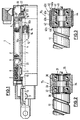
- the linear actuator 1 shown in the drawing it is a permanently excited, multi-phase and multi-pole servo motor.
- a motor housing 2 of the actuator 1 is not closer to one via a motor mounting 3 shown device, for example.
- a welding gun attached and receives a rotatably mounted hollow shaft rotor 4.
- Bearing of the hollow shaft rotor 4 is a floating radial bearing 5 and a bearing combination of axial and radial bearings 6 provided.
- On the outside of the hollow shaft rotor 3 is a plurality of over the circumference of the hollow shaft rotor 4th Distributed magnets 7 arranged with a magnetic field in Interaction that is generated by a stator 8, of the stator space provided around the hollow shaft rotor 4 9 is attached.
- a spindle nut 10 With the hollow shaft rotor 4 is a spindle nut 10 via a Key 11 or the like. Non-rotatably connected. Through the spindle nut 10 is a spindle designed as a ball screw 12 performed, which protrude from the motor housing 2 End 13 via a torque arm, not shown is secured against twisting. This can be done, for example Connect the spindle 12 with a robot welding gun respectively.
- a pin 14 is provided at the other end of the spindle, which carries a support bearing 15 described below.
- the Pin 14 can be integrally formed with the spindle 12 or be screwed tight.
- the interior 16 of the hollow shaft rotor accommodating the spindle 12 4 is through the support bearing 15 into a first chamber 16a and a second chamber 16b divided and on the support bearing 15 facing away from the end of the first chamber 16a by a Cap 17 closed, which is screwed to the hollow shaft rotor 4 is.
- First passages 18 are formed in the cap 17, via which the first chamber 16a of the hollow shaft rotor 4 with one in the Motor housing 2 trained resolver 19 in connection stands.
- the resolver space 19 is connected via second passages 20 connected to the stator chamber 9, which in turn via third Passages 21 with the second chamber 16b of the hollow shaft rotor 4 communicates. This will equalize the pressure between the first and second chambers 16a, b of the hollow shaft rotor 4 allows.
- the resolver space 19 there is a transmitter system on the motor housing 2 (Resolver) for recording the speed and position the hollow shaft rotor 4 arranged.
- the resolver 22 detects the rotor part 23 attached to the cap 17 Rotation speed of the hollow shaft rotor 4 and can thereby the speed and position of the spindle 12 or one at the front end of the tool attached, for example Robot welding gun, determine and connect to a programmable Forward control, based on that of the Linear actuator 1 drives the device.
- the support bearing 15 1 has a slide bearing sleeve 30 made of, for example, metal mixed with graphite.
- the slide bearing sleeve 30 In the slide bearing sleeve 30, two radial bearings 31, 32 designed as ball bearings are inserted, which bear against a shoulder 33 of the slide bearing sleeve 30 and are additionally held tension-free via a spacer ring 34.
- the support bearing 15 1 is clamped on the pin 14 of the spindle 12 with the aid of mounting disks 35, 36.
- a slide bearing sleeve 40 designed as a two-part ring 40a, 40b is provided, onto which a conventional slide bearing 40c is pushed.
- Two radial bearings 41, 42 designed as ball bearings are inserted into the slide bearing sleeve and rest on shoulders 43a, b of the rings 40a, b.
- the radial bearings 41, 42 are also held free of tension by means of a spacer ring 44 and clamped onto the pin 14 of the spindle 12 with the aid of mounting disks 45, 46.
- the linear actuator 1 is designed essentially as described above with a support bearing 15 1 or 15 2 . Since the effect of the support bearing variants 15 1 and 15 2 is essentially the same, a description of the functioning of the linear actuator 1 is given below for both variants.
- the permanent-magnet, in particular 3-phase and 6-pole servo motor drives the hollow shaft rotor 4 with the aid of the magnetic field generated by the stator 8, so that the rotor 4 rotates.
- the spindle nut 10 which is connected in a rotationally fixed manner to the rotor 4, also rotates and moves the spindle 12 out of the hollow shaft rotor 4 or into it, depending on the direction of rotation of the motor.
- the axial forces generated by the translational movement of the spindle 12 are absorbed by the slide bearing 30, 40 of the support bearing 15 1 or 15 2 , while the radial forces generated by the rotation of the hollow shaft rotor 4 by the radial bearings 31, 32 or 41, 42 of Support bearing 15 1 and 15 2 are added. Since the support bearing 15 absorbs the axial and radial forces, the thread of the spindle 12 is essentially not loaded, so that its service life is significantly increased.
- Cap 17 The rotary motion of those connected to the hollow shaft rotor 4 Cap 17 is captured via the encoder system 22 and from this the The speed and position of the hollow shaft rotor 4 are determined. There through the cap 17 a the rotor of a standard motor appropriate rotor design can be achieved cost-effective feedback system 22 used become.
Landscapes
- Engineering & Computer Science (AREA)
- Mechanical Engineering (AREA)
- General Engineering & Computer Science (AREA)
- Power Engineering (AREA)
- Robotics (AREA)
- Connection Of Motors, Electrical Generators, Mechanical Devices, And The Like (AREA)
- Transmission Devices (AREA)
Abstract
Description
- Fig. 1
- einen schematischen Teilschnitt durch ein erfindungsgemäßes Linearstellglied,
- Fig. 2
- eine vergrößerte Darstellung des Stützlagers gemäß einer ersten Ausführungsform und
- Fig. 3
- eine vergrößerte Darstellung des Stützlagers gemäß einer zweiten Ausführungsform der Erfindung.
- 1
- Linearstellglied
- 2
- Motorgehäuse
- 3
- Motoraufhängung
- 4
- Hohlwellenrotor
- 5
- Radiallager
- 6
- Lagerkombination
- 7
- Magnet
- 8
- Stator
- 9
- Statorraum
- 10
- Spindelmutter
- 11
- Passfeder
- 12
- Spindel
- 13
- vorderes Ende der Spindel
- 14
- Zapfen
- 15
- Stützlager
- 16
- Innenraum
- 16a
- erste Kammer
- 16b
- zweite Kammer
- 17
- Kappe
- 18
- erster Durchgang
- 19
- Resolverraum
- 20
- zweiter Durchgang
- 21
- dritter Durchgang
- 22
- Gebersystem, Resolver
- 23
- Stift
- 30
- Gleitlagerhülse
- 31
- Radiallager
- 32
- Radiallager
- 33
- Absatz
- 34
- Distanzring
- 35
- Montagescheibe
- 36
- Montagescheibe
- 40
- Gleitlagerhülse
- 40a, b
- Ring
- 40c
- Gleitlager
- 41
- Radiallager
- 42
- Radiallager
- 43a, b
- Absatz
- 44
- Distanzring
- 45
- Montagescheibe
- 46
- Montagescheibe
Claims (11)
- Linearstellglied für die Umsetzung einer rotatorischen Antriebskraft in eine translatorische Stellbewegung mit:einem Gehäuse (2),einem in dem Gehäuse (2) drehbar gelagerten, bspw. permanenterregten Hohlwellenrotor (4), der über einen mehrphasigen Stator (8) oder dgl. drehangetrieben wird, undeiner in dem Hohlwellenrotor (4) längsverschieblich angeordneten Spindel (12), die mit einer mit dem Hohlwellenrotor (4) verbundenen Spindelmutter (10) in Gewindeeingriff steht und gegen eine Drehung abgestützt ist,
dadurch gekennzeichnet, dass die Spindel (12) in dem Hohlwellenrotor (4) über ein gleitendes Stützlager (15) gelagert ist, das auf der Spindel (12) angebracht ist und sich mit dieser innerhalb des Hohlwellenrotors (4) verschiebt. - Linearstellglied nach Anspruch 1, dadurch gekennzeichnet, dass vorzugsweise an dem der Spindelmutter (10) abgewandten Ende der Spindel (12) ein Zapfen (14) vorgesehen ist, auf dem das Stützlager (15) angebracht ist.
- Linearstellglied nach Anspruch 1 oder 2, dadurch gekennzeichnet, dass das Stützlager (15) eine Gleitlagerhülse (30, 40) aufweist, in welche ein oder mehrere Radiallager (31, 32; 41, 42) eingebracht sind.
- Linearstellglied nach Anspruch 3, dadurch gekennzeichnet, dass die Gleitlagerhülse (30) eine vorzugsweise mit Graphit oder dgl. versetzte Metallhülse ist.
- Linearstellglied nach Anspruch 3, dadurch gekennzeichnet, dass die Gleitlagerhülse (40) einen vorzugsweise zweiteiligen Ring (40a, 40b) aufweist, auf den ein Gleitlager (40c) aufgeschoben ist.
- Linearstellglied nach einem der Ansprüche 3 bis 5, dadurch gekennzeichnet, dass zwischen den Radiallagern (31, 32; 41, 42) ein Distanzring (34; 44) oder dgl. vorgesehen ist.
- Linearstellglied nach einem der vorhergehenden Ansprüche, dadurch gekennzeichnet, dass das Stützlager (15) über Montagescheiben (34, 36; 44, 46) oder dgl. fest auf der Spindel (12) verklemmt wird.
- Linearstellglied nach einem der vorhergehenden Ansprüche, dadurch gekennzeichnet, dass der Hohlwellenrotor (4) an seinem dem Stützlager (15) der Spindel (12) zugewandten Ende über eine Kappe (17) oder dgl. verschlossen ist.
- Linearstellglied nach Anspruch 8, dadurch gekennzeichnet, dass der Kappe (17) oder dgl. ein Gebersystem (22) zur Erfassung der Geschwindigkeit und Lage des Hohlwellenrotors (4) zugeordnet ist.
- Linearstellglied nach einem der vorhergehenden Ansprüche, dadurch gekennzeichnet, dass der die Spindel (12) aufnehmende Innenraum (16) des Hohlwellenrotors (4) durch das Stützlager (15) in einer erste und eine zweite Kammer (16a, b) unterteilt wird und dass die erste und die zweite Kammer (16a, b) über Durchgänge (18, 20, 21) miteinander in Verbindung stehen.
- Linearstellglied nach Anspruch 10, dadurch gekennzeichnet, dass in der Kappe (17) ein erster Durchgang (18) ausgebildet ist, über den die erste Kammer (16a) des Hohlwellenrotors (4) mit einem das Gebersystem (22) aufnehmenden Resolverraum (19) verbunden ist, dass der Resolverraum (19) über einen zweiten Durchgang (20) mit einem den Stator (8) oder dgl. aufnehmenden Statorraum (9) verbunden ist und dass der Statorraum (9) über einen dritten Durchgang (21) mit der zweiten Kammer (16b) des Hohlwellenrotors (4) in Verbindung steht.
Priority Applications (1)
| Application Number | Priority Date | Filing Date | Title |
|---|---|---|---|
| DE20022449U DE20022449U1 (de) | 1999-09-30 | 2000-08-25 | Linearstellglied |
Applications Claiming Priority (4)
| Application Number | Priority Date | Filing Date | Title |
|---|---|---|---|
| DE29917213U DE29917213U1 (de) | 1999-09-30 | 1999-09-30 | Roboterschweißzange |
| DE29917213U | 1999-09-30 | ||
| DE19948265A DE19948265C2 (de) | 1999-09-30 | 1999-10-06 | Linearstellglied |
| DE19948265 | 1999-10-06 |
Publications (2)
| Publication Number | Publication Date |
|---|---|
| EP1089019A1 true EP1089019A1 (de) | 2001-04-04 |
| EP1089019B1 EP1089019B1 (de) | 2004-03-31 |
Family
ID=26055205
Family Applications (1)
| Application Number | Title | Priority Date | Filing Date |
|---|---|---|---|
| EP00118491A Expired - Lifetime EP1089019B1 (de) | 1999-09-30 | 2000-08-25 | Linearstellglied |
Country Status (2)
| Country | Link |
|---|---|
| EP (1) | EP1089019B1 (de) |
| AT (1) | ATE263323T1 (de) |
Cited By (7)
| Publication number | Priority date | Publication date | Assignee | Title |
|---|---|---|---|---|
| WO2002021019A1 (de) * | 2000-09-09 | 2002-03-14 | Ina-Schaeffler Kg | Vorschubeinheit |
| EP1338829A1 (de) | 2002-02-26 | 2003-08-27 | Baumüller Nürnberg Gmbh | Umsetzanordnung mit Spindeltrieb |
| WO2003066269A3 (de) * | 2002-02-05 | 2003-12-11 | Swac Electronic Gmbh | Antriebsvorrichtung für eine schweisszange |
| EP1600665A1 (de) * | 2004-05-24 | 2005-11-30 | Hans-Peter Canonica | Elektromotorischer Verstellantrieb |
| WO2009146737A1 (en) * | 2008-06-03 | 2009-12-10 | Ab Skf | Linear actuator |
| WO2014173667A1 (fr) * | 2013-04-24 | 2014-10-30 | Sonceboz Sa | Actionneur electrique a tige filetee |
| WO2017077042A1 (de) * | 2015-11-04 | 2017-05-11 | Elektrosil Systeme Der Elektronik Gmbh | Verstellvorrichtung zur verstellung einer kopfstützenposition mit direktantrieb |
Families Citing this family (2)
| Publication number | Priority date | Publication date | Assignee | Title |
|---|---|---|---|---|
| DE102006014834A1 (de) * | 2006-03-30 | 2007-10-04 | Otto Bihler Handels-Beteiligungs-Gmbh | Werkzeugtreiberaggregat |
| DE102006043611A1 (de) * | 2006-09-16 | 2008-03-27 | Ina - Drives & Mechatronics Gmbh & Co. Ohg | Antriebseinheit |
Citations (6)
| Publication number | Priority date | Publication date | Assignee | Title |
|---|---|---|---|---|
| US2654848A (en) * | 1949-12-08 | 1953-10-06 | Schaefer Edward John | Submergible motor construction |
| DE2809954A1 (de) * | 1977-03-11 | 1978-09-14 | Peder Ulrik Poulsen | Getriebe zum umwandeln einer drehenden in eine hin- und hergehende bewegung und umgekehrt |
| US4463291A (en) * | 1979-12-31 | 1984-07-31 | Andale Company | Automatic control system and valve actuator |
| JPS6155461A (ja) * | 1984-08-27 | 1986-03-19 | Masanobu Fukuzumi | 直動形駆動装置 |
| FR2580362A1 (fr) * | 1985-04-10 | 1986-10-17 | Bertin & Cie | Dispositif reversible de transformation d'un mouvement rotatif en un mouvement rectiligne alternatif |
| JPH11299169A (ja) * | 1998-04-10 | 1999-10-29 | Yaskawa Electric Corp | リニアアクチュエータ |
-
2000
- 2000-08-25 EP EP00118491A patent/EP1089019B1/de not_active Expired - Lifetime
- 2000-08-25 AT AT00118491T patent/ATE263323T1/de active
Patent Citations (6)
| Publication number | Priority date | Publication date | Assignee | Title |
|---|---|---|---|---|
| US2654848A (en) * | 1949-12-08 | 1953-10-06 | Schaefer Edward John | Submergible motor construction |
| DE2809954A1 (de) * | 1977-03-11 | 1978-09-14 | Peder Ulrik Poulsen | Getriebe zum umwandeln einer drehenden in eine hin- und hergehende bewegung und umgekehrt |
| US4463291A (en) * | 1979-12-31 | 1984-07-31 | Andale Company | Automatic control system and valve actuator |
| JPS6155461A (ja) * | 1984-08-27 | 1986-03-19 | Masanobu Fukuzumi | 直動形駆動装置 |
| FR2580362A1 (fr) * | 1985-04-10 | 1986-10-17 | Bertin & Cie | Dispositif reversible de transformation d'un mouvement rotatif en un mouvement rectiligne alternatif |
| JPH11299169A (ja) * | 1998-04-10 | 1999-10-29 | Yaskawa Electric Corp | リニアアクチュエータ |
Non-Patent Citations (2)
| Title |
|---|
| PATENT ABSTRACTS OF JAPAN vol. 010, no. 218 (M - 503) 30 July 1986 (1986-07-30) * |
| PATENT ABSTRACTS OF JAPAN vol. 2000, no. 01 31 January 2000 (2000-01-31) * |
Cited By (10)
| Publication number | Priority date | Publication date | Assignee | Title |
|---|---|---|---|---|
| WO2002021019A1 (de) * | 2000-09-09 | 2002-03-14 | Ina-Schaeffler Kg | Vorschubeinheit |
| WO2003066269A3 (de) * | 2002-02-05 | 2003-12-11 | Swac Electronic Gmbh | Antriebsvorrichtung für eine schweisszange |
| US7435924B2 (en) | 2002-02-05 | 2008-10-14 | Swac Electronic Gmbh | Drive device for welding tongs |
| EP1338829A1 (de) | 2002-02-26 | 2003-08-27 | Baumüller Nürnberg Gmbh | Umsetzanordnung mit Spindeltrieb |
| EP1600665A1 (de) * | 2004-05-24 | 2005-11-30 | Hans-Peter Canonica | Elektromotorischer Verstellantrieb |
| WO2009146737A1 (en) * | 2008-06-03 | 2009-12-10 | Ab Skf | Linear actuator |
| WO2014173667A1 (fr) * | 2013-04-24 | 2014-10-30 | Sonceboz Sa | Actionneur electrique a tige filetee |
| US10502293B2 (en) | 2013-04-24 | 2019-12-10 | Sonceboz Sa | Electric actuator with threaded rod |
| WO2017077042A1 (de) * | 2015-11-04 | 2017-05-11 | Elektrosil Systeme Der Elektronik Gmbh | Verstellvorrichtung zur verstellung einer kopfstützenposition mit direktantrieb |
| CN108602459A (zh) * | 2015-11-04 | 2018-09-28 | 电子系统股份有限公司 | 利用直接驱动装置调节头枕位置的调节设备 |
Also Published As
| Publication number | Publication date |
|---|---|
| EP1089019B1 (de) | 2004-03-31 |
| ATE263323T1 (de) | 2004-04-15 |
Similar Documents
| Publication | Publication Date | Title |
|---|---|---|
| DE3416938C2 (de) | Von einem Elektromotor angetriebenes, eine Längsbewegung ausführendes Stellglied | |
| EP1342018B1 (de) | Betätigungseinheit für eine elektromechanisch betätigbare scheibenbremse | |
| DE3808989C2 (de) | ||
| DE69416968T2 (de) | Servolenkung | |
| EP3911475B1 (de) | Spannvorrichtung | |
| EP3464947B1 (de) | Stelleinrichtung und verwendung der stelleinrichtung | |
| EP0743470A1 (de) | Bremsaktor für elektrisch betätigbare Fahrzeugbremse | |
| DE10217123A1 (de) | Spielfreies Lenkgetriebe | |
| DE19948265C2 (de) | Linearstellglied | |
| DE102019112021A1 (de) | Hub-Dreh-Modul | |
| DE102008018610A1 (de) | Stabilisatoranordnung | |
| DE102016124117A1 (de) | Türkomponente mit einem steuerbaren Drehdämpfer | |
| DE69819826T2 (de) | Servosteuersystem | |
| EP1089019B1 (de) | Linearstellglied | |
| EP1511952A1 (de) | Standardantrieb, baureihe mit zwischenflansch | |
| DE112016003059B4 (de) | Gewindetrieb | |
| EP0636819A1 (de) | Schaltvorrichtung für mehrstufige Schaltgetriebe | |
| EP3807556A1 (de) | Spindel für einen aktuator einer steer-by-wire-lenkung sowie steer-by-wire-lenkung | |
| DE102013107378A1 (de) | Antriebsvorrichtung | |
| DE102004056209A1 (de) | Linear verschiebbarer Rotationsantrieb für eine Kunststoffspritzmaschine | |
| DE102007038264B4 (de) | Aktiver Stabilisator zur Wankstabilisierung | |
| DE20022449U1 (de) | Linearstellglied | |
| DE102018205781B4 (de) | Antriebseinrichtung | |
| EP1180843A1 (de) | Linearstellglied | |
| EP0875982A1 (de) | Elektromagnetischer Linearantrieb |
Legal Events
| Date | Code | Title | Description |
|---|---|---|---|
| PUAI | Public reference made under article 153(3) epc to a published international application that has entered the european phase |
Free format text: ORIGINAL CODE: 0009012 |
|
| AK | Designated contracting states |
Kind code of ref document: A1 Designated state(s): AT BE CH CY DE DK ES FI FR GB GR IE IT LI LU MC NL PT SE |
|
| AX | Request for extension of the european patent |
Free format text: AL;LT;LV;MK;RO;SI |
|
| 17P | Request for examination filed |
Effective date: 20010911 |
|
| AKX | Designation fees paid |
Free format text: AT BE CH CY DE DK ES FI FR GB GR IE IT LI LU MC NL PT SE |
|
| 17Q | First examination report despatched |
Effective date: 20021112 |
|
| GRAP | Despatch of communication of intention to grant a patent |
Free format text: ORIGINAL CODE: EPIDOSNIGR1 |
|
| GRAS | Grant fee paid |
Free format text: ORIGINAL CODE: EPIDOSNIGR3 |
|
| GRAA | (expected) grant |
Free format text: ORIGINAL CODE: 0009210 |
|
| RAP1 | Party data changed (applicant data changed or rights of an application transferred) |
Owner name: DANAHER MOTION GMBH |
|
| AK | Designated contracting states |
Kind code of ref document: B1 Designated state(s): AT BE CH CY DE DK ES FI FR GB GR IE IT LI LU MC NL PT SE |
|
| PG25 | Lapsed in a contracting state [announced via postgrant information from national office to epo] |
Ref country code: CY Free format text: LAPSE BECAUSE OF FAILURE TO SUBMIT A TRANSLATION OF THE DESCRIPTION OR TO PAY THE FEE WITHIN THE PRESCRIBED TIME-LIMIT Effective date: 20040331 Ref country code: IE Free format text: LAPSE BECAUSE OF FAILURE TO SUBMIT A TRANSLATION OF THE DESCRIPTION OR TO PAY THE FEE WITHIN THE PRESCRIBED TIME-LIMIT Effective date: 20040331 Ref country code: GB Free format text: LAPSE BECAUSE OF FAILURE TO SUBMIT A TRANSLATION OF THE DESCRIPTION OR TO PAY THE FEE WITHIN THE PRESCRIBED TIME-LIMIT Effective date: 20040331 Ref country code: FI Free format text: LAPSE BECAUSE OF FAILURE TO SUBMIT A TRANSLATION OF THE DESCRIPTION OR TO PAY THE FEE WITHIN THE PRESCRIBED TIME-LIMIT Effective date: 20040331 |
|
| REG | Reference to a national code |
Ref country code: CH Ref legal event code: EP Ref country code: GB Ref legal event code: FG4D Free format text: NOT ENGLISH |
|
| REG | Reference to a national code |
Ref country code: IE Ref legal event code: FG4D Free format text: GERMAN |
|
| REF | Corresponds to: |
Ref document number: 50005873 Country of ref document: DE Date of ref document: 20040506 Kind code of ref document: P |
|
| PG25 | Lapsed in a contracting state [announced via postgrant information from national office to epo] |
Ref country code: SE Free format text: LAPSE BECAUSE OF FAILURE TO SUBMIT A TRANSLATION OF THE DESCRIPTION OR TO PAY THE FEE WITHIN THE PRESCRIBED TIME-LIMIT Effective date: 20040630 Ref country code: DK Free format text: LAPSE BECAUSE OF FAILURE TO SUBMIT A TRANSLATION OF THE DESCRIPTION OR TO PAY THE FEE WITHIN THE PRESCRIBED TIME-LIMIT Effective date: 20040630 Ref country code: GR Free format text: LAPSE BECAUSE OF FAILURE TO SUBMIT A TRANSLATION OF THE DESCRIPTION OR TO PAY THE FEE WITHIN THE PRESCRIBED TIME-LIMIT Effective date: 20040630 |
|
| PG25 | Lapsed in a contracting state [announced via postgrant information from national office to epo] |
Ref country code: ES Free format text: LAPSE BECAUSE OF FAILURE TO SUBMIT A TRANSLATION OF THE DESCRIPTION OR TO PAY THE FEE WITHIN THE PRESCRIBED TIME-LIMIT Effective date: 20040712 |
|
| REG | Reference to a national code |
Ref country code: CH Ref legal event code: NV Representative=s name: OK PAT AG PATENTE MARKEN LIZENZEN |
|
| PG25 | Lapsed in a contracting state [announced via postgrant information from national office to epo] |
Ref country code: LU Free format text: LAPSE BECAUSE OF NON-PAYMENT OF DUE FEES Effective date: 20040825 |
|
| PG25 | Lapsed in a contracting state [announced via postgrant information from national office to epo] |
Ref country code: MC Free format text: LAPSE BECAUSE OF NON-PAYMENT OF DUE FEES Effective date: 20040831 Ref country code: BE Free format text: LAPSE BECAUSE OF NON-PAYMENT OF DUE FEES Effective date: 20040831 |
|
| GBV | Gb: ep patent (uk) treated as always having been void in accordance with gb section 77(7)/1977 [no translation filed] |
Effective date: 20040331 |
|
| REG | Reference to a national code |
Ref country code: IE Ref legal event code: FD4D |
|
| ET | Fr: translation filed | ||
| PLBE | No opposition filed within time limit |
Free format text: ORIGINAL CODE: 0009261 |
|
| STAA | Information on the status of an ep patent application or granted ep patent |
Free format text: STATUS: NO OPPOSITION FILED WITHIN TIME LIMIT |
|
| BERE | Be: lapsed |
Owner name: *DANAHER MOTION G.M.B.H. Effective date: 20040831 |
|
| 26N | No opposition filed |
Effective date: 20050104 |
|
| BERE | Be: lapsed |
Owner name: *DANAHER MOTION G.M.B.H. Effective date: 20040831 |
|
| PG25 | Lapsed in a contracting state [announced via postgrant information from national office to epo] |
Ref country code: PT Free format text: LAPSE BECAUSE OF NON-PAYMENT OF DUE FEES Effective date: 20040831 |
|
| REG | Reference to a national code |
Ref country code: DE Ref legal event code: R081 Ref document number: 50005873 Country of ref document: DE Owner name: KOLLMORGEN EUROPE GMBH, DE Free format text: FORMER OWNER: DANAHER MOTION GMBH, 40489 DUESSELDORF, DE Effective date: 20111229 Ref country code: DE Ref legal event code: R082 Ref document number: 50005873 Country of ref document: DE Representative=s name: KEIL & SCHAAFHAUSEN PATENT- UND RECHTSANWAELTE, DE Effective date: 20111229 |
|
| REG | Reference to a national code |
Ref country code: NL Ref legal event code: TD Effective date: 20120308 |
|
| REG | Reference to a national code |
Ref country code: CH Ref legal event code: PFA Owner name: KOLLMORGEN EUROPE GMBH Free format text: DANAHER MOTION GMBH#WACHHOLDERSTRASSE 40-42#40489 DUESSELDORF (DE) -TRANSFER TO- KOLLMORGEN EUROPE GMBH#PEMPELFURTSTRASSE 1#40880 RATINGEN (DE) |
|
| PGFP | Annual fee paid to national office [announced via postgrant information from national office to epo] |
Ref country code: CH Payment date: 20120221 Year of fee payment: 12 |
|
| REG | Reference to a national code |
Ref country code: FR Ref legal event code: CA Effective date: 20120403 Ref country code: FR Ref legal event code: CD Owner name: KOLLMORGEN EUROPE GMBH, DE Effective date: 20120403 |
|
| REG | Reference to a national code |
Ref country code: AT Ref legal event code: HC Ref document number: 263323 Country of ref document: AT Kind code of ref document: T Owner name: KOLLMORGEN EUROPE GMBH, DE Effective date: 20120807 |
|
| PGFP | Annual fee paid to national office [announced via postgrant information from national office to epo] |
Ref country code: FR Payment date: 20120831 Year of fee payment: 13 |
|
| PGFP | Annual fee paid to national office [announced via postgrant information from national office to epo] |
Ref country code: NL Payment date: 20120824 Year of fee payment: 13 Ref country code: DE Payment date: 20121024 Year of fee payment: 13 |
|
| PGFP | Annual fee paid to national office [announced via postgrant information from national office to epo] |
Ref country code: AT Payment date: 20120822 Year of fee payment: 13 |
|
| REG | Reference to a national code |
Ref country code: NL Ref legal event code: V1 Effective date: 20140301 |
|
| REG | Reference to a national code |
Ref country code: CH Ref legal event code: PL |
|
| REG | Reference to a national code |
Ref country code: AT Ref legal event code: MM01 Ref document number: 263323 Country of ref document: AT Kind code of ref document: T Effective date: 20130825 |
|
| PG25 | Lapsed in a contracting state [announced via postgrant information from national office to epo] |
Ref country code: NL Free format text: LAPSE BECAUSE OF NON-PAYMENT OF DUE FEES Effective date: 20140301 Ref country code: DE Free format text: LAPSE BECAUSE OF NON-PAYMENT OF DUE FEES Effective date: 20140301 Ref country code: CH Free format text: LAPSE BECAUSE OF NON-PAYMENT OF DUE FEES Effective date: 20130831 Ref country code: LI Free format text: LAPSE BECAUSE OF NON-PAYMENT OF DUE FEES Effective date: 20130831 |
|
| REG | Reference to a national code |
Ref country code: DE Ref legal event code: R119 Ref document number: 50005873 Country of ref document: DE Effective date: 20140301 |
|
| REG | Reference to a national code |
Ref country code: FR Ref legal event code: ST Effective date: 20140430 |
|
| PG25 | Lapsed in a contracting state [announced via postgrant information from national office to epo] |
Ref country code: AT Free format text: LAPSE BECAUSE OF NON-PAYMENT OF DUE FEES Effective date: 20130825 |
|
| PG25 | Lapsed in a contracting state [announced via postgrant information from national office to epo] |
Ref country code: FR Free format text: LAPSE BECAUSE OF NON-PAYMENT OF DUE FEES Effective date: 20130902 |
|
| PGFP | Annual fee paid to national office [announced via postgrant information from national office to epo] |
Ref country code: IT Payment date: 20140827 Year of fee payment: 15 |
|
| PG25 | Lapsed in a contracting state [announced via postgrant information from national office to epo] |
Ref country code: IT Free format text: LAPSE BECAUSE OF NON-PAYMENT OF DUE FEES Effective date: 20150825 |