EP1090867A2 - Method and device for placing inserts in folded paper jackets - Google Patents
Method and device for placing inserts in folded paper jackets Download PDFInfo
- Publication number
- EP1090867A2 EP1090867A2 EP00610103A EP00610103A EP1090867A2 EP 1090867 A2 EP1090867 A2 EP 1090867A2 EP 00610103 A EP00610103 A EP 00610103A EP 00610103 A EP00610103 A EP 00610103A EP 1090867 A2 EP1090867 A2 EP 1090867A2
- Authority
- EP
- European Patent Office
- Prior art keywords
- printed
- folded
- edge
- hook
- Prior art date
- Legal status (The legal status is an assumption and is not a legal conclusion. Google has not performed a legal analysis and makes no representation as to the accuracy of the status listed.)
- Granted
Links
Images

Classifications
-
- B—PERFORMING OPERATIONS; TRANSPORTING
- B65—CONVEYING; PACKING; STORING; HANDLING THIN OR FILAMENTARY MATERIAL
- B65H—HANDLING THIN OR FILAMENTARY MATERIAL, e.g. SHEETS, WEBS, CABLES
- B65H39/00—Associating, collating, or gathering articles or webs
- B65H39/02—Associating,collating or gathering articles from several sources
- B65H39/06—Associating,collating or gathering articles from several sources from delivery streams
- B65H39/065—Associating,collating or gathering articles from several sources from delivery streams by collecting in rotary carriers
-
- B—PERFORMING OPERATIONS; TRANSPORTING
- B65—CONVEYING; PACKING; STORING; HANDLING THIN OR FILAMENTARY MATERIAL
- B65H—HANDLING THIN OR FILAMENTARY MATERIAL, e.g. SHEETS, WEBS, CABLES
- B65H2301/00—Handling processes for sheets or webs
- B65H2301/40—Type of handling process
- B65H2301/43—Gathering; Associating; Assembling
- B65H2301/431—Features with regard to the collection, nature, sequence and/or the making thereof
- B65H2301/4317—Signatures, i.e. involving folded main product or jacket
- B65H2301/43171—Inserting subproducts in a signature as main product
- B65H2301/431711—Inserting subproducts in a signature as main product the subproduct being inserted in a direction substantially perpendicular to the fold of the main product
- B65H2301/431716—Inserting subproducts in a signature as main product the subproduct being inserted in a direction substantially perpendicular to the fold of the main product the main product being oriented with opening face upwards
-
- B—PERFORMING OPERATIONS; TRANSPORTING
- B65—CONVEYING; PACKING; STORING; HANDLING THIN OR FILAMENTARY MATERIAL
- B65H—HANDLING THIN OR FILAMENTARY MATERIAL, e.g. SHEETS, WEBS, CABLES
- B65H2301/00—Handling processes for sheets or webs
- B65H2301/40—Type of handling process
- B65H2301/45—Folding, unfolding
- B65H2301/453—Folding, unfolding opening folded material
-
- B—PERFORMING OPERATIONS; TRANSPORTING
- B65—CONVEYING; PACKING; STORING; HANDLING THIN OR FILAMENTARY MATERIAL
- B65H—HANDLING THIN OR FILAMENTARY MATERIAL, e.g. SHEETS, WEBS, CABLES
- B65H2404/00—Parts for transporting or guiding the handled material
- B65H2404/60—Other elements in face contact with handled material
- B65H2404/65—Other elements in face contact with handled material rotating around an axis parallel to face of material and perpendicular to transport direction, e.g. star wheel
- B65H2404/656—Means for disengaging material from element
Definitions
- the present invention concerns a machine for the placing of so-called inserts in folded printed matter, namely newspapers which are supplied in a tight flow with the fold edge foremost, typically from a rotary press with a capacity of 20-25,000 items per hour, and of the kind which comprises a rotating roller with extending, star-shaped support arms which demarcate V-shaped pockets for successive receipt of the arriving printed matter by the accommodation of these with the fold edge in towards the bottom of the V-pockets, and opening elements which during the rotation of the roller effect a slight opening of the folded printed matter in each of the pockets, and in such a manner that during the movement of the pockets past an insertion station, the thus opened printed items can receive a supplied insert, after which the now supplemented printed items are fed further by the rotation of the roller to or past en extraction station where the finished printed matter is extracted from the pockets for further transport, e.g. to a stacking station.
- the one side edge of the folded items consists of a folded-together or glued-together spine of the printed matter product, i.e. at this side it is possible to handle the folded item as if it were an assembled sheet item, including at the said suction outwards, but this will not apply at the opposite side, where the sheets of the printed matter are quite loose in relation to one another.
- a corresponding arrangement is known from DE-A-32 00 594, whereby work is effected with the distinct improvement that newspaper items are folded together around a transverse line lying slightly displaced from the centre cross line of the folded-out newspaper, so that opposite the fold line the folded newspaper will appear with two unequally long, outwardly-extending rectangular edges of the respective half-parts of the folded newspaper.
- This provides the possibility that use can be made of edge gripping means for secure gripping of the free edge of the one folded half part, while relying on the fact that by means of gravitation the other half part can bring about the necessary opening of the folded item to enable an insert to be introduced into the opening. At high working speeds, however, this gravitational effect will not only be too slow but also be of uncertain influence on the folded item, i.e. this method is not suitable for use at the higher speeds of operation.
- the gripping reliability is of decisive importance, and with the present invention it is endeavoured to provide a combination of high gripping security and minimised demands regarding the over-height of the protruding free edge.
- the holding hooks shall wedge themselves in the space between the two folded half parts during the pressing back of the longest protruding half part, which according to the invention is made possible in that the wing-plate, along a part of its outermost extent, is configured with an outwardly, rearwards-inclined profile which will allow said wedging-in while the clamping-fast of the folded item is otherwise maintained. This clamping-fast during the gripping operation will obviously promote operational reliability.
- a second important and even primary characteristic of the invention is that the gripping means, which are arranged at the outer end of the pivotal wing-plate, are not forcibly moved, but merely consist of projecting, passive, pivotal holding hooks which with an outer, inclined nose part will be forced to swing up over the outer edge of the longest protruding half part of the folded newspaper when this is clamped-in by the tilting forward of the wing-plate.
- the gripping means which are arranged at the outer end of the pivotal wing-plate, are not forcibly moved, but merely consist of projecting, passive, pivotal holding hooks which with an outer, inclined nose part will be forced to swing up over the outer edge of the longest protruding half part of the folded newspaper when this is clamped-in by the tilting forward of the wing-plate.
- the wing-plate can be tipped out for opening of the folded item for receiving the insert.
- the holding hooks can be made to release their grip in the simple manner that with an inclined, rearwards-extending release arm part, they impinge against a release cam on the next following fixed support plate, so that the hook parts are forced to swing out from their engagement with the gripped edge of the item.
- the wing-plate can be swung back to an almost closed position of the pocket, where the item with its associated insert can be extracted by suitable extraction means after the releasing of the controlled grippers for the lowest protruding edge part of the item.
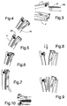
- the machine sketched in fig. 1 works in accordance with well-known principles.
- the main element is a wing wheel 2 which has protruding wing-rods 4 which form V-shaped pockets for receiving folded newspapers 6 delivered in a flow from a rotary press with the fold edge foremost.
- the rotation of the wheel 2 is controlled in such a manner that it can hereby receive a single newspaper in each of the wheel pockets.
- a magazine unit is provided for stacks of inserts 8 in respective magazines 10.
- the inserts can be dropped individually down onto a conveyor belt 12, controlled in such a way that inserts from selected magazines can be successively deposited in insert sets 14.Via a suitable transfer conveyor, these inserts or insert sets can be fed for introduction down into the wheel pockets, in which as shown at 16 the newspapers are held opened for reliable receipt of the inserts in the centre fold.
- the wheel pockets are moved further through an extraction station 18 at which the supplemented newspapers are extracted for feeding further along a conveyor 20 for final stacking or further processing.
- the wing wheel 2 is arranged in the following manner, cf. fig. 2:
- the fixed wings 4 are configured in a tapering manner with a curved front edge forwards in the direction of rotation and with a straight rear edge.
- the hook element is connected to a pinion 26 which co-operates with a rack 28 outermost on a push rod 30, which via a slide guide 32 extends in to a fixed hub part 34 configured with a control cam 36 which, by co-operation with a cam follower 38 on the rod 30, can slide this outwards so that the rack 28 and herewith the hook element 24 is swung downwards to the rear.
- the same wing 4 has a pressure rail 40 lying behind at the rear edge of the wing, pivotally fastened at 42 to the outer end of a support arm 44 which is mounted extending out from a support block 46.
- This support block 46 is pivotally fastened to the hub of the wheel by a bearing 48, and is provided with a cam-follower roller 50 for co-operation with a fixed control cam 52.
- the support arm 44 can hereby be controlled for swinging forwards against the rear edge of the wing 4, where the pressure rail 40 can thus be tilted out around the bearing 42 to assume a position parallel with this rear edge (fig. 4).
- the pressure rail 40 has a rocker arm 54 which is pivotally mounted at 56, and which outermost supports a projecting hook part 58 with a hook 60 extending inwards.
- This arm can be pivoted between the protruding position shown in fig. 2 and the swung rearwards position shown in fig. 3, where the hook 60 is drawn back into abutment against the front side of the outer end of the pressure rail 40.
- This latter position is a normal position, in that the upper end of the rocker arm is spring-loaded in the rearwards direction.
- the outer end part of the pressure rail 40 is characterised in that it is formed with an outwards/rearwards inclined section as shown at 62.
- the support arm 44 is swung forwards (upwards) against its related fixed wing 4 for clamping the closed-together newspaper against this, namely with the view thereafter of being able to open the folded newspaper.
- the newspaper is folded in a slightly asymmetric manner, so that its rearmost half part in the direction of rotation extends slightly to the rear as shown at 66 in fig. 3.
- the support arm 44 and herewith the pressure rail 40 are forced upwards/forwards under rotation of the wheel, whereby the pocket 64 is gradually closed, cf. fig. 4.
- the shortest protruding half-part of the folded newspaper has almost reached forward to the fixed wing 4, while the longer protruding edge part 66 of the other half-part abuts against the front end of the force-controlled hook element. 24.
- the retaining hook 60 on the hook part 58 will be pressed forward over the yielding outer edge of the rearmost, longest protruding edge part 66 of the newspaper item 6, which can be effected partly by a certain bending forward of this edge part, and partly by a certain degree of swinging-out of the hook part 58 brought about by the rearwards-inclined section of the retaining hook 60 itself, cf. fig. 6.
- the pressure rail 40 With a subsequent full clamping of the newspaper item against the fixed wing 4, the pressure rail 40 will be pressed in a parallel manner against the wing for good securing of the newspaper item despite an angled-out position of the support arm 44, with possibility herewith for automatic adjustment to newspaper items of different thickness.
- the pressure pin 55 will be pressed against the fixed wing 4 via the clamped-together newspaper, whereby the rocker arm 54 will swing the retaining hook 58,60 further forward, cf. fig. 7, whereby the hook 60 will grip in over the high edge area 66 of the newspaper with increased security.
- the pressure rail 40 By swinging around the swivel bearing 42, the pressure rail 40, which in the free state is clamped flexibly against the support arm 44, will lie flat in against the newspaper regardless of its thickness.
- both edges of the newspaper will be securely gripped, and the pressure rail 40 can then be controlled for quick re-opening of the pocket 64, fig. 8, in that the retaining hook 58,60 will swing towards the right and thus bring the edge area 66 with it when the pressure pin 55 leaves its firm abutment against the clamped-in newspaper.
- the introduction of the insert 14 can be initiated.
- the pressure rail can again be swung forwards for partial closing of the pocket 64 during the further swinging-down of the wing to the delivery position shown in fig. 10.
- the gripping element 24 on the fixed wing is controlled for opening, after which the newspaper into which the insert has been introduced is ready to be conveyed out by known means.
Landscapes
- Collation Of Sheets And Webs (AREA)
- Feeding Of Articles By Means Other Than Belts Or Rollers (AREA)
- Folding Of Thin Sheet-Like Materials, Special Discharging Devices, And Others (AREA)
- Auxiliary Devices For And Details Of Packaging Control (AREA)
- Toys (AREA)
- Packaging Of Special Articles (AREA)
Abstract
Description
Claims (2)
- Method for the placing of inserts in folded printed matter such as newspapers which are supplied from e.g. a rotary press with high capacity, by which method the printed items are fed in hanging condition with their fold edge lowermost, and are made to fall successively into V-shaped pockets formed by star-shaped support arms extending on a rotating roller, and are subsequently partly unfolded in these pockets for the receipt of the relevant insert(s), after which the printed items are successively conveyed from the pockets, said printed items being folded in such a manner that the fold is displaced from the centreline, so that opposite the fold edge they have a shorter side part and a longer side part extending out to form a protruding edge, which on the individual printed items lies rearmost in the direction in which they are fed, characterised in thatthe printed item which falls down into the pocket is influenced in the forwards direction for clamping abutment against the foremost support arm of the pocket,the hook element (24) is thereafter swung rearwards from the foremost support arm of the pocket, i.e. rearwards for the drawing back of the protruding edge (66) and inwards behind the outer edge area of the shorter side part for the retaming of this side part,a clamping rail (40), pivotally suspended in the pocket and with an outer, projecting gripping hook (60), is thereafter swung forwards to a position in which the gripping hook (60) extends in front of the upstanding edge (66),thereafter, the clamping rail is swung rearwards while bringing with it the longer side part of the printed item, which is now retained by the gripping hook, for the opening of the printed item immediately before the introduction of the insert,thereafter or at the same time herewith, the gripping hook is influenced for the release of the protruding edge,the clamping rail is thereafter swung forwards again for complete or partial folding-together of the printed item, andthe printed item is then conveyed out of the pocket, if necessary after a short swinging back of the pressure rail.
- Machine for the execution of the method according to claim 1, and with the main characteristic as appears from the description and the drawing.
Applications Claiming Priority (2)
| Application Number | Priority Date | Filing Date | Title |
|---|---|---|---|
| DKPA199901449 | 1999-10-08 | ||
| DK144999 | 1999-10-08 |
Publications (3)
| Publication Number | Publication Date |
|---|---|
| EP1090867A2 true EP1090867A2 (en) | 2001-04-11 |
| EP1090867A3 EP1090867A3 (en) | 2002-09-04 |
| EP1090867B1 EP1090867B1 (en) | 2004-09-08 |
Family
ID=8104946
Family Applications (1)
| Application Number | Title | Priority Date | Filing Date |
|---|---|---|---|
| EP00610103A Expired - Lifetime EP1090867B1 (en) | 1999-10-08 | 2000-10-09 | Method and device for placing inserts in folded paper jackets |
Country Status (3)
| Country | Link |
|---|---|
| EP (1) | EP1090867B1 (en) |
| AT (1) | ATE275525T1 (en) |
| DE (1) | DE60013523T2 (en) |
Cited By (2)
| Publication number | Priority date | Publication date | Assignee | Title |
|---|---|---|---|---|
| US8376123B2 (en) | 2010-05-31 | 2013-02-19 | Ferag Ag | Device and method for opening printed products |
| CN111591061A (en) * | 2020-05-14 | 2020-08-28 | 远光软件股份有限公司 | Accounting document prints system of filing |
Families Citing this family (3)
| Publication number | Priority date | Publication date | Assignee | Title |
|---|---|---|---|---|
| CH705359A1 (en) | 2011-08-15 | 2013-02-15 | Ferag Ag | Method and device for collecting flat objects. |
| CH705360A1 (en) | 2011-08-15 | 2013-02-15 | Ferag Ag | Method and device for collecting flat objects. |
| CH706457A1 (en) | 2012-04-30 | 2013-10-31 | Ferag Ag | Method and apparatus for the insertion of objects into folded printed products. |
Family Cites Families (5)
| Publication number | Priority date | Publication date | Assignee | Title |
|---|---|---|---|---|
| US4046367A (en) * | 1975-11-10 | 1977-09-06 | American Newspaper Publishers Association, Incorporated | Modified high speed paper inserting apparatus and method |
| US4373710A (en) * | 1980-08-22 | 1983-02-15 | Nolan Systems, Inc. | Apparatus for inserting supplementary material into newspaper jackets |
| DE3200594A1 (en) * | 1982-01-12 | 1983-07-21 | Reinhard 6300 Gießen Kluge | Device for inserting newspaper supplements into folded newspapers |
| SE464757B (en) * | 1989-10-06 | 1991-06-10 | Wamac Ab | PROCEDURE AND DEVICE FOR PAGE OF ANNEXES IN MAGAZINES |
| US5112036A (en) * | 1990-08-27 | 1992-05-12 | Graphic Management Associates, Inc. | Opener for folder printed products |
-
2000
- 2000-10-09 AT AT00610103T patent/ATE275525T1/en not_active IP Right Cessation
- 2000-10-09 DE DE60013523T patent/DE60013523T2/en not_active Expired - Lifetime
- 2000-10-09 EP EP00610103A patent/EP1090867B1/en not_active Expired - Lifetime
Cited By (3)
| Publication number | Priority date | Publication date | Assignee | Title |
|---|---|---|---|---|
| US8376123B2 (en) | 2010-05-31 | 2013-02-19 | Ferag Ag | Device and method for opening printed products |
| CN111591061A (en) * | 2020-05-14 | 2020-08-28 | 远光软件股份有限公司 | Accounting document prints system of filing |
| CN111591061B (en) * | 2020-05-14 | 2021-07-13 | 远光软件股份有限公司 | Accounting document prints system of filing |
Also Published As
| Publication number | Publication date |
|---|---|
| EP1090867B1 (en) | 2004-09-08 |
| ATE275525T1 (en) | 2004-09-15 |
| DE60013523T2 (en) | 2005-09-15 |
| EP1090867A3 (en) | 2002-09-04 |
| DE60013523D1 (en) | 2004-10-14 |
Similar Documents
| Publication | Publication Date | Title |
|---|---|---|
| US5269504A (en) | Insertion of supplements into newspapers | |
| US8556252B2 (en) | Device and method to supply print products to a processing section | |
| EP1090867B1 (en) | Method and device for placing inserts in folded paper jackets | |
| FI104550B (en) | Inserting attachments in a newspaper | |
| AU667409B2 (en) | Process and apparatus for opening folded printing products | |
| US5354043A (en) | Process and device for opening folded print products | |
| HK1041405A1 (en) | Device and method for preparing a book spine for binding | |
| CA2145372C (en) | Apparatus for feeding sheet-like products to a processing device for printed products | |
| US7192028B2 (en) | Device for processing printed products supplied to a stacking device | |
| US5067700A (en) | Method and apparatus for attaching inserts to moving sheets | |
| EP2325122A1 (en) | Method and device for preparing and feeding digital-printed signatures to a machine | |
| NO179278B (en) | Device for opening and forwarding of printing products | |
| AU711307B2 (en) | Device for feeding printed products to a further processing point | |
| AU2003203510B2 (en) | Method of Conveying Flat, Flexible Products and Apparatus for Implementing the Method | |
| CA2157232C (en) | Conveying device for feeding sheet-like products to a processing machine for printed products | |
| US20060097440A1 (en) | Method and apparatus for placing or inserting printed supplements into printed core products | |
| CA2468357A1 (en) | System, device and method for feeding flat articles | |
| US8800749B2 (en) | Apparatus for processing flat articles, in particular print products | |
| US6769678B2 (en) | Sheet separating device | |
| US5658422A (en) | Device for feeding a machine which processes printed sheets | |
| US6793211B2 (en) | Pocket wheel feeding device | |
| JP4093645B2 (en) | Book or temporary binding book manufacturing method | |
| US8602406B2 (en) | Signature transport device with rotary arm and method |
Legal Events
| Date | Code | Title | Description |
|---|---|---|---|
| PUAI | Public reference made under article 153(3) epc to a published international application that has entered the european phase |
Free format text: ORIGINAL CODE: 0009012 |
|
| AK | Designated contracting states |
Kind code of ref document: A2 Designated state(s): AT BE CH CY DE DK ES FI FR GB GR IE IT LI LU MC NL PT SE |
|
| AX | Request for extension of the european patent |
Free format text: AL;LT;LV;MK;RO;SI |
|
| PUAL | Search report despatched |
Free format text: ORIGINAL CODE: 0009013 |
|
| AK | Designated contracting states |
Kind code of ref document: A3 Designated state(s): AT BE CH CY DE DK ES FI FR GB GR IE IT LI LU MC NL PT SE |
|
| AX | Request for extension of the european patent |
Free format text: AL;LT;LV;MK;RO;SI |
|
| RIC1 | Information provided on ipc code assigned before grant |
Free format text: 7B 65H 39/065 A, 7B 42C 1/10 B, 7B 65H 5/30 B, 7B 42B 9/02 B, 7B 41F 13/68 B |
|
| 17P | Request for examination filed |
Effective date: 20030130 |
|
| AKX | Designation fees paid |
Designated state(s): AT BE CH CY DE DK ES FI FR GB GR IE IT LI LU MC NL PT SE |
|
| AXX | Extension fees paid |
Extension state: SI Payment date: 20030130 Extension state: LV Payment date: 20030130 Extension state: MK Payment date: 20030130 Extension state: AL Payment date: 20030130 Extension state: RO Payment date: 20030130 Extension state: LT Payment date: 20030130 |
|
| 17Q | First examination report despatched |
Effective date: 20030828 |
|
| GRAP | Despatch of communication of intention to grant a patent |
Free format text: ORIGINAL CODE: EPIDOSNIGR1 |
|
| GRAS | Grant fee paid |
Free format text: ORIGINAL CODE: EPIDOSNIGR3 |
|
| GRAA | (expected) grant |
Free format text: ORIGINAL CODE: 0009210 |
|
| AK | Designated contracting states |
Kind code of ref document: B1 Designated state(s): AT BE CH CY DE DK ES FI FR GB GR IE IT LI LU MC NL PT SE |
|
| AX | Request for extension of the european patent |
Extension state: AL LT LV MK RO SI |
|
| PG25 | Lapsed in a contracting state [announced via postgrant information from national office to epo] |
Ref country code: CH Free format text: LAPSE BECAUSE OF FAILURE TO SUBMIT A TRANSLATION OF THE DESCRIPTION OR TO PAY THE FEE WITHIN THE PRESCRIBED TIME-LIMIT Effective date: 20040908 Ref country code: FI Free format text: LAPSE BECAUSE OF FAILURE TO SUBMIT A TRANSLATION OF THE DESCRIPTION OR TO PAY THE FEE WITHIN THE PRESCRIBED TIME-LIMIT Effective date: 20040908 Ref country code: AT Free format text: LAPSE BECAUSE OF FAILURE TO SUBMIT A TRANSLATION OF THE DESCRIPTION OR TO PAY THE FEE WITHIN THE PRESCRIBED TIME-LIMIT Effective date: 20040908 Ref country code: BE Free format text: LAPSE BECAUSE OF FAILURE TO SUBMIT A TRANSLATION OF THE DESCRIPTION OR TO PAY THE FEE WITHIN THE PRESCRIBED TIME-LIMIT Effective date: 20040908 Ref country code: LI Free format text: LAPSE BECAUSE OF FAILURE TO SUBMIT A TRANSLATION OF THE DESCRIPTION OR TO PAY THE FEE WITHIN THE PRESCRIBED TIME-LIMIT Effective date: 20040908 Ref country code: ES Free format text: LAPSE BECAUSE OF FAILURE TO SUBMIT A TRANSLATION OF THE DESCRIPTION OR TO PAY THE FEE WITHIN THE PRESCRIBED TIME-LIMIT Effective date: 20040908 Ref country code: FR Free format text: LAPSE BECAUSE OF NON-PAYMENT OF DUE FEES Effective date: 20040908 Ref country code: CY Free format text: LAPSE BECAUSE OF FAILURE TO SUBMIT A TRANSLATION OF THE DESCRIPTION OR TO PAY THE FEE WITHIN THE PRESCRIBED TIME-LIMIT Effective date: 20040908 Ref country code: NL Free format text: LAPSE BECAUSE OF FAILURE TO SUBMIT A TRANSLATION OF THE DESCRIPTION OR TO PAY THE FEE WITHIN THE PRESCRIBED TIME-LIMIT Effective date: 20040908 |
|
| REG | Reference to a national code |
Ref country code: GB Ref legal event code: FG4D |
|
| REG | Reference to a national code |
Ref country code: CH Ref legal event code: EP |
|
| REG | Reference to a national code |
Ref country code: IE Ref legal event code: FG4D |
|
| PG25 | Lapsed in a contracting state [announced via postgrant information from national office to epo] |
Ref country code: LU Free format text: LAPSE BECAUSE OF NON-PAYMENT OF DUE FEES Effective date: 20041009 |
|
| REF | Corresponds to: |
Ref document number: 60013523 Country of ref document: DE Date of ref document: 20041014 Kind code of ref document: P |
|
| PG25 | Lapsed in a contracting state [announced via postgrant information from national office to epo] |
Ref country code: MC Free format text: LAPSE BECAUSE OF NON-PAYMENT OF DUE FEES Effective date: 20041031 |
|
| PG25 | Lapsed in a contracting state [announced via postgrant information from national office to epo] |
Ref country code: GR Free format text: LAPSE BECAUSE OF FAILURE TO SUBMIT A TRANSLATION OF THE DESCRIPTION OR TO PAY THE FEE WITHIN THE PRESCRIBED TIME-LIMIT Effective date: 20041208 Ref country code: DK Free format text: LAPSE BECAUSE OF FAILURE TO SUBMIT A TRANSLATION OF THE DESCRIPTION OR TO PAY THE FEE WITHIN THE PRESCRIBED TIME-LIMIT Effective date: 20041208 |
|
| REG | Reference to a national code |
Ref country code: SE Ref legal event code: TRGR |
|
| LTIE | Lt: invalidation of european patent or patent extension |
Effective date: 20040908 |
|
| NLV1 | Nl: lapsed or annulled due to failure to fulfill the requirements of art. 29p and 29m of the patents act | ||
| REG | Reference to a national code |
Ref country code: CH Ref legal event code: PL |
|
| PLBE | No opposition filed within time limit |
Free format text: ORIGINAL CODE: 0009261 |
|
| STAA | Information on the status of an ep patent application or granted ep patent |
Free format text: STATUS: NO OPPOSITION FILED WITHIN TIME LIMIT |
|
| 26N | No opposition filed |
Effective date: 20050609 |
|
| EN | Fr: translation not filed | ||
| PG25 | Lapsed in a contracting state [announced via postgrant information from national office to epo] |
Ref country code: PT Free format text: LAPSE BECAUSE OF NON-PAYMENT OF DUE FEES Effective date: 20050208 |
|
| PGFP | Annual fee paid to national office [announced via postgrant information from national office to epo] |
Ref country code: IE Payment date: 20100915 Year of fee payment: 11 |
|
| PGFP | Annual fee paid to national office [announced via postgrant information from national office to epo] |
Ref country code: DE Payment date: 20101020 Year of fee payment: 11 |
|
| PGFP | Annual fee paid to national office [announced via postgrant information from national office to epo] |
Ref country code: IT Payment date: 20101019 Year of fee payment: 11 Ref country code: GB Payment date: 20101019 Year of fee payment: 11 Ref country code: SE Payment date: 20101007 Year of fee payment: 11 |
|
| GBPC | Gb: european patent ceased through non-payment of renewal fee |
Effective date: 20111009 |
|
| REG | Reference to a national code |
Ref country code: SE Ref legal event code: EUG |
|
| PG25 | Lapsed in a contracting state [announced via postgrant information from national office to epo] |
Ref country code: DE Free format text: LAPSE BECAUSE OF NON-PAYMENT OF DUE FEES Effective date: 20120501 |
|
| REG | Reference to a national code |
Ref country code: IE Ref legal event code: MM4A |
|
| REG | Reference to a national code |
Ref country code: DE Ref legal event code: R119 Ref document number: 60013523 Country of ref document: DE Effective date: 20120501 |
|
| PG25 | Lapsed in a contracting state [announced via postgrant information from national office to epo] |
Ref country code: IT Free format text: LAPSE BECAUSE OF NON-PAYMENT OF DUE FEES Effective date: 20111009 Ref country code: GB Free format text: LAPSE BECAUSE OF NON-PAYMENT OF DUE FEES Effective date: 20111009 |
|
| PG25 | Lapsed in a contracting state [announced via postgrant information from national office to epo] |
Ref country code: IE Free format text: LAPSE BECAUSE OF NON-PAYMENT OF DUE FEES Effective date: 20111009 Ref country code: SE Free format text: LAPSE BECAUSE OF NON-PAYMENT OF DUE FEES Effective date: 20111010 |