EP1091166A1 - Light coupling and distribution system - Google Patents
Light coupling and distribution system Download PDFInfo
- Publication number
- EP1091166A1 EP1091166A1 EP00308171A EP00308171A EP1091166A1 EP 1091166 A1 EP1091166 A1 EP 1091166A1 EP 00308171 A EP00308171 A EP 00308171A EP 00308171 A EP00308171 A EP 00308171A EP 1091166 A1 EP1091166 A1 EP 1091166A1
- Authority
- EP
- European Patent Office
- Prior art keywords
- light
- lighting system
- recited
- optical fiber
- coupler
- Prior art date
- Legal status (The legal status is an assumption and is not a legal conclusion. Google has not performed a legal analysis and makes no representation as to the accuracy of the status listed.)
- Granted
Links
- 230000008878 coupling Effects 0.000 title claims abstract description 8
- 238000010168 coupling process Methods 0.000 title claims abstract description 8
- 238000005859 coupling reaction Methods 0.000 title claims abstract description 8
- 239000013307 optical fiber Substances 0.000 claims abstract description 23
- 239000000835 fiber Substances 0.000 claims abstract description 12
- 230000005540 biological transmission Effects 0.000 description 1
- 238000010586 diagram Methods 0.000 description 1
- 238000005286 illumination Methods 0.000 description 1
- 238000005555 metalworking Methods 0.000 description 1
- 230000003287 optical effect Effects 0.000 description 1
- 238000005086 pumping Methods 0.000 description 1
- 238000004513 sizing Methods 0.000 description 1
Images

Classifications
-
- G—PHYSICS
- G02—OPTICS
- G02B—OPTICAL ELEMENTS, SYSTEMS OR APPARATUS
- G02B6/00—Light guides; Structural details of arrangements comprising light guides and other optical elements, e.g. couplings
- G02B6/24—Coupling light guides
- G02B6/42—Coupling light guides with opto-electronic elements
- G02B6/4298—Coupling light guides with opto-electronic elements coupling with non-coherent light sources and/or radiation detectors, e.g. lamps, incandescent bulbs, scintillation chambers
-
- G—PHYSICS
- G02—OPTICS
- G02B—OPTICAL ELEMENTS, SYSTEMS OR APPARATUS
- G02B6/00—Light guides; Structural details of arrangements comprising light guides and other optical elements, e.g. couplings
- G02B6/0001—Light guides; Structural details of arrangements comprising light guides and other optical elements, e.g. couplings specially adapted for lighting devices or systems
- G02B6/0005—Light guides; Structural details of arrangements comprising light guides and other optical elements, e.g. couplings specially adapted for lighting devices or systems the light guides being of the fibre type
- G02B6/0006—Coupling light into the fibre
-
- G—PHYSICS
- G02—OPTICS
- G02B—OPTICAL ELEMENTS, SYSTEMS OR APPARATUS
- G02B6/00—Light guides; Structural details of arrangements comprising light guides and other optical elements, e.g. couplings
- G02B6/24—Coupling light guides
- G02B6/42—Coupling light guides with opto-electronic elements
- G02B6/4201—Packages, e.g. shape, construction, internal or external details
- G02B6/4204—Packages, e.g. shape, construction, internal or external details the coupling comprising intermediate optical elements, e.g. lenses, holograms
Definitions
- the present invention relates generally to a light coupling system, and more particularly, to a light coupling device for coupling light into a optical fiber.
- a bulb and reflector system In a bulb and reflector system, a filament of the bulb is placed at or near a focal point of the reflector. Typically, in an automotive application, a conventional bulb and reflector system collects and reflects only about thirty percent of the light emitted from the bulb filament.
- Bulb and reflector systems have several disadvantages including aerodynamic and aesthetic styling which is limited by the depth of the reflector. For interior applications, scarce package space is used by the depth of the lighting package. Additionally, thermal energy given off by the bulb during operation must be considered in the development of the components. This is particularly true for lighting systems within an automotive vehicle such as instrument panel lights.
- Fiber optic systems for light distribution have been explored by automotive manufacturers. Such systems have the advantage of locating the light source in a central location and distributing light through fiber optics to their desired location.
- laser diodes have been proposed. Laser diodes are formed on a large wafer in rows. The rows are referred to as bars.
- an array of fibers are typically used. The array of fibers are butt coupled to the individual diode cavities of the wafer. The individual fibers are then coupled together to feed a single larger fiber.
- the present invention is unique and efficient in light collection particularly for use in vehicle lighting.
- a plurality of light sources are used to generate light.
- the lighting system further has an optical fiber and a light coupler optically coupling the light sources to the fiber.
- the light coupler has a body and a plurality of lenslets corresponding to a respective light source. Each lenslet directs light through the body to the optical fiber.
- the lenslets have a wedge-shaped cross section in the horizontal direction and a circular cross section in the vertical cross section.
- light is collimated in the body in the vertical direction and directed toward the optical fiber in the horizontal direction.
- One advantage of the invention is that the monolithic structure allows the light distribution system to easily be assembled.
- the same reference numerals are used to identify identical components in the various figures.
- the present invention is described with respect to a light distribution system for an automotive vehicle, the present invention may be applied to other non-automotive applications such as housing and consumer electronics.
- Other examples of specific uses of the lighting system of the present invention include pumping other lasers and metal working.
- an automotive vehicle 10 has a lighting system 12.
- Lighting system 12 has a light source 14 and a coupler 16.
- Light source 14 and coupler 16 are coupled to optical fibers that are used to distribute light to portions of automotive vehicle 10.
- Various types of suitable optical fibers are well known to those in the art.
- Light source 14 and coupler 16 may be used to provide a source of light to headlights 20, to a dome light 22, and/or to an instrument panel 24. These components are merely illustrative of potential applications of the present invention.
- a switch 26 is illustrated coupled to dome light 22. Switch 26 is used to control the flow of light to dome light 22. Although a single switch 26 is illustrated, switches may also be used to control light to instrument panel 24 and headlights 20.
- a controller 28 may also be coupled to light source 14 and coupler 16. Controller 28 is microprocessor-based and may be used to control the amount of light from light source 14 or the application of power from a power source to light source 14. Applications in which a controller may be employed include the control of turn signals, headlights and selectively controlling back lighting of instrument panels and radios.
- Coupler 16 coupled to an optical fiber 18 is illustrated.
- Coupler 16 has a coupler body 30 having an upper surface 32, a lower surface 34, an output end 36, and an input end 38.
- Light source 14 is coupled to input end 38.
- Optical fiber 18 is coupled to output end 36.
- Coupler body 30 also has angular side surfaces 40, 42 that help direct light to output end 36 as described below. Side surfaces 40, 42 have an angle 54 with respect to the axis to the optical fiber of about 8°.
- light source 14 is comprised of a plurality of light emitters 44. In the present example, seven light emitters 44 are illustrated. Light emitters are used to direct light to input end 38 of coupler body 30. Light emitters 44 are preferably laser diodes. The diodes may be arranged in a row and fabricated on a single wafer 46. Of course, discrete emitters may also be used.
- Each light emitter 44 has a respective lenslet 48 through which light is coupled into coupler body 30.
- Lenslets 48 are preferably integrally formed with body 30. Lenslets 48 redirect light emitted by light emitters 44 toward face 50 of optical fiber 18.
- the center light emitter 44 is positioned directly opposite (normal to) optical fiber 18 and thus no lenslet is required. As the distance from the center emitter 44 increases, the angle 52 of lenslet with respect to input end 38 increases.
- the first lenslet has an angle of about 24°
- the second has an angle of about 15°
- the third lenslet 48 has an angle of about 4°. Of course, these angles may vary depending on the particular geometry of the overall system.
- optical coupler 16 The sizing of optical coupler 16 follows.
- the light emitters 44 extend for a predetermined length upon the wafer 46.
- the input end 38 is sized to extend substantially the length of the emitters.
- Angle 54 and angle 52 are chosen to direct light by total internal reflection to optical fiber 18. It is preferred that most of light from emitters 14 is coupled into optical fiber 18, either directly or through reflection from side surfaces 40, 42.
- lenslets 48 are wedge-shaped. However, light emitted from light emitters 44 may diverge in a vertical angle by up to a 45° half angle. Such divergence is characteristic with commonly known laser diodes. Thus, providing merely a wedge-shaped lenslet 48 may not allow all the light to be coupled within coupler body 30. Lenslets 48 have a curved surface 56 that collimates light in the vertical direction. Also, lenslets 48 may be curved slightly in the horizontal direction to collimate light in the horizontal direction as well. The curvature will vary based upon the position of the lenslet and the light source as would be known to those skilled in the art.
- FIG. 6 a cross-sectional view through line 5-5 illustrates a lenslet 48 with light rays 58 that are emitted from emitter 14 substantially collimated in coupler body 30.
- the number of emitters 44 and therefore the width of coupler body 30 may be adjusted depending on the particular intensity required for the particular application. As one skilled in the art would recognize, the angle of light directed to the surface of optical fiber should not exceed the numerical aperture of the fiber. If varying intensities are required, the controller may be used to selectively operate certain emitters. As the width is adjusted the angles of the lenslets are also adjusted to direct light to the face 50 of optical fiber 18. In a motor vehicle several couplers 30 and several light sources 14 may be employed. All the light sources and couplers may be maintained in a central location and a plurality of optical fibers 18 may be routed throughout the vehicle where light is desired.
Landscapes
- Physics & Mathematics (AREA)
- General Physics & Mathematics (AREA)
- Optics & Photonics (AREA)
- Optical Couplings Of Light Guides (AREA)
- Non-Portable Lighting Devices Or Systems Thereof (AREA)
- Led Device Packages (AREA)
- Semiconductor Lasers (AREA)
Abstract
Description
- The present invention relates generally to a light coupling system, and more particularly, to a light coupling device for coupling light into a optical fiber.
- Conventional light transmission systems used within automotive vehicles use a bulb and reflector system. In a bulb and reflector system, a filament of the bulb is placed at or near a focal point of the reflector. Typically, in an automotive application, a conventional bulb and reflector system collects and reflects only about thirty percent of the light emitted from the bulb filament.
- Bulb and reflector systems have several disadvantages including aerodynamic and aesthetic styling which is limited by the depth of the reflector. For interior applications, scarce package space is used by the depth of the lighting package. Additionally, thermal energy given off by the bulb during operation must be considered in the development of the components. This is particularly true for lighting systems within an automotive vehicle such as instrument panel lights.
- Fiber optic systems for light distribution have been explored by automotive manufacturers. Such systems have the advantage of locating the light source in a central location and distributing light through fiber optics to their desired location. To provide illumination for such systems, laser diodes have been proposed. Laser diodes are formed on a large wafer in rows. The rows are referred to as bars. To direct light into a single larger fiber, an array of fibers are typically used. The array of fibers are butt coupled to the individual diode cavities of the wafer. The individual fibers are then coupled together to feed a single larger fiber.
- Providing a number of fibers butt coupled to the array of diodes, however, is very inefficient and is labor intensive to assemble.
- Thus, there is a need in the art for an efficient light collector that is also easy to assemble.
- The present invention is unique and efficient in light collection particularly for use in vehicle lighting.
- In one aspect of the invention, a plurality of light sources are used to generate light. The lighting system further has an optical fiber and a light coupler optically coupling the light sources to the fiber. The light coupler has a body and a plurality of lenslets corresponding to a respective light source. Each lenslet directs light through the body to the optical fiber.
- In a further aspect of the invention, the lenslets have a wedge-shaped cross section in the horizontal direction and a circular cross section in the vertical cross section. Thus, light is collimated in the body in the vertical direction and directed toward the optical fiber in the horizontal direction.
- One advantage of the invention is that the monolithic structure allows the light distribution system to easily be assembled.
- Other objects and features of the present invention will become apparent when viewed in light of the detailed description of the preferred embodiment when taken in conjunction with the attached drawings and appended claims.
-
- Figure 1 is a side cutaway view of an automotive vehicle having a light distribution system according to the present invention.
- Figure 2 is a perspective view of a light coupler according to the present invention coupled to an optical fiber.
- Figure 3 is a top view of the light coupler Figure 3.
- Figure 4 is an enlarged partial view of light sources and coupler.
- Figure 5 is a perspective view of the lenslets of the light coupler.
- Figure 6 is a cross-sectional view of a lenslet of Figure 5.
- Figure 7 is a ray trace diagram of a light coupler according to the present invention.
-
- In the following figures the same reference numerals are used to identify identical components in the various figures. Although the present invention is described with respect to a light distribution system for an automotive vehicle, the present invention may be applied to other non-automotive applications such as housing and consumer electronics. Other examples of specific uses of the lighting system of the present invention include pumping other lasers and metal working.
- Referring now to Figure 1, an
automotive vehicle 10 has alighting system 12.Lighting system 12 has alight source 14 and acoupler 16.Light source 14 andcoupler 16 are coupled to optical fibers that are used to distribute light to portions ofautomotive vehicle 10. Various types of suitable optical fibers are well known to those in the art. -
Light source 14 andcoupler 16 may be used to provide a source of light to headlights 20, to adome light 22, and/or to aninstrument panel 24. These components are merely illustrative of potential applications of the present invention. Aswitch 26 is illustrated coupled todome light 22.Switch 26 is used to control the flow of light to domelight 22. Although asingle switch 26 is illustrated, switches may also be used to control light toinstrument panel 24 andheadlights 20. - A
controller 28 may also be coupled tolight source 14 andcoupler 16.Controller 28 is microprocessor-based and may be used to control the amount of light fromlight source 14 or the application of power from a power source tolight source 14. Applications in which a controller may be employed include the control of turn signals, headlights and selectively controlling back lighting of instrument panels and radios. - Referring now to Figure 1, a perspective view of
light source 14 coupled to acoupler 16 is illustrated.Coupler 16 coupled to anoptical fiber 18 is illustrated.Coupler 16 has acoupler body 30 having an upper surface 32, alower surface 34, anoutput end 36, and aninput end 38.Light source 14 is coupled toinput end 38.Optical fiber 18 is coupled tooutput end 36.Coupler body 30 also hasangular side surfaces end 36 as described below.Side surfaces angle 54 with respect to the axis to the optical fiber of about 8°. - Referring now to Figures 3 and 4,
light source 14 is comprised of a plurality oflight emitters 44. In the present example, sevenlight emitters 44 are illustrated. Light emitters are used to direct light to inputend 38 ofcoupler body 30.Light emitters 44 are preferably laser diodes. The diodes may be arranged in a row and fabricated on asingle wafer 46. Of course, discrete emitters may also be used. - Each
light emitter 44 has arespective lenslet 48 through which light is coupled intocoupler body 30.Lenslets 48 are preferably integrally formed withbody 30.Lenslets 48 redirect light emitted bylight emitters 44 towardface 50 ofoptical fiber 18. - The
center light emitter 44 is positioned directly opposite (normal to)optical fiber 18 and thus no lenslet is required. As the distance from thecenter emitter 44 increases, theangle 52 of lenslet with respect to input end 38 increases. For example, the first lenslet has an angle of about 24°, the second has an angle of about 15°, and thethird lenslet 48 has an angle of about 4°. Of course, these angles may vary depending on the particular geometry of the overall system. - The sizing of
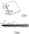
optical coupler 16 follows. Thelight emitters 44 extend for a predetermined length upon thewafer 46. Theinput end 38 is sized to extend substantially the length of the emitters.Angle 54 andangle 52 are chosen to direct light by total internal reflection tooptical fiber 18. It is preferred that most of light fromemitters 14 is coupled intooptical fiber 18, either directly or through reflection from side surfaces 40, 42. - Referring now to Figure 5, a perspective view of
input end 38 is illustrated. As shown above in a horizontal cross section, lenslets 48 are wedge-shaped. However, light emitted fromlight emitters 44 may diverge in a vertical angle by up to a 45° half angle. Such divergence is characteristic with commonly known laser diodes. Thus, providing merely a wedge-shapedlenslet 48 may not allow all the light to be coupled withincoupler body 30.Lenslets 48 have acurved surface 56 that collimates light in the vertical direction. Also, lenslets 48 may be curved slightly in the horizontal direction to collimate light in the horizontal direction as well. The curvature will vary based upon the position of the lenslet and the light source as would be known to those skilled in the art. - Referring now to Figure 6, a cross-sectional view through line 5-5 illustrates a
lenslet 48 withlight rays 58 that are emitted fromemitter 14 substantially collimated incoupler body 30. - In operation, the number of
emitters 44 and therefore the width ofcoupler body 30 may be adjusted depending on the particular intensity required for the particular application. As one skilled in the art would recognize, the angle of light directed to the surface of optical fiber should not exceed the numerical aperture of the fiber. If varying intensities are required, the controller may be used to selectively operate certain emitters. As the width is adjusted the angles of the lenslets are also adjusted to direct light to theface 50 ofoptical fiber 18. In a motor vehicleseveral couplers 30 and severallight sources 14 may be employed. All the light sources and couplers may be maintained in a central location and a plurality ofoptical fibers 18 may be routed throughout the vehicle where light is desired. - While particular embodiments of the invention have been shown and described, numerous variations and alternate embodiments will occur to those skilled in the art. Accordingly, it is intended that the invention be limited only in terms of the appended claims.
Claims (9)
- A lighting system comprising:a plurality of light sources generating a light;an optical fiber; anda light coupler optically coupling said light sources to said fiber, said coupler having a body and a plurality of lenslets corresponding to a respective light source, each lenslet directing light through the body to said optical fiber.
- A lighting system as recited in claim 1 wherein said body has sides with a predetermined angle with respect to a face of said optical fiber.
- A lighting system as recited in claim 1 wherein the light sources comprise laser diodes.
- A lighting system as recited in claim 1 wherein the light sources comprise a wafer having a plurality of laser cavities.
- A lighting system as recited in claim 1 wherein each of said plurality of lenslets have a wedge shape.
- A lighting system as recited in claim 5 wherein said wedge shape has an angle directing light to a face of said optical fiber.
- A lighting system as recited in claim 6 wherein said angle increases as a distance from a center emitter increases.
- A lighting system as recited in claim 1 wherein said plurality of lenslets collimated light in a first direction.
- A lighting system as recited in claim 1 wherein said plurality of lenslets have a curved cross section.
Applications Claiming Priority (2)
| Application Number | Priority Date | Filing Date | Title |
|---|---|---|---|
| US410952 | 1989-09-22 | ||
| US09/410,952 US7027691B1 (en) | 1999-10-05 | 1999-10-05 | Light coupling and distribution system |
Publications (2)
| Publication Number | Publication Date |
|---|---|
| EP1091166A1 true EP1091166A1 (en) | 2001-04-11 |
| EP1091166B1 EP1091166B1 (en) | 2005-11-16 |
Family
ID=23626940
Family Applications (1)
| Application Number | Title | Priority Date | Filing Date |
|---|---|---|---|
| EP00308171A Expired - Lifetime EP1091166B1 (en) | 1999-10-05 | 2000-09-19 | Light coupling and distribution system |
Country Status (4)
| Country | Link |
|---|---|
| US (1) | US7027691B1 (en) |
| EP (1) | EP1091166B1 (en) |
| JP (1) | JP2001116963A (en) |
| DE (1) | DE60024031T2 (en) |
Cited By (2)
| Publication number | Priority date | Publication date | Assignee | Title |
|---|---|---|---|---|
| WO2004057384A1 (en) * | 2002-12-20 | 2004-07-08 | Koninklijke Philips Electronics N.V. | Apparatus and method for illuminating a rod |
| EP2028510A2 (en) | 2007-03-26 | 2009-02-25 | Schott AG | Lighting device, in particular for vehicles |
Families Citing this family (2)
| Publication number | Priority date | Publication date | Assignee | Title |
|---|---|---|---|---|
| DE10323857A1 (en) * | 2003-05-26 | 2005-01-27 | Osram Opto Semiconductors Gmbh | Housing for a laser diode device, laser diode device and method of manufacturing a laser diode device |
| US7444046B2 (en) * | 2005-10-18 | 2008-10-28 | Nlight Photonics Corporation | Diode laser array coupling optic and system |
Citations (5)
| Publication number | Priority date | Publication date | Assignee | Title |
|---|---|---|---|---|
| EP0596865A2 (en) * | 1990-12-17 | 1994-05-11 | Stanley Electric Co., Ltd. | Light irradiating apparatus having light emitting diode used as light source |
| DE19542416A1 (en) * | 1994-11-17 | 1996-05-23 | Teledyne Ind | Arrangement for generating a directed light radiation from an LED |
| WO1998002690A1 (en) * | 1996-07-12 | 1998-01-22 | Alliedsignal Inc. | Illumination sources and systems |
| WO1998033007A1 (en) * | 1997-01-23 | 1998-07-30 | Koninklijke Philips Electronics N.V. | Luminaire |
| WO2000036336A1 (en) * | 1998-12-17 | 2000-06-22 | Koninklijke Philips Electronics N.V. | Light engine |
Family Cites Families (15)
| Publication number | Priority date | Publication date | Assignee | Title |
|---|---|---|---|---|
| US4389085A (en) * | 1978-02-22 | 1983-06-21 | Kei Mori | Lighting system utilizing the sunlight |
| US4496211A (en) | 1980-12-05 | 1985-01-29 | Maurice Daniel | Lightpipe network with optical devices for distributing electromagnetic radiation |
| FR2641434B1 (en) | 1988-12-30 | 1991-03-15 | Thomson Csf | INFORMATION TRANSMISSION DEVICE USING STATISTICAL CODING |
| GB9003097D0 (en) | 1990-02-12 | 1990-04-11 | Scient Generics Ltd | Solid state laser diode light source |
| EP0541658B2 (en) | 1990-08-01 | 2004-01-21 | Diomed Limited | High power light source |
| US5081639A (en) | 1990-10-01 | 1992-01-14 | The United States Of America As Represented By The United States Department Of Energy | Laser diode assembly including a cylindrical lens |
| US5155631A (en) | 1990-10-01 | 1992-10-13 | The United States Of America As Represented By The Department Of Energy | Method for fabrication of cylindrical microlenses of selected shape |
| US5135590A (en) * | 1991-05-24 | 1992-08-04 | At&T Bell Laboratories | Optical fiber alignment method |
| JPH07281053A (en) * | 1994-04-11 | 1995-10-27 | Mitsui Petrochem Ind Ltd | Fiber optic coupler |
| US5589684A (en) | 1994-06-28 | 1996-12-31 | Sdl, Inc. | Multiple diode lasers stabilized with a fiber grating |
| US6152588A (en) * | 1994-09-28 | 2000-11-28 | Sdl, Inc. | Addressable vehicular lighting system |
| US5844723A (en) | 1997-04-11 | 1998-12-01 | Blue Sky Research | Laser diode assembly including a carrier-mounted crossed pair of cylindrical microlenses |
| US6034779A (en) * | 1997-08-08 | 2000-03-07 | Hoya Corporation | Array element examination method and array element examination device |
| US6625350B2 (en) * | 2001-01-22 | 2003-09-23 | Osaki Electric Co., Ltd. | Fiber collimator array |
| US6587618B2 (en) * | 2001-03-16 | 2003-07-01 | Corning Incorporated | Collimator array and method and system for aligning optical fibers to a lens array |
-
1999
- 1999-10-05 US US09/410,952 patent/US7027691B1/en not_active Expired - Fee Related
-
2000
- 2000-09-19 EP EP00308171A patent/EP1091166B1/en not_active Expired - Lifetime
- 2000-09-19 DE DE60024031T patent/DE60024031T2/en not_active Expired - Fee Related
- 2000-10-05 JP JP2000305695A patent/JP2001116963A/en active Pending
Patent Citations (5)
| Publication number | Priority date | Publication date | Assignee | Title |
|---|---|---|---|---|
| EP0596865A2 (en) * | 1990-12-17 | 1994-05-11 | Stanley Electric Co., Ltd. | Light irradiating apparatus having light emitting diode used as light source |
| DE19542416A1 (en) * | 1994-11-17 | 1996-05-23 | Teledyne Ind | Arrangement for generating a directed light radiation from an LED |
| WO1998002690A1 (en) * | 1996-07-12 | 1998-01-22 | Alliedsignal Inc. | Illumination sources and systems |
| WO1998033007A1 (en) * | 1997-01-23 | 1998-07-30 | Koninklijke Philips Electronics N.V. | Luminaire |
| WO2000036336A1 (en) * | 1998-12-17 | 2000-06-22 | Koninklijke Philips Electronics N.V. | Light engine |
Cited By (4)
| Publication number | Priority date | Publication date | Assignee | Title |
|---|---|---|---|---|
| WO2004057384A1 (en) * | 2002-12-20 | 2004-07-08 | Koninklijke Philips Electronics N.V. | Apparatus and method for illuminating a rod |
| EP2028510A2 (en) | 2007-03-26 | 2009-02-25 | Schott AG | Lighting device, in particular for vehicles |
| EP2028510A3 (en) * | 2007-03-26 | 2010-01-06 | Schott AG | Lighting device, in particular for vehicles |
| US7942562B2 (en) | 2007-03-26 | 2011-05-17 | Schott Ag | Illumination device, in particular for vehicles |
Also Published As
| Publication number | Publication date |
|---|---|
| US7027691B1 (en) | 2006-04-11 |
| DE60024031D1 (en) | 2005-12-22 |
| JP2001116963A (en) | 2001-04-27 |
| DE60024031T2 (en) | 2006-07-13 |
| EP1091166B1 (en) | 2005-11-16 |
Similar Documents
| Publication | Publication Date | Title |
|---|---|---|
| US5700078A (en) | Laser illuminated lighting system | |
| US5890796A (en) | Laser illuminated lighting system utilizing a diffractive optical element | |
| US5365412A (en) | Low profile illuminator | |
| EP0940625B1 (en) | A dimpled manifold optical element for a vehicle lighting system | |
| US5295047A (en) | Line-of-light illuminating device | |
| US5438485A (en) | Illuminator for use with a remote light source | |
| US5434754A (en) | Light manifold | |
| US5791757A (en) | Vehicle lighting system utilizing a uniform thickness thin sheet optical element | |
| US7773655B2 (en) | High brightness laser diode module | |
| US5825051A (en) | Optoelectronic component with central hollow | |
| US6520666B1 (en) | Apparatus for lighting spaces, bodies or surfaces | |
| US6824284B2 (en) | Edge-lit optical element having a manifold and lamp assembly utilizing such element | |
| US5857770A (en) | Laser illuminated vehicle lighting system utilizing a turning prism | |
| CN103885116B (en) | Optical conductor with band-like light gasing surface | |
| US5321586A (en) | Lighting device for a vehicle having at least one central light source | |
| US9377170B2 (en) | Motor vehicle lighting device with an optical fiber having a coupling lens and a transport and conversion lens | |
| EP0532262B1 (en) | Projection headlamp lighting system using different diameter optical light conductors | |
| JP4664662B2 (en) | Signal or lighting equipment for automobiles | |
| CA2057084C (en) | Light irradiating apparatus having light emitting diode used as light source | |
| USRE34318E (en) | Lighting systems employing optical fibers | |
| CN211345145U (en) | Optical system and vehicle | |
| JP2023525497A (en) | Automotive lighting system | |
| US7367702B2 (en) | Headlight | |
| JP2008518411A (en) | Vehicle light | |
| US7027691B1 (en) | Light coupling and distribution system |
Legal Events
| Date | Code | Title | Description |
|---|---|---|---|
| PUAI | Public reference made under article 153(3) epc to a published international application that has entered the european phase |
Free format text: ORIGINAL CODE: 0009012 |
|
| AK | Designated contracting states |
Kind code of ref document: A1 Designated state(s): DE FR GB |
|
| AX | Request for extension of the european patent |
Free format text: AL;LT;LV;MK;RO;SI |
|
| 17P | Request for examination filed |
Effective date: 20011008 |
|
| AKX | Designation fees paid |
Free format text: DE FR GB |
|
| 17Q | First examination report despatched |
Effective date: 20031031 |
|
| GRAP | Despatch of communication of intention to grant a patent |
Free format text: ORIGINAL CODE: EPIDOSNIGR1 |
|
| GRAS | Grant fee paid |
Free format text: ORIGINAL CODE: EPIDOSNIGR3 |
|
| GRAA | (expected) grant |
Free format text: ORIGINAL CODE: 0009210 |
|
| AK | Designated contracting states |
Kind code of ref document: B1 Designated state(s): DE FR GB |
|
| REG | Reference to a national code |
Ref country code: GB Ref legal event code: FG4D |
|
| REF | Corresponds to: |
Ref document number: 60024031 Country of ref document: DE Date of ref document: 20051222 Kind code of ref document: P |
|
| ET | Fr: translation filed | ||
| PLBE | No opposition filed within time limit |
Free format text: ORIGINAL CODE: 0009261 |
|
| STAA | Information on the status of an ep patent application or granted ep patent |
Free format text: STATUS: NO OPPOSITION FILED WITHIN TIME LIMIT |
|
| 26N | No opposition filed |
Effective date: 20060817 |
|
| PGFP | Annual fee paid to national office [announced via postgrant information from national office to epo] |
Ref country code: GB Payment date: 20070914 Year of fee payment: 8 |
|
| PGFP | Annual fee paid to national office [announced via postgrant information from national office to epo] |
Ref country code: FR Payment date: 20070914 Year of fee payment: 8 |
|
| PGFP | Annual fee paid to national office [announced via postgrant information from national office to epo] |
Ref country code: DE Payment date: 20080919 Year of fee payment: 9 |
|
| GBPC | Gb: european patent ceased through non-payment of renewal fee |
Effective date: 20080919 |
|
| REG | Reference to a national code |
Ref country code: FR Ref legal event code: ST Effective date: 20090529 |
|
| PG25 | Lapsed in a contracting state [announced via postgrant information from national office to epo] |
Ref country code: FR Free format text: LAPSE BECAUSE OF NON-PAYMENT OF DUE FEES Effective date: 20080930 |
|
| PG25 | Lapsed in a contracting state [announced via postgrant information from national office to epo] |
Ref country code: GB Free format text: LAPSE BECAUSE OF NON-PAYMENT OF DUE FEES Effective date: 20080919 |
|
| PG25 | Lapsed in a contracting state [announced via postgrant information from national office to epo] |
Ref country code: DE Free format text: LAPSE BECAUSE OF NON-PAYMENT OF DUE FEES Effective date: 20100401 |