EP1092077B1 - Systeme de fraisage permettant de former une fenetre dans la paroi d'un tubulaire - Google Patents
Systeme de fraisage permettant de former une fenetre dans la paroi d'un tubulaire Download PDFInfo
- Publication number
- EP1092077B1 EP1092077B1 EP99931252A EP99931252A EP1092077B1 EP 1092077 B1 EP1092077 B1 EP 1092077B1 EP 99931252 A EP99931252 A EP 99931252A EP 99931252 A EP99931252 A EP 99931252A EP 1092077 B1 EP1092077 B1 EP 1092077B1
- Authority
- EP
- European Patent Office
- Prior art keywords
- milling
- milling tool
- window
- casing
- guiding device
- Prior art date
- Legal status (The legal status is an assumption and is not a legal conclusion. Google has not performed a legal analysis and makes no representation as to the accuracy of the status listed.)
- Expired - Lifetime
Links
- 238000003801 milling Methods 0.000 title claims abstract description 63
- 230000015572 biosynthetic process Effects 0.000 claims abstract description 5
- 239000012530 fluid Substances 0.000 claims description 9
- 238000005520 cutting process Methods 0.000 claims description 3
- 230000005540 biological transmission Effects 0.000 claims description 2
- 238000004891 communication Methods 0.000 claims description 2
- 230000001419 dependent effect Effects 0.000 claims 1
- 239000004215 Carbon black (E152) Substances 0.000 description 1
- 229910000831 Steel Inorganic materials 0.000 description 1
- 238000005452 bending Methods 0.000 description 1
- 238000005516 engineering process Methods 0.000 description 1
- 229930195733 hydrocarbon Natural products 0.000 description 1
- 150000002430 hydrocarbons Chemical class 0.000 description 1
- 238000000034 method Methods 0.000 description 1
- 230000002250 progressing effect Effects 0.000 description 1
- 239000010959 steel Substances 0.000 description 1
Images
Classifications
-
- E—FIXED CONSTRUCTIONS
- E21—EARTH OR ROCK DRILLING; MINING
- E21B—EARTH OR ROCK DRILLING; OBTAINING OIL, GAS, WATER, SOLUBLE OR MELTABLE MATERIALS OR A SLURRY OF MINERALS FROM WELLS
- E21B29/00—Cutting or destroying pipes, packers, plugs or wire lines, located in boreholes or wells, e.g. cutting of damaged pipes, of windows; Deforming of pipes in boreholes or wells; Reconditioning of well casings while in the ground
- E21B29/06—Cutting windows, e.g. directional window cutters for whipstock operations
-
- E—FIXED CONSTRUCTIONS
- E21—EARTH OR ROCK DRILLING; MINING
- E21B—EARTH OR ROCK DRILLING; OBTAINING OIL, GAS, WATER, SOLUBLE OR MELTABLE MATERIALS OR A SLURRY OF MINERALS FROM WELLS
- E21B7/00—Special methods or apparatus for drilling
- E21B7/04—Directional drilling
- E21B7/06—Deflecting the direction of boreholes
- E21B7/061—Deflecting the direction of boreholes the tool shaft advancing relative to a guide, e.g. a curved tube or a whipstock
Definitions
- the present invention relates to a system for milling a window in a casing arranged in a borehole formed in an earth formation according to the preamble of claim 1.
- a milling system is known from EP-A-0 791 722.
- a window is created by fixedly positioning a whipstock having a slanted guide-way, within the casing and guiding a milling tool along the guide-way during milling of the window.
- the downhole force required to progress the milling tool along the guide-way is supplied from surface via a pipe string connected to the milling tool. Fluid is pumped through the pipe string to operate the milling tool and to remove the milling cuttings from the borehole.
- a problem of the conventional system for milling a window in a casing is that the downhole force required to progress the milling tool along the guide-way is insufficiently controllable. This is, for example, due to frictional forces which counter-act the downward force acting on the pipe string, and due to uncontrolled bending of the pipe string within the casing.
- the thrust force necessary for progressing the milling tool during milling is provided from the guiding device rather than from surface.
- the guiding device can be provided with a hydraulic motor or an electric motor receiving power from surface via a suitable control system.
- casing refers to any elongate hollow element which is arranged in the borehole and in which a window is to be milled, such as a cemented casing or a wellbore liner.
- the guiding device is provided with a guide-way defining said selected path and with means for preventing movement of the milling tool transverse to the guide-way. In this manner it is achieved that undesired "walk” of the mill during milling is prevented and that an accurate shape of the window is obtained.
- the selected path extends substantially parallel to the longitudinal axis of the casing.
- the upper window portion is milled by the upper side of the mill and the lower window portion by the lower side of the mill.
- the upper window portion will be biased in one direction (depending on the direction of rotation of the mill) and the lower window portion in the other direction.
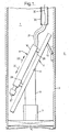
- a borehole 1 has been formed in an earth formation 2 and provided with a steel casing 3.
- the embodiment 4 of the system according to the invention includes a retrievable downhole packer 5 fixedly positioned at a selected location in the casing 3 and provided with an upwardly extending latching element 7 adapted to receive and fixedly hold a support column 9 of a guiding device 11 in a selected orientation.
- the guiding device 11 includes a ramp element 14 rigidly connected to the support column 9 and provided with a secondary support element 16 which is radially extendible against the inner surface of the casing 3.
- the ramp element 14 extends inclined relative to the longitudinal axis of the casing 3 and defines inclined, opposite, directions 20, 22 of a path along which a milling tool 18 is movable, direction 20 being inclined downwardly and direction 22 being inclined upwardly.
- the ramp element 14 is internally provided with a thrust means in the form of a chain (not shown) movable in the directions 20,22 and an electric motor (not shown) for driving the chain.
- the milling tool 18 has legs 24, 26 which are connected to the chain so that movement of the chain in directions 20, 22 results in corresponding movement of the milling tool 18.
- the milling tool is internally provided with a hydraulic motor (not shown) for driving a mill 27 of the milling tool, the hydraulic motor receiving hydraulic fluid via a coiled tubing 30 extending through the casing 3 to a hydraulic pump (not shown) at surface, the coiled tubing being connected to the hydraulic motor by means of a flexible hose 31.
- the mill 27 has a plurality of outlet nozzles (not shown) for hydraulic fluid from the motor.
- the coiled tubing is provided with.a connector (not shown) for connecting the coiled tubing to the guiding device 11 so as to lower and retrieve the guiding device 11 and milling tool 18 through the wellbore 1.
- An electric power supply cable 32 extends from a control unit (not shown) at surface, through the coiled tubing 30 and the hose 31, to the milling tool 18 and from there via one of the legs 24, 26 to the electric motor of the ramp element 14.
- the control unit is provided with controls for selectively moving the chain in direction 20 or 22.
- the control unit includes a control for selectively extending or refracting the secondary support element 16 relative to the inner surface of the casing 3.
- the packer 5 with the latching element connected thereto is fixedly positioned at a selected location in the casing 3 at an orientation corresponding to the desired orientation of the window to be milled.
- the guiding device 11 is connected to the coiled tubing 30 by means of the connector and the combined guiding device 11/milling tool 18 are then lowered by coiled tubing 30 through the casing 3.until the support column 9 latches into latching element 7. Subsequently the control unit at surface is operated to provide a control signal via power supply cable 32 to the guiding device so as to radially extended support element 16 against the casing 3.
- Hydraulic fluid is then pumped through the coiled tubing 30 thereby driving the hydraulic motor so as to rotate the mill 27.
- the control unit at surface is operated so as to move the chain and the milling tool 18 in the direction 20 in order to mill the window.
- the cuttings resulting from the milling operation are entrained and transported away by the hydraulic fluid exiting through the nozzles of the mill 27.
- the control unit is operated zo move the milling tool 18 in direction 22 away from the casing 3 and to retract the support element 16.
- the combined guiding device 11/milling tool 18 are then retrieved to surface by means of the coiled tubing 30.
- the packer 5 and latching element 7 are subsequently retrieved to surface in any suitable manner.
- these devices can be integrated into one tool, optionally also including the packer and latching element.
- the thrust means is one of a worm-gear having a spindle extending in the direction along which the milling tool is guided and a hydraulic piston/cylinder assembly extendible in said direction.
- the milling device can be provided with measuring means for measuring parameters such as the torque delivered by the output shaft of the milling tool, the thrust force delivered by the thrust means, and the position of the milling tool along said path.
- the measuring means is in communication with a data receiving station at surface via a data transmission cable extending through a tubing, e.g. the coiled tubing referred to above.
Landscapes
- Geology (AREA)
- Life Sciences & Earth Sciences (AREA)
- Engineering & Computer Science (AREA)
- Mining & Mineral Resources (AREA)
- Environmental & Geological Engineering (AREA)
- Fluid Mechanics (AREA)
- Physics & Mathematics (AREA)
- General Life Sciences & Earth Sciences (AREA)
- Geochemistry & Mineralogy (AREA)
- Earth Drilling (AREA)
- Drilling And Boring (AREA)
- Window Of Vehicle (AREA)
- Glass Compositions (AREA)
- Wing Frames And Configurations (AREA)
Abstract
Claims (11)
- Système pour fraiser une fenêtre dans un cuvelage aménagé dans un trou de forage formé dans une formation terrestre, le système comprenant un outil de fraisage (18) pour fraiser cette fenêtre, un dispositif de guidage (19) pour guider l'outil de fraisage le long d'un trajet choisi dans le cuvelage au cours du fraisage de cette fenêtre, le dispositif de guidage ayant des moyens (5 à 9) pour aménager de manière fixe le dispositif de guidage dans le cuvelage, dans lequel le dispositif de guidage est muni d'un moyen de poussée pour pousser l'outil de fraisage le long du trajet choisi au cours du fraisage de cette fenêtre, un moteur étant également aménagé de façon à entraîner une fraise (27) de l'outil de fraisage,
caractérisé en ce que le moteur et le moyen de poussée sont aménagés de sorte que le fonctionnement du moyen de poussée amène à la fois le moteur et l'outil de fraisage à être poussés ensemble le long dudit trajet choisi. - Système selon la revendication 1, dans lequel le moyen de poussée comprend un moyen quelconque choisi parmi une chaîne mobile dans la direction dudit trajet, une transmission à vis sans fin ayant un axe s'étendant dans la direction dudit trajet et un assemblage hydraulique à piston/cylindre pouvant s'étendre dans la direction dudit trajet.
- Système selon la revendication 1 ou 2, dans lequel le dispositif de guidage (11) est pourvu d'une voie de guidage définissant ledit trajet choisi et de moyens pour empêcher un mouvement de l'outil de fraisage transversalement à la voie de guidage.
- Système selon l'une quelconque des revendications 1 à 3, dans lequel ledit trajet choisi s'étend sensiblement parallèlement à l'axe longitudinal du cuvelage.
- Système selon l'une quelconque des revendications 1 à 4, dans lequel l'outil de fraisage (18) a un arbre de sortie entraîné par un moteur hydraulique, le moteur hydraulique étant raccordé à une alimentation en fluide hydraulique par une ligne de tubes (31) s'étendant à travers le cuvelage vers la surface et ayant une ouverture de sortie pour le fluide hydraulique aménagée pour permettre au fluide hydraulique d'entraîner des débris provenant du fraisage de la fenêtre.
- Système selon la revendication 5, dans lequel le moyen de poussée est entraîné par un moteur électrique connecté à un câble d'alimentation électrique (32) s'étendant à travers ladite ligne de tubes.
- Système selon la revendication 5 ou 6, dans lequel la ligne de tubes est une ligne de tubes enroulés.
- Système selon l'une quelconque des revendications 1 à 7, dans lequel le dispositif de fraisage est muni d'un moyen de mesure pour mesurer au moins un paramètre parmi le couple de torsion délivré par un arbre de sortie de l'outil de fraisage, la force de poussée délivrée par le moyen de poussée et la position de l'outil de fraisage le long dudit trajet.
- Système selon la revendication 8 lorsqu'elle dépend de la revendication 5, dans lequel le moyen de mesure est en communication avec un poste de réception de données en surface via un câble de transmission de données s'étendant à travers ladite ligne de tubes.
- Système selon l'une quelconque des revendications 1 à 9, comprenant en outre un dispositif de mouvement intermittent pour orienter l'outil de fraisage dans différentes orientations par rapport au dispositif de guidage de manière à permettre de fraiser la fenêtre en de multiples passes de l'outil de fraisage, chaque passe correspondant à l'une desdites orientations de l'outil de fraisage par rapport au dispositif de guidage.
- Système selon l'une quelconque des revendications 1 à 10, dans lequel le trajet choisi s'étend sensiblement dans la direction longitudinale du cuvelage.
Priority Applications (1)
| Application Number | Priority Date | Filing Date | Title |
|---|---|---|---|
| EP99931252A EP1092077B1 (fr) | 1998-07-02 | 1999-06-30 | Systeme de fraisage permettant de former une fenetre dans la paroi d'un tubulaire |
Applications Claiming Priority (4)
| Application Number | Priority Date | Filing Date | Title |
|---|---|---|---|
| EP98305275 | 1998-07-02 | ||
| EP98305275 | 1998-07-02 | ||
| EP99931252A EP1092077B1 (fr) | 1998-07-02 | 1999-06-30 | Systeme de fraisage permettant de former une fenetre dans la paroi d'un tubulaire |
| PCT/EP1999/004700 WO2000001921A1 (fr) | 1998-07-02 | 1999-06-30 | Systeme de fraisage permettant de former une fenetre dans la paroi d'un tubulaire |
Publications (2)
| Publication Number | Publication Date |
|---|---|
| EP1092077A1 EP1092077A1 (fr) | 2001-04-18 |
| EP1092077B1 true EP1092077B1 (fr) | 2006-10-11 |
Family
ID=8234910
Family Applications (1)
| Application Number | Title | Priority Date | Filing Date |
|---|---|---|---|
| EP99931252A Expired - Lifetime EP1092077B1 (fr) | 1998-07-02 | 1999-06-30 | Systeme de fraisage permettant de former une fenetre dans la paroi d'un tubulaire |
Country Status (8)
| Country | Link |
|---|---|
| EP (1) | EP1092077B1 (fr) |
| AR (1) | AR019187A1 (fr) |
| AU (1) | AU751528B2 (fr) |
| CA (1) | CA2336326C (fr) |
| DE (1) | DE69933564T2 (fr) |
| GC (1) | GC0000060A (fr) |
| NO (1) | NO317380B1 (fr) |
| WO (1) | WO2000001921A1 (fr) |
Families Citing this family (1)
| Publication number | Priority date | Publication date | Assignee | Title |
|---|---|---|---|---|
| JP2004196626A (ja) | 2002-12-20 | 2004-07-15 | Sumitomo Chem Co Ltd | 酸化チタンの製造方法 |
Family Cites Families (6)
| Publication number | Priority date | Publication date | Assignee | Title |
|---|---|---|---|---|
| US2539047A (en) * | 1946-06-17 | 1951-01-23 | Arutunoff Armais | Side drill |
| US2631821A (en) * | 1952-02-28 | 1953-03-17 | Joe P Caldwell | Directional drilling device |
| FR2091931B1 (fr) * | 1970-05-15 | 1973-08-10 | Petroles Cie Francaise | |
| US4007797A (en) * | 1974-06-04 | 1977-02-15 | Texas Dynamatics, Inc. | Device for drilling a hole in the side wall of a bore hole |
| US4640353A (en) * | 1986-03-21 | 1987-02-03 | Atlantic Richfield Company | Electrode well and method of completion |
| US5687806A (en) * | 1996-02-20 | 1997-11-18 | Gas Research Institute | Method and apparatus for drilling with a flexible shaft while using hydraulic assistance |
-
1999
- 1999-06-27 GC GCP1999193 patent/GC0000060A/xx active
- 1999-06-30 DE DE69933564T patent/DE69933564T2/de not_active Expired - Fee Related
- 1999-06-30 CA CA002336326A patent/CA2336326C/fr not_active Expired - Fee Related
- 1999-06-30 EP EP99931252A patent/EP1092077B1/fr not_active Expired - Lifetime
- 1999-06-30 AR ARP990103173 patent/AR019187A1/es active IP Right Grant
- 1999-06-30 AU AU47817/99A patent/AU751528B2/en not_active Ceased
- 1999-06-30 WO PCT/EP1999/004700 patent/WO2000001921A1/fr not_active Ceased
-
2000
- 2000-12-29 NO NO20006696A patent/NO317380B1/no unknown
Also Published As
| Publication number | Publication date |
|---|---|
| CA2336326A1 (fr) | 2000-01-13 |
| CA2336326C (fr) | 2007-08-28 |
| AR019187A1 (es) | 2001-12-26 |
| NO317380B1 (no) | 2004-10-18 |
| AU4781799A (en) | 2000-01-24 |
| AU751528B2 (en) | 2002-08-22 |
| WO2000001921A1 (fr) | 2000-01-13 |
| DE69933564D1 (de) | 2006-11-23 |
| NO20006696D0 (no) | 2000-12-29 |
| DE69933564T2 (de) | 2007-06-21 |
| GC0000060A (en) | 2004-06-30 |
| NO20006696L (no) | 2001-02-28 |
| EP1092077A1 (fr) | 2001-04-18 |
Similar Documents
| Publication | Publication Date | Title |
|---|---|---|
| CA2271401C (fr) | Forage avec tubage | |
| EP0695390B1 (fr) | Dispositif de deviation de forage | |
| CN101443526B (zh) | 方向控制钻井系统 | |
| CA2136559C (fr) | Dispositif de forage fond de trou | |
| CA2371133C (fr) | Procede de creation d'un trou de forage | |
| US20050150692A1 (en) | Directional cased hole side track method applying rotary closed loop system and casing mill | |
| CA2207923C (fr) | Systeme de forage orientable a moteur de fond de puits | |
| US6581690B2 (en) | Window cutting tool for well casing | |
| EP1764475B1 (fr) | Système de forage et méthodes de forage des puits latéraux | |
| US20010011591A1 (en) | Guide device | |
| CA2445085A1 (fr) | Procede pour realiser un trou de forage d'un rayon tres petit | |
| US20130292180A1 (en) | Steerable Gas Turbodrill | |
| WO1996005402A1 (fr) | Outil de forage souterrain orientable | |
| EP1092077B1 (fr) | Systeme de fraisage permettant de former une fenetre dans la paroi d'un tubulaire | |
| AU731454B2 (en) | System for cutting materials in wellbores | |
| CN100360762C (zh) | 定向钻孔组件及定向钻孔设备 | |
| US20060137912A1 (en) | Method and apparatus for horizontal drilling and oil recovery | |
| CA2161536C (fr) | Dispositif d'amorcage de deviations | |
| US20050167160A1 (en) | Method and apparatus for horizontal drilling and oil recovery | |
| GB2354546A (en) | A method for disengaging a support member embedded in the seabed |
Legal Events
| Date | Code | Title | Description |
|---|---|---|---|
| PUAI | Public reference made under article 153(3) epc to a published international application that has entered the european phase |
Free format text: ORIGINAL CODE: 0009012 |
|
| 17P | Request for examination filed |
Effective date: 20001230 |
|
| AK | Designated contracting states |
Kind code of ref document: A1 Designated state(s): DE GB NL |
|
| GRAP | Despatch of communication of intention to grant a patent |
Free format text: ORIGINAL CODE: EPIDOSNIGR1 |
|
| GRAS | Grant fee paid |
Free format text: ORIGINAL CODE: EPIDOSNIGR3 |
|
| GRAA | (expected) grant |
Free format text: ORIGINAL CODE: 0009210 |
|
| AK | Designated contracting states |
Kind code of ref document: B1 Designated state(s): DE GB NL |
|
| REG | Reference to a national code |
Ref country code: GB Ref legal event code: FG4D |
|
| REF | Corresponds to: |
Ref document number: 69933564 Country of ref document: DE Date of ref document: 20061123 Kind code of ref document: P |
|
| PLBE | No opposition filed within time limit |
Free format text: ORIGINAL CODE: 0009261 |
|
| STAA | Information on the status of an ep patent application or granted ep patent |
Free format text: STATUS: NO OPPOSITION FILED WITHIN TIME LIMIT |
|
| 26N | No opposition filed |
Effective date: 20070712 |
|
| PGFP | Annual fee paid to national office [announced via postgrant information from national office to epo] |
Ref country code: NL Payment date: 20080630 Year of fee payment: 10 Ref country code: DE Payment date: 20080630 Year of fee payment: 10 |
|
| PGFP | Annual fee paid to national office [announced via postgrant information from national office to epo] |
Ref country code: GB Payment date: 20080529 Year of fee payment: 10 |
|
| GBPC | Gb: european patent ceased through non-payment of renewal fee |
Effective date: 20090630 |
|
| NLV4 | Nl: lapsed or anulled due to non-payment of the annual fee |
Effective date: 20100101 |
|
| PG25 | Lapsed in a contracting state [announced via postgrant information from national office to epo] |
Ref country code: GB Free format text: LAPSE BECAUSE OF NON-PAYMENT OF DUE FEES Effective date: 20090630 |
|
| PG25 | Lapsed in a contracting state [announced via postgrant information from national office to epo] |
Ref country code: DE Free format text: LAPSE BECAUSE OF NON-PAYMENT OF DUE FEES Effective date: 20100101 |
|
| PG25 | Lapsed in a contracting state [announced via postgrant information from national office to epo] |
Ref country code: NL Free format text: LAPSE BECAUSE OF NON-PAYMENT OF DUE FEES Effective date: 20100101 |