EP1092476A1 - Schneidmühle - Google Patents
Schneidmühle Download PDFInfo
- Publication number
- EP1092476A1 EP1092476A1 EP20000122110 EP00122110A EP1092476A1 EP 1092476 A1 EP1092476 A1 EP 1092476A1 EP 20000122110 EP20000122110 EP 20000122110 EP 00122110 A EP00122110 A EP 00122110A EP 1092476 A1 EP1092476 A1 EP 1092476A1
- Authority
- EP
- European Patent Office
- Prior art keywords
- stator
- cutting
- rotor
- cutting element
- mill according
- Prior art date
- Legal status (The legal status is an assumption and is not a legal conclusion. Google has not performed a legal analysis and makes no representation as to the accuracy of the status listed.)
- Granted
Links
- 239000004033 plastic Substances 0.000 claims description 8
- 229920003023 plastic Polymers 0.000 claims description 8
- 238000002347 injection Methods 0.000 claims description 2
- 239000007924 injection Substances 0.000 claims description 2
- 208000015943 Coeliac disease Diseases 0.000 claims 1
- 230000002996 emotional effect Effects 0.000 claims 1
- 238000010438 heat treatment Methods 0.000 claims 1
- 239000000428 dust Substances 0.000 description 7
- 239000000969 carrier Substances 0.000 description 4
- 239000008187 granular material Substances 0.000 description 2
- 238000004519 manufacturing process Methods 0.000 description 2
- 230000015572 biosynthetic process Effects 0.000 description 1
- 230000000295 complement effect Effects 0.000 description 1
- 230000000694 effects Effects 0.000 description 1
- 239000002440 industrial waste Substances 0.000 description 1
- 238000001746 injection moulding Methods 0.000 description 1
- 238000000034 method Methods 0.000 description 1
- 230000036346 tooth eruption Effects 0.000 description 1
Images


Classifications
-
- B—PERFORMING OPERATIONS; TRANSPORTING
- B29—WORKING OF PLASTICS; WORKING OF SUBSTANCES IN A PLASTIC STATE IN GENERAL
- B29B—PREPARATION OR PRETREATMENT OF THE MATERIAL TO BE SHAPED; MAKING GRANULES OR PREFORMS; RECOVERY OF PLASTICS OR OTHER CONSTITUENTS OF WASTE MATERIAL CONTAINING PLASTICS
- B29B17/00—Recovery of plastics or other constituents of waste material containing plastics
- B29B17/04—Disintegrating plastics, e.g. by milling
-
- B—PERFORMING OPERATIONS; TRANSPORTING
- B02—CRUSHING, PULVERISING, OR DISINTEGRATING; PREPARATORY TREATMENT OF GRAIN FOR MILLING
- B02C—CRUSHING, PULVERISING, OR DISINTEGRATING IN GENERAL; MILLING GRAIN
- B02C18/00—Disintegrating by knives or other cutting or tearing members which chop material into fragments
- B02C18/06—Disintegrating by knives or other cutting or tearing members which chop material into fragments with rotating knives
- B02C18/08—Disintegrating by knives or other cutting or tearing members which chop material into fragments with rotating knives within vertical containers
- B02C18/086—Disintegrating by knives or other cutting or tearing members which chop material into fragments with rotating knives within vertical containers specially adapted for disintegrating plastics, e.g. cinematographic films
-
- B—PERFORMING OPERATIONS; TRANSPORTING
- B02—CRUSHING, PULVERISING, OR DISINTEGRATING; PREPARATORY TREATMENT OF GRAIN FOR MILLING
- B02C—CRUSHING, PULVERISING, OR DISINTEGRATING IN GENERAL; MILLING GRAIN
- B02C18/00—Disintegrating by knives or other cutting or tearing members which chop material into fragments
- B02C18/06—Disintegrating by knives or other cutting or tearing members which chop material into fragments with rotating knives
- B02C18/16—Details
- B02C18/18—Knives; Mountings thereof
-
- Y—GENERAL TAGGING OF NEW TECHNOLOGICAL DEVELOPMENTS; GENERAL TAGGING OF CROSS-SECTIONAL TECHNOLOGIES SPANNING OVER SEVERAL SECTIONS OF THE IPC; TECHNICAL SUBJECTS COVERED BY FORMER USPC CROSS-REFERENCE ART COLLECTIONS [XRACs] AND DIGESTS
- Y02—TECHNOLOGIES OR APPLICATIONS FOR MITIGATION OR ADAPTATION AGAINST CLIMATE CHANGE
- Y02W—CLIMATE CHANGE MITIGATION TECHNOLOGIES RELATED TO WASTEWATER TREATMENT OR WASTE MANAGEMENT
- Y02W30/00—Technologies for solid waste management
- Y02W30/50—Reuse, recycling or recovery technologies
- Y02W30/62—Plastics recycling; Rubber recycling
Definitions
- the invention relates to a cutting mill according to the preamble of the claim 1.
- Such cutting mills are for example from DE-A1-3 201 096, DE-A1-3 444 933 and DE-U1-9 200 997 known.
- the well-known granulators either have an operating position in which the stator axis runs horizontally and the regrind is fed radially, or an operating position in which the Stator axis runs vertically and the regrind is fed axially from above.
- the known granulators are mostly with a special pre-cutting chamber provided and are of elongated design. Will these granulators used for crushing the sprue of plastic injection molded parts, so the important thing is to obtain granules that are as dust-free as possible the feed of plastic injection molding machines can be reused can.
- From DE-U1 87 16 200 is a granulator for industrial waste known, in which a driven, rotating, elliptical plate is arranged inclined to the horizontal. This plate can be have cutting teeth on their outer edge, and the funnel can be eccentric be trained.
- the object of the invention is a cutting mill in the preamble of claim 1 to create the type without a special pre-cutting chamber gets along, has a short design and the shredding of the Grist enables a low-dust granulate.
- the rotor cutting element can be fast over the center of the stator Carry out movement with little force to cut the regrind into large pieces break, here the coarse shredding takes place in the chamber in which also the stator cutting elements work, in this chamber can be a very large one Free area that can also hold very bulky regrind. Thereby can also build a relatively small granulator for large regrind become.
- the rotor cutting element is one Approaching the stator cutting element is a great force due to the leverage to disposal.
- the main cutting work takes place in such areas, in which the Grist is cut until it is, for example, over a sieve dust is removed from the stator chamber.
- the cutting elements are simple designed, just trained and can be easily replaced.
- the rotor circumference rolls on Circumference of the stator. This means that there is no separate drive for turning of the rotor is required.
- the rotor can preferably have external teeth and the stator be provided with an internal toothing.
- the number of Stator cutting elements and the ratio of the inner circumference of the stator to Rotor circumference selected such that the rotor cutting element with each rotor revolution one of the stator cutting elements following the next stator cutting element cooperates, with all stator cutting elements in a particular Order to be involved.
- the number of stator cutting elements is preferably eight and the ratio of the inner circumference of the stator to the circumference of the rotor is selected such that the sequence is 1, 6, 3, 8, 5, 2, 7, 4. Because of that the rotor cutting element after each fine cut through the center of the stator chamber the coarse shredding is further improved.
- stator cutting elements and the number of rotor cutting elements can however be chosen as such.
- the ratio of the inner circumference of the stator is preferred chosen for the rotor circumference such that the rotor cutting element each Rotors per rotor revolution with the next stator cutting element cooperates.
- This training is made so that the stator has an inner chamber which is one of the number of Stator cutting elements corresponding number of webs is limited, the Narrow sides each have a certain distance from the narrow sides of the neighboring ones Have webs, and that each stator cutting element on one him associated, frame-shaped cutting element carrier is attached, the two to Pockets for receiving on both sides of the stator cutting element the web ends of two adjacent webs.
- the stator chamber cover can therefore with the stator cutting elements provided cutting element carrier can be easily replaced.
- the cutting element carriers are square, with the corner at one Stator cutting element is arranged and the pockets near the stator cutting element are arranged.
- An advantageous, further embodiment of the invention provides that above the Stator cutting elements a horizontal cutting ring is arranged, the Inner circumference corresponds substantially to the inner circumference of the stator, and that on a horizontal rotor cutting edge is arranged with the rotor, the cutting ring cooperates. This further improves the coarse shredding. In particular, this enables the "capping" of long plastic parts.
- This additional horizontal cutting device made of cutting ring and horizontal rotor cutting edge cuts the regrind with the same, inexpensive, aforementioned Leverage such that it follows immediately between the vertical Cutting elements can be further crushed.
- the horizontal rotor blade is disc-shaped.
- the horizontal cutting edges and the vertical cutting elements stand out by tapering towards each other. This will make the break area reduced when separating and enlarged the area that is cut. As a result, the dust content during the shredding process is kept low.
- the inner stator chamber can also be heated, to reinforce the plastic behavior of the plastics and thus the Reduce dust content again and reduce cutting wear.
- a carrier for the rotor cutting element provided that like the carrier of the stator cutting element is trained. This results in a manufacturing advantage in the Production of the cutting element carrier.
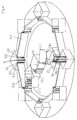
- the cutting mill outlined in FIG. 1 has eight stator cutting elements 1-8 on, each easily exchangeable on the associated stator separator element carriers 1.1-8.1 are attached.
- the stator cutting element carriers 1.1-8.1 are on the inner circumference 9 of a stator 10 arranged evenly distributed.
- the in operational position the vertical mill of the stator is marked with 11.
- the inner chamber of the stator 10 is one of the number of stator cutting elements 1-8 corresponding number of webs 1.2-8.2 limited, the component of the stator 10 and their narrow sides are each a specific one Have distance a to the narrow sides of the adjacent webs.
- the stator cutting element carrier 1.1-8.1 are attached to the webs 1.2-8.2. The Art this attachment and this support will be explained in more detail later.
- a rotor 12 with a circumference 13 is eccentric in the inner chamber of the stator 10 arranged.
- the axis of the rotor 12 is designated 14.
- the scope 13 is considerably smaller than the inner circumference of the stator 9.
- On the rotor 12 is a rotor cutting element carrier 15 is arranged on which one with the Stator cutting elements 1-8 cooperating rotor cutting element 16 attached which is on the circumference 13.
- the rotor 12 rolls with its circumference 13 on the inner circumference 9 of the stator 10.
- the rotor axis 14 guided on a circular path 17 around the stator axis 11. How to run the Rotor 12 takes place, has not been shown.
- stator 1 shows the ratio of the inner circumference of the stator 9 to the circumference of the rotor 13 chosen such that the rotor cutting element 16 per rotor revolution with one of the on the next stator cutting element 2 opposite stator cutting element cooperates, with all stator cutting elements 1-8 in a particular Order to be involved.
- the rotor 12 rolls past the stator cutting elements 2-5 before the rotor cutting element 16 after a rotor revolution on the stator cutting element 6 meets.
- the rotor cutting element 16 is opened meet the stator cutting element 3, etc., so that the specific order to 1, 6, 3, 8, 5, 2, 7, 4 results, then the starting position again 2A is reached.
- FIG. 3 is the path of the rotor cutting element 16 and the rotor cutting element carrier 15 in the phases of FIG. 2 that apply to a rotor revolution, the rotor itself omitted for the sake of clarity has been.
- the rotor cutting element 16 accordingly runs essentially through the middle of the inner stator chamber and breaks a regrind part in area X. 18 into pieces before it cuts pieces of the regrind in the Y area. in the Area X thus undergoes a coarse shredding, while area Y a fine comminution takes place. The latter happens without generating essential dust.
- FIG. 4 shows a perspective view of the cutting mill of FIG. 1, 4 also shows the phases A-F shown in FIGS. 2, 3 reproduces. Since the structure of the stator cutting element carrier 1.1-8.1 and the stator cutting elements 1-8 is the same and the attachment of this stator cutting element carrier is always the same on the bridges 1.2-8.2, one is sufficient exemplary description of a stator cutting element carrier, here the carrier 5.1, and its attachment to the associated pair of webs, here the webs 4.2 and 5.2.
- the stator cutting element carrier 5.1 consists of a square frame. At one corner of the frame, the stator cutting element 5 is attached, one straight, vertical cutting edge. On both sides and near the Stator cutting elements 5, the stator cutting element carrier 5.1 has two vertical Pockets 19, 20 on, included in the ends 21, 22 of the webs 4.2 and 5.2 are. To replace the stator cutting element carrier 5.2 this is simply pulled off, and a new carrier is opened from the top the web ends 21, 22 pushed. From Fig. 4 it can also be seen that a Carrier 15 is provided for the rotor cutting element 16, which is like the carrier 5.1 of the stator cutting element 5 is formed.
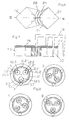
- a horizontal one Cutting device which consists of a cutting ring 23 and a horizontal rotor blade 24 is formed.
- the cutting ring 23 has an inner circumference 25, which essentially corresponds to the inner circumference of the stator 9, is above the Stator cutting elements 1-8 arranged and covers the stator cutting element carrier 1.2-8.2 from.
- the horizontal rotor cutting edge 24 is disc-shaped, covers the rotor cutting element carrier 15 and acts with the cutting ring 23 together, as can be seen from FIG. 5.
- FIG. 6 Another version of the additional, horizontal cutting device is shown in Fig. 6.
- this cutting device consists of plates like that Plate 26, which each cover the stator cutting element carrier 1.1-8.1, and a plate 27 which covers the rotor cutting element carrier 15.
- the plates 26, 27 are provided with sickle-shaped cutting edges 28, 29 which are complementary to one another 7, the effect of this is additional Cutting device shown.
- a long leg of the regrind part 18 is cut, whereupon the cut ground part is cut with the vertical cutting elements can be.
- FIGS. 8A-8D has a stator as in Fig. 1, but are between curved webs 1.2'-3.2 'only three stator cutting elements 1'-3' are evenly distributed, which are attached to stator cutting element carriers 1.1'-3.1 '. Instead of just a rotor, three rotors 12.1-12.3 are provided, the rotor cutting elements Wear 16.1-16.3.
- each rotor 12.1-12.3 is significant smaller than that of the rotor 12 and in terms of the inner circumference of the stator chosen that the rotor cutting element 16.1-16.3 each rotor 12.1-12.3 each Rotor rotation cooperates with the next stator cutting element 2 ', 3', 1 ', as shown in Figures 8B-8D.
- Execution of the cutting mill is a low-dust coarse grinding in the area X (FIG. 8B) and regrind in the area Y (FIG. 8D). To minimize dust formation, it is useful if the Cutting room z. B. is heated by means of a radiator.
Landscapes
- Engineering & Computer Science (AREA)
- Food Science & Technology (AREA)
- Environmental & Geological Engineering (AREA)
- Mechanical Engineering (AREA)
- Crushing And Pulverization Processes (AREA)
- Glass Compositions (AREA)
- Saccharide Compounds (AREA)
- Milling Processes (AREA)
- Processing And Handling Of Plastics And Other Materials For Molding In General (AREA)
Abstract
Description
- Fig. 1
- eine Draufsicht auf eine skizzenhaft dargestellte, erste Ausführung einer Schneidmühle gemäß der Erfindung mit abgenommener Abdeckung,
- Figuren 2A-2F
- verkleinerte Draufsichten auf die Schneidmühle der Fig. 1, die verschiedene Rotorstellungen während einer Rotorumdrehung zeigen,
- Fig. 3
- eine der Fig. 1 ähnliche Draufsicht, die die verschiedenen Stellungen des Rotorschneidelements nach Fig. 2 und das Zerbrechen eines Mahlgutteils zeigt,
- Fig. 4
- eine vergrößerte, perspektivische Ansicht der Schneidmühle nach Fig. 3,
- Fig. 5
- eine der Fig. 4 ähnliche, perspektivische Ansicht mit Darstellung einer zusätzlichen, horizontalen Schneidvorrichtung,
- Fig. 6
- eine Draufsicht auf eine weitere Ausführung der zusätzlichen, horizontalen Schneidvorrichtung,
- Fig. 7
- einen Schnitt längs der Linie VII-VII in Fig. 6 mit Darstellung eines Mahlguts und
- Figuren 8A-8D
- Draufsichten auf eine zweite Ausführung der Schneidmühle gemäß der Erfindung mit mehreren Rotoren und mit Darstellung verschiedener Stellungen der Rotoren während einer Umdrehung der Rotoren.
Claims (13)
- Schneidmühle zum Zerkleinern von Kunststoffteilen, insb. Angüssen von Spritzgußteilen, mit einem Stator, an dessen Innenumfang Statorschneidelemente gleichmäßig verteilt angeordnet sind, und einem im Stator umlaufenden Rotor, auf dessen Umfang mindestens ein Rotorschneidelement angeordnet ist, wobei die Statorschneidelemente mit dem Rotorschneidelement zusammenwirken,
dadurch gekennzeichnet,
daß mindestens ein Rotor (12) im Stator (10) exzentrisch angeordnet ist, einen wesentlich geringeren Umfang (13) als der Statorinnenumfang (9) aufweist und sich mit seiner Achse (14) auf einer Kreisbahn (17) um die Statorachse (11) bewegt. - Schneidmühle nach Anspruch 1,
dadurch gekennzeichnet,
daß der Rotorumfang (13) am Statorinnenumfang (9) abrollt. - Schneidmühle nach Anspruch 2,
dadurch gekennzeichnet,
daß der Rotor (12) mit einer Außenverzahnung und der Stator (10) mit einer Innenverzahnung versehen ist. - Schneidmühle nach einem der Ansprüche 1 bis 3,
dadurch gekennzeichnet,
daß die Anzahl der Statorschneidelemente (1-8) und das Verhältnis des Statorinnenumfangs (9) zum Rotorumfang (13) derart gewählt sind, daß das Rotorschneidelement (16) je Rotorumlauf mit einem (5) der auf das nächste Statorschneidelement (2) gegenüberliegende Statorschneidelement (3-8) zusammenwirkt, wobei alle Statorschneidelemente (1-8) in einer bestimmten Reihenfolge beteiligt werden. - Schneidmühle nach Anspruch 4,
dadurch gekennzeichnet,
daß die Anzahl der Statorschneidelemente (1-8) acht beträgt und das Verhältnis des Statorinnenumfangs (9) zum Rotorumfang (13) derart gewählt ist, daß die Reihenfolge 1, 6, 3, 8, 5, 2, 7, 4 lautet. - Schneidmühle nach einem der Ansprüche 1 bis 3,
dadurch gekennzeichnet,
daß drei Statorschneidelemente (1'-3') und drei Rotoren (12.1-12.3) vorgesehen sind. - Schneidmühle nach Anspruch 6,
dadurch gekennzeichnet,
daß das Verhältnis des Statorinnenumfangs zum Rotorumfang derart gewählt ist, daß das Rotorschneidelement (16.1-16.3) jedes Rotors (12.1-12.3) je Rotorumlauf mit dem nächsten Statorschneidelement (2', 3', 1') zusammenwirkt. - Schneidmühle nach einem der Ansprüche 1 bis 7, die eine Betriebslage mit vertikaler Statorachse aufweist und bei der die Kunststoffteile axial von oben zugeführt werden,
dadurch gekennzeichnet,
daß der Stator (10) eine Innenkammer aufweist, die durch eine der Anzahl der Statorschneidelemente (1-8) entsprechende Anzahl von Stegen (1.2-8.2) begrenzt ist, deren Schmalseiten jeweils einen bestimmten Abstand (a) zu Schmalseiten der benachbarten Stege aufweisen, und daß jedes Statorschneidelement an einem ihm zugeordneten, rahmenförmigen Statorschneidelementträger (z.B. 5.1) befestigt ist, der zwei zu beiden Seiten des Statorschneidelements angeordnete Taschen (19, 20) zur Aufnahme der Stegenden (21, 22) zweier benachbarter Stege (4.1 und 5.1) aufweist. - Schneidmühle nach Anspruch 8,
dadurch gekennzeichnet,
daß der Schneidelementträger (z.B. 5.1) viereckig ausgebildet ist und an einer Ecke das Statorschneidelement (5) aufweist und daß die Taschen (19, 20) in der Nähe des Statorschneidelements (5) angeordnet sind. - Schneidmühle nach Anspruch 8 oder 9,
dadurch gekennzeichnet,
daß oberhalb der Statorschneidelemente (1-8) ein horizontaler Schneidring (23) angeordnet ist, dessen Innenumfang (25) im wesentlichen dem Statorinnenumfang (9) entspricht, und daß auf dem Rotor (12) eine Horizontalrotorschneide (24) angeordnet ist, die mit dem Schneidring (23) zusammenwirkt. - Schneidmühle nach Anspruch 10,
dadurch gekennzeichnet,
daß die Horizontalrotorschneide (24) scheibenförmig ausgebildet ist. - Schneidmühle nach einem der Ansprüche 8 bis 11,
dadurch gekennzeichnet,
daß ein Träger (15) für das Rotorschneidelement (16) vorgesehen ist, der wie der Träger (5.1) des Statorschneidelements (5) ausgebildet ist. - Schneidmühle nach einem der Ansprüche 1 bis 12,
dadurch gekennzeichnet,
daß Mittel zum Erwärmung des Schneidraumes vorgesehen sind.
Applications Claiming Priority (2)
| Application Number | Priority Date | Filing Date | Title |
|---|---|---|---|
| DE19949706 | 1999-10-15 | ||
| DE1999149706 DE19949706A1 (de) | 1999-10-15 | 1999-10-15 | Schneidmühle |
Publications (2)
| Publication Number | Publication Date |
|---|---|
| EP1092476A1 true EP1092476A1 (de) | 2001-04-18 |
| EP1092476B1 EP1092476B1 (de) | 2008-05-21 |
Family
ID=7925740
Family Applications (1)
| Application Number | Title | Priority Date | Filing Date |
|---|---|---|---|
| EP20000122110 Expired - Lifetime EP1092476B1 (de) | 1999-10-15 | 2000-10-12 | Schneidmühle |
Country Status (3)
| Country | Link |
|---|---|
| EP (1) | EP1092476B1 (de) |
| AT (1) | ATE395976T1 (de) |
| DE (2) | DE19949706A1 (de) |
Citations (8)
| Publication number | Priority date | Publication date | Assignee | Title |
|---|---|---|---|---|
| DE2315587B2 (de) | 1972-08-14 | 1975-04-10 | Kobe Steel, Ltd., Kobe (Japan) | Vorrichtung zum Feinmahlen von Gummi |
| DE3201096A1 (de) | 1982-01-15 | 1983-07-28 | Colortronic Reinhard & Co Kg, 6382 Friedrichsdorf | Schneidmuehle zum zerkleinern von anguessen, spritzgussteilen, geblasenen hohlkoerpern und dergleichen |
| DE3444933A1 (de) | 1984-12-08 | 1986-06-12 | Herbold GmbH, Maschinenfabrik, 6922 Meckesheim | Schneidmuehle |
| DE8716200U1 (de) | 1987-04-01 | 1988-07-28 | Rößler, Kurt, 4550 Bramsche | Zerkleinerungsvorrichtung |
| DE9200997U1 (de) | 1992-01-29 | 1992-04-09 | F. Kurt Retsch GmbH & Co KG, 5657 Haan | Rotoranordnung für eine Schneidmühle |
| GB2268097A (en) * | 1992-06-19 | 1994-01-05 | Yang Mu Tsang | Crushing machine. |
| WO1997038793A1 (en) * | 1996-04-15 | 1997-10-23 | Kent Vedefors | Device for disintegrating |
| WO1999043480A1 (en) * | 1998-02-27 | 1999-09-02 | Maguire Products, Inc. | Radial granulator and method |
-
1999
- 1999-10-15 DE DE1999149706 patent/DE19949706A1/de not_active Withdrawn
-
2000
- 2000-10-12 AT AT00122110T patent/ATE395976T1/de not_active IP Right Cessation
- 2000-10-12 EP EP20000122110 patent/EP1092476B1/de not_active Expired - Lifetime
- 2000-10-12 DE DE50015168T patent/DE50015168D1/de not_active Expired - Fee Related
Patent Citations (8)
| Publication number | Priority date | Publication date | Assignee | Title |
|---|---|---|---|---|
| DE2315587B2 (de) | 1972-08-14 | 1975-04-10 | Kobe Steel, Ltd., Kobe (Japan) | Vorrichtung zum Feinmahlen von Gummi |
| DE3201096A1 (de) | 1982-01-15 | 1983-07-28 | Colortronic Reinhard & Co Kg, 6382 Friedrichsdorf | Schneidmuehle zum zerkleinern von anguessen, spritzgussteilen, geblasenen hohlkoerpern und dergleichen |
| DE3444933A1 (de) | 1984-12-08 | 1986-06-12 | Herbold GmbH, Maschinenfabrik, 6922 Meckesheim | Schneidmuehle |
| DE8716200U1 (de) | 1987-04-01 | 1988-07-28 | Rößler, Kurt, 4550 Bramsche | Zerkleinerungsvorrichtung |
| DE9200997U1 (de) | 1992-01-29 | 1992-04-09 | F. Kurt Retsch GmbH & Co KG, 5657 Haan | Rotoranordnung für eine Schneidmühle |
| GB2268097A (en) * | 1992-06-19 | 1994-01-05 | Yang Mu Tsang | Crushing machine. |
| WO1997038793A1 (en) * | 1996-04-15 | 1997-10-23 | Kent Vedefors | Device for disintegrating |
| WO1999043480A1 (en) * | 1998-02-27 | 1999-09-02 | Maguire Products, Inc. | Radial granulator and method |
Also Published As
| Publication number | Publication date |
|---|---|
| DE50015168D1 (de) | 2008-07-03 |
| DE19949706A1 (de) | 2001-04-19 |
| EP1092476B1 (de) | 2008-05-21 |
| ATE395976T1 (de) | 2008-06-15 |
Similar Documents
| Publication | Publication Date | Title |
|---|---|---|
| EP0064596B1 (de) | Schneidmühle zum Zerkleinern von Angüssen, Spritzgussteilen, geblasenen Hohlkörpern ud. dgl. | |
| EP2987557B1 (de) | Zerkleinerungsmaschine zur zerkleinerung eines produkts | |
| EP0346661A2 (de) | Häcksel- und Schnitzelmaschine | |
| DE2256267C3 (de) | Mit Scherwirkung arbeitender Zerkleinerer | |
| EP1237656A1 (de) | Vorrichtung zum zerkleinern eines zerkleinerungsgutes | |
| EP0124138B1 (de) | Verfahren und Vorrichtung zur Zerkleinerung von Pflanzengut | |
| EP1899072B1 (de) | Zerkleinerungsvorrichtung | |
| EP0387868A2 (de) | Vorrichtung zum Zerkleinern von Rest- und Abfallhölzern | |
| DE2502665A1 (de) | Abfallzerkleinerungsvorrichtung | |
| DE4239342A1 (de) | Zerkleinerungsmaschine zum Mahlen oder Häckseln von industriellen und landwirtschaftlichen Produkten und Abfällen | |
| DE2357765A1 (de) | Vorrichtung zur zerkleinerung von abfallstoffen | |
| EP1092476B1 (de) | Schneidmühle | |
| DE4342647C2 (de) | Zerkleinerungsvorrichtung | |
| DE3201096C2 (de) | Schneidmühle zum Zerkleinern von Angüssen | |
| DE3908395C2 (de) | Vorrichtung zum Zerkleinern von Rest- und Abfallhölzern | |
| DE3313517A1 (de) | Granulator | |
| DD256041A3 (de) | Zerkleinerungsmaschine fuer thermoplastabfaelle | |
| DE19606746C1 (de) | Trichterhacker zum Zerkleinern von insbesondere Holz | |
| DE4213608A1 (de) | Verfahren und vorrichtung zum zerkleinern von gummibrocken | |
| DE10113953C1 (de) | Vorrichtung zum Zerkleinern von Kunststoffgebilden mit geringer Materialstärke | |
| EP0302131B1 (de) | Mühle | |
| DE2542908A1 (de) | Vorrichtung zum zerkleinern von altmaterial | |
| EP2548648B1 (de) | Mühle zur Zerkleinerung von Mahlgut | |
| EP0420000B1 (de) | Schneidsatz für eine Zerkleinerungsmaschine | |
| EP0401573A2 (de) | Vorrichtung zur Zerkleinerung von Kunststoffteilen |
Legal Events
| Date | Code | Title | Description |
|---|---|---|---|
| PUAI | Public reference made under article 153(3) epc to a published international application that has entered the european phase |
Free format text: ORIGINAL CODE: 0009012 |
|
| AK | Designated contracting states |
Kind code of ref document: A1 Designated state(s): AT BE CH CY DE DK ES FI FR GB GR IE IT LI LU MC NL PT SE |
|
| AX | Request for extension of the european patent |
Free format text: AL;LT;LV;MK;RO;SI |
|
| 17P | Request for examination filed |
Effective date: 20011018 |
|
| AKX | Designation fees paid |
Free format text: AT BE CH CY DE DK ES FI FR GB GR IE IT LI LU MC NL PT SE |
|
| 17Q | First examination report despatched |
Effective date: 20061222 |
|
| GRAP | Despatch of communication of intention to grant a patent |
Free format text: ORIGINAL CODE: EPIDOSNIGR1 |
|
| RIC1 | Information provided on ipc code assigned before grant |
Ipc: B02C 18/08 20060101ALI20071203BHEP Ipc: B02C 18/00 20060101AFI20071203BHEP Ipc: B29B 17/00 20060101ALI20071203BHEP |
|
| GRAS | Grant fee paid |
Free format text: ORIGINAL CODE: EPIDOSNIGR3 |
|
| GRAA | (expected) grant |
Free format text: ORIGINAL CODE: 0009210 |
|
| AK | Designated contracting states |
Kind code of ref document: B1 Designated state(s): AT BE CH CY DE DK ES FI FR GB GR IE IT LI LU MC NL PT SE |
|
| REG | Reference to a national code |
Ref country code: GB Ref legal event code: FG4D Free format text: NOT ENGLISH |
|
| REG | Reference to a national code |
Ref country code: CH Ref legal event code: EP |
|
| REF | Corresponds to: |
Ref document number: 50015168 Country of ref document: DE Date of ref document: 20080703 Kind code of ref document: P |
|
| REG | Reference to a national code |
Ref country code: IE Ref legal event code: FG4D Free format text: LANGUAGE OF EP DOCUMENT: GERMAN |
|
| PG25 | Lapsed in a contracting state [announced via postgrant information from national office to epo] |
Ref country code: ES Free format text: LAPSE BECAUSE OF FAILURE TO SUBMIT A TRANSLATION OF THE DESCRIPTION OR TO PAY THE FEE WITHIN THE PRESCRIBED TIME-LIMIT Effective date: 20080901 Ref country code: FI Free format text: LAPSE BECAUSE OF FAILURE TO SUBMIT A TRANSLATION OF THE DESCRIPTION OR TO PAY THE FEE WITHIN THE PRESCRIBED TIME-LIMIT Effective date: 20080521 |
|
| NLV1 | Nl: lapsed or annulled due to failure to fulfill the requirements of art. 29p and 29m of the patents act | ||
| PG25 | Lapsed in a contracting state [announced via postgrant information from national office to epo] |
Ref country code: NL Free format text: LAPSE BECAUSE OF FAILURE TO SUBMIT A TRANSLATION OF THE DESCRIPTION OR TO PAY THE FEE WITHIN THE PRESCRIBED TIME-LIMIT Effective date: 20080521 |
|
| REG | Reference to a national code |
Ref country code: IE Ref legal event code: FD4D |
|
| PG25 | Lapsed in a contracting state [announced via postgrant information from national office to epo] |
Ref country code: PT Free format text: LAPSE BECAUSE OF FAILURE TO SUBMIT A TRANSLATION OF THE DESCRIPTION OR TO PAY THE FEE WITHIN THE PRESCRIBED TIME-LIMIT Effective date: 20081021 Ref country code: IE Free format text: LAPSE BECAUSE OF FAILURE TO SUBMIT A TRANSLATION OF THE DESCRIPTION OR TO PAY THE FEE WITHIN THE PRESCRIBED TIME-LIMIT Effective date: 20080521 Ref country code: DK Free format text: LAPSE BECAUSE OF FAILURE TO SUBMIT A TRANSLATION OF THE DESCRIPTION OR TO PAY THE FEE WITHIN THE PRESCRIBED TIME-LIMIT Effective date: 20080521 Ref country code: SE Free format text: LAPSE BECAUSE OF FAILURE TO SUBMIT A TRANSLATION OF THE DESCRIPTION OR TO PAY THE FEE WITHIN THE PRESCRIBED TIME-LIMIT Effective date: 20080821 |
|
| PLBE | No opposition filed within time limit |
Free format text: ORIGINAL CODE: 0009261 |
|
| STAA | Information on the status of an ep patent application or granted ep patent |
Free format text: STATUS: NO OPPOSITION FILED WITHIN TIME LIMIT |
|
| 26N | No opposition filed |
Effective date: 20090224 |
|
| BERE | Be: lapsed |
Owner name: HOFFMANN, RALF Effective date: 20081031 |
|
| PG25 | Lapsed in a contracting state [announced via postgrant information from national office to epo] |
Ref country code: MC Free format text: LAPSE BECAUSE OF NON-PAYMENT OF DUE FEES Effective date: 20081031 |
|
| REG | Reference to a national code |
Ref country code: CH Ref legal event code: PL |
|
| GBPC | Gb: european patent ceased through non-payment of renewal fee |
Effective date: 20081012 |
|
| REG | Reference to a national code |
Ref country code: FR Ref legal event code: ST Effective date: 20090630 |
|
| PG25 | Lapsed in a contracting state [announced via postgrant information from national office to epo] |
Ref country code: DE Free format text: LAPSE BECAUSE OF NON-PAYMENT OF DUE FEES Effective date: 20090501 Ref country code: IT Free format text: LAPSE BECAUSE OF FAILURE TO SUBMIT A TRANSLATION OF THE DESCRIPTION OR TO PAY THE FEE WITHIN THE PRESCRIBED TIME-LIMIT Effective date: 20080521 |
|
| PG25 | Lapsed in a contracting state [announced via postgrant information from national office to epo] |
Ref country code: BE Free format text: LAPSE BECAUSE OF NON-PAYMENT OF DUE FEES Effective date: 20081031 |
|
| PG25 | Lapsed in a contracting state [announced via postgrant information from national office to epo] |
Ref country code: FR Free format text: LAPSE BECAUSE OF NON-PAYMENT OF DUE FEES Effective date: 20081031 Ref country code: CH Free format text: LAPSE BECAUSE OF NON-PAYMENT OF DUE FEES Effective date: 20081031 Ref country code: LI Free format text: LAPSE BECAUSE OF NON-PAYMENT OF DUE FEES Effective date: 20081031 |
|
| PG25 | Lapsed in a contracting state [announced via postgrant information from national office to epo] |
Ref country code: GB Free format text: LAPSE BECAUSE OF NON-PAYMENT OF DUE FEES Effective date: 20081012 |
|
| PG25 | Lapsed in a contracting state [announced via postgrant information from national office to epo] |
Ref country code: AT Free format text: LAPSE BECAUSE OF NON-PAYMENT OF DUE FEES Effective date: 20081012 |
|
| PG25 | Lapsed in a contracting state [announced via postgrant information from national office to epo] |
Ref country code: LU Free format text: LAPSE BECAUSE OF NON-PAYMENT OF DUE FEES Effective date: 20081012 |
|
| PG25 | Lapsed in a contracting state [announced via postgrant information from national office to epo] |
Ref country code: CY Free format text: LAPSE BECAUSE OF FAILURE TO SUBMIT A TRANSLATION OF THE DESCRIPTION OR TO PAY THE FEE WITHIN THE PRESCRIBED TIME-LIMIT Effective date: 20080521 |
|
| PG25 | Lapsed in a contracting state [announced via postgrant information from national office to epo] |
Ref country code: GR Free format text: LAPSE BECAUSE OF FAILURE TO SUBMIT A TRANSLATION OF THE DESCRIPTION OR TO PAY THE FEE WITHIN THE PRESCRIBED TIME-LIMIT Effective date: 20080822 |