EP1092989A1 - Inductive sensor head for metal detectors - Google Patents
Inductive sensor head for metal detectors Download PDFInfo
- Publication number
- EP1092989A1 EP1092989A1 EP99308054A EP99308054A EP1092989A1 EP 1092989 A1 EP1092989 A1 EP 1092989A1 EP 99308054 A EP99308054 A EP 99308054A EP 99308054 A EP99308054 A EP 99308054A EP 1092989 A1 EP1092989 A1 EP 1092989A1
- Authority
- EP
- European Patent Office
- Prior art keywords
- coils
- field
- field coil
- sense coils
- sense
- Prior art date
- Legal status (The legal status is an assumption and is not a legal conclusion. Google has not performed a legal analysis and makes no representation as to the accuracy of the status listed.)
- Granted
Links
- 230000001939 inductive effect Effects 0.000 title claims abstract description 13
- 239000002184 metal Substances 0.000 title description 8
- 229910052751 metal Inorganic materials 0.000 title description 8
- 230000004907 flux Effects 0.000 claims abstract description 27
- CWYNVVGOOAEACU-UHFFFAOYSA-N Fe2+ Chemical compound [Fe+2] CWYNVVGOOAEACU-UHFFFAOYSA-N 0.000 claims abstract description 18
- 238000004804 winding Methods 0.000 claims description 45
- 230000008878 coupling Effects 0.000 claims description 12
- 238000010168 coupling process Methods 0.000 claims description 12
- 238000005859 coupling reaction Methods 0.000 claims description 12
- 230000005284 excitation Effects 0.000 claims description 3
- 230000004323 axial length Effects 0.000 abstract description 2
- 239000011449 brick Substances 0.000 abstract description 2
- 239000004567 concrete Substances 0.000 abstract description 2
- 238000010586 diagram Methods 0.000 description 6
- 238000005259 measurement Methods 0.000 description 6
- 230000006872 improvement Effects 0.000 description 4
- 230000035699 permeability Effects 0.000 description 3
- 230000006698 induction Effects 0.000 description 2
- 239000000463 material Substances 0.000 description 2
- 238000000034 method Methods 0.000 description 2
- 230000003321 amplification Effects 0.000 description 1
- 230000000712 assembly Effects 0.000 description 1
- 238000000429 assembly Methods 0.000 description 1
- 230000008901 benefit Effects 0.000 description 1
- 239000004020 conductor Substances 0.000 description 1
- 230000001419 dependent effect Effects 0.000 description 1
- 238000001514 detection method Methods 0.000 description 1
- 230000000694 effects Effects 0.000 description 1
- 238000003199 nucleic acid amplification method Methods 0.000 description 1
- 239000011505 plaster Substances 0.000 description 1
- 230000008569 process Effects 0.000 description 1
- 238000010408 sweeping Methods 0.000 description 1
Images



Classifications
-
- G—PHYSICS
- G01—MEASURING; TESTING
- G01V—GEOPHYSICS; GRAVITATIONAL MEASUREMENTS; DETECTING MASSES OR OBJECTS; TAGS
- G01V3/00—Electric or magnetic prospecting or detecting; Measuring magnetic field characteristics of the earth, e.g. declination, deviation
- G01V3/08—Electric or magnetic prospecting or detecting; Measuring magnetic field characteristics of the earth, e.g. declination, deviation operating with magnetic or electric fields produced or modified by objects or geological structures or by detecting devices
- G01V3/10—Electric or magnetic prospecting or detecting; Measuring magnetic field characteristics of the earth, e.g. declination, deviation operating with magnetic or electric fields produced or modified by objects or geological structures or by detecting devices using induction coils
- G01V3/104—Electric or magnetic prospecting or detecting; Measuring magnetic field characteristics of the earth, e.g. declination, deviation operating with magnetic or electric fields produced or modified by objects or geological structures or by detecting devices using induction coils using several coupled or uncoupled coils
- G01V3/108—Electric or magnetic prospecting or detecting; Measuring magnetic field characteristics of the earth, e.g. declination, deviation operating with magnetic or electric fields produced or modified by objects or geological structures or by detecting devices using induction coils using several coupled or uncoupled coils the emitter and the receiver coils or loops being uncoupled by positioning them perpendicularly to each other
Definitions
- the invention relates to an inductive sensor head for detecting of a ferrous, ferric and/or non-ferrous electrically conducting objects buried in a surrounding medium.
- the field coil is for generating an alternating magnetic field while the other coil, the sense coil, measures changes caused by a ferrous or non-ferrous material coming into the magnetic flux field while moving the detector over the medium containing the hidden disturbing object.
- a problem with the known metal detectors is on the one hand the relatively large size which is unavoidable due to the side-by-side arrangement of the field coil and the sensor coil and on the other hand that the detector must be swept over a certain search area in a kind of scanning process.
- An inductive sensor head for detecting of ferrous or non-ferrous electrically conducting objects hidden in a medium is defined by the features of claim 1.
- Such a sensor head comprises at least one larger diameter field coil with a small axial length-to-diameter-ratio and at least one twin pair of coaxially arranged sense coils both having a small diameter compared to the diameter of the field coil.
- the inductance of the or each sense coil is significantly higher than the inductance of the field coil. The higher the inductance the more sensitive the sense coil is to magnetic changes and the less gain is needed in the following amplifiers.
- the common axis of said twin pair of sense coils is extending perpendicular to the axis and in a diameter direction of the field coil, and said axis is positioned in a plane of the winding plane of said field coil or in a plane essentially parallel to the winding plane of that field coil. Further, the said two sense coils are positioned in an equal distance from the center of the field coil such that they are penetrated by the same magnetic flux direction of the flux field emanating from the field coil when excitated by an electric current.
- a significant improvement of the concept of the invention is achieved if a twin pair of coaxially positioned field coils is provided.
- the mutual axial distance of said two field coils can be rather close and may preferably be less than their internal diameter.
- the distance between the field coils is arranged such that the difference in magnetic field strength on a rebar is sufficiently large that it can be accurately measured.
- two twin pairs of sense coils with orthogonally arranged axes are positioned in a center plane parallel and approximately at half-way distance between the winding planes of said two field coils.
- the invention also provides an advantageous driving circuit for the said combination of a twin pair of field coils and a double twin-set of sense coils as defined in claim 3, wherein additional correction coils are provided in series connection with each of said two field coils in order to minimize magnetic offsets due to the fact that the sense coils cannot be or are difficult to exactly be positioned in the magnetic null position of both field coils.
- the basic magnetic configuration for an induction sensor head is shown in Fig. 1 and comprises a relatively large diameter field coil F with few turns of wire and an outer diameter of typically in the range of 40 to 80 mm and preferably between 60 and 70 mm.
- the term "few turns of wire” will be explained below.
- An AC current is passed to the field coil F to generate a magentic field as visualized in Fig. 2 by flux lines FL in free space.
- the magnetic flux field is measured using a twin pair of small diameter sense coils A, B having many turns of wire compared to the wire turn number of the field coil F.
- the twin pair of sense coils A and B is arranged on a common axis X-X which is oriented perpendicular to the central axis of the field coil F and extending through the diameter thereof. Accordingly, as shown in the lower side view presentation of Fig. 1, the sense coils A, B are arranged within the free space of the field coil F. As can be also seen from Fig. 1, the field coil F is of small axial length compared to its diameter. If no disturbance exists, the magnetic flux vector is parallel to the axis of the field coil F in the interior space encompassed by the field coil F.
- sense coils A and B are configured such that their common axis is perpendicular to the axis of the field coil F there will be no component of magnetic flux that is coaxial with said sense coils A and B, and hence no voltage will be induced in them.
- a metal object 1 (ferrous or non-ferrous), e. g., a rebar is brought or comes into the proximity with the field coil F as shown in Fig. 3, the magnetic field is distorted resulting in a component of the magnetic flux vector being coaxial with the sense coils A, B and hence inducing a voltage in the sense coils A, B.
- the magnitude of the voltage induced is a function of the size, composition and position of the disturbing metal object 1.
- Non-ferrous conductive objects e. g. copper
- Eddy currents will also be induced in ferrous conductors such as rebars, however, it is believed that the effects due to permeability dominate.
- the output voltage from each of the sense coils A, B will be similar to the diagram of Fig. 4.
- the graph is the magnitude of the voltage from the sense coil as a rebar is swept over it.
- the Y axis is the magnitude of the voltage V and it has arbitrary units as it will vary with many geometric factors.
- the X axis is the sample number for the measurement and in this instance was 5 samples per mm movement.
- the output voltage will be zero when the object 1 is directly over the center of the sense coil(s). From each sense coil we get an S curve shape as shown in Fig. 4. It is evident that the "S" curves for each of the sense coils A, B are displaced by the physical distance between the center line, i. e. the common axis of the sense coils A, B.
- the two field coils F 1 , F 2 are essentially identical and are therefore called a twin pair of field coils.
- the second or bottom field coil F 2 is coaxially arranged with the first or top field coil F 1 but axially displaced by a certain distance which usually is smaller than the inner diameter of the field coils F 1 , F 2 .
- This twin-set arrangement of two field coils F 1 and F 2 enables a second measurement that allows the depth of a disturbing object to be resolved.
- a certain disadvantage of this configuration arises from the fact that the sense coils A, B cannot be arranged in the magnetic null position of both field coils F 1 , F 2 .
- Fig. 5 shows that the magnetic flux lines produced, e. g., by the first or top field coil F 1 are curved as they pass through the sense coils A, B, and hence there is a component of the magnetic flux vector coaxial with the sense coils A, B. This induces a voltage in the sense coils without the influence of a disturbing object 1, e. g. a rebar.
- the depth of an object 1 can be resolved by taking the ratio of the two received signals strenghts, one from each of the field coils F 1 , F 2 .
- a further significant improvement is achieved by an implementation using a twin pair of two field coils F 1 , F 2 and two orthogonal twin pairs of sense coils A, B and C, D, respectively, as shown in Fig. 6.
- the orthogonal pairs of sense coils A, B and C, D, respectively allow the detection of, e. g., a rebar at an arbitrary angle position.
- the signal processing uses the vector sum of the signals produced by the two pairs of sense coils.
- the outer diameter of the field coil twin pair F 1 , F 2 may be in the range of 40 to 80 mm preferably between 60 and 70 mm, whereas the inner diameter of the field coils may be in the range of 30 to 70 preferably in the range of 45 to 55 mm.
- the axial distance of the two field coils F 1 and F 2 may be between 10 and 50 mm, preferably in the range of 15 to 40 mm and typically about 30 mm.
- the winding depth and height of the field coils F 1 , F 2 is typically about 4 to 10 mm and preferably about 7 mm.
- a winding number of typically 50 to 250 turns and preferable 100 turns are to be understood resulting in an inductance value of about 1.5mH for a wire cross section of typically 0.5 mm.
- the DC resistance of such a field coil is typically in the range of 2 ⁇ .
- the respective parameters are for the term "many turns of wire” used for the sense winding of about 2000 to 6000 turns, preferably about 4000 turns resulting for a wire diameter of 0.06 mm in an inductance value of 100mH.
- the DC resistance of such a sense coil is in the range of 800 ⁇ , and the non-neglectable self-capacitance is about 20pF.
- the outer diameter of the sense coils is typically about 15 mm.
- a rectangular AC drive voltage is applied time sequentially to each of the field coils F 1 and F 2 .
- the driving current is not a linear ramp.
- the voltages induced in the sense coils are not rectangular. Rather, the induced voltages are a function of the L/R time constants of the field coils F 1 , F 2 .
- the induced offset voltage resulting from the sense coils A, B and/or C, D not being arranged in the magnetic null position of the field coils F 1 , F 2 limits the possible pre-amplifier gain.
- at least one correction winding 3 can be and should be added to the sense coils A, B, C and D, respectively.
- a fraction of the current excitating the field coils F 1 , F 2 passes through each of such correction windings 3, such that the magnetic field generated by each of the correction windings cancels with that generated by the respective field coil in the vicinity of the sense coils.
- each of the sense coils is provided with a trim winding 2 so that each sense coil can be individually adjusted to a precise magnetic null position during calibration of the inductive sensor head.
- the correction winding(s) 3 and the trim winding 2 are only shown for sense coil A.
- each of the sense coils A, B, C and D is provided with an identical correction winding(s) and trim winding, respectively, as shown in Fig. 9.
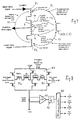
- the magnetic diagram of Fig. 7 shows the various magnetic couplings between the field coils F 1 , F 2 and the four sense coils A, B, C, D.
- a magnetic coupling 10 between the upper, first field coil F 1 and the second, bottom field coil F 2 , further an electromagnetic coupling 12 and 13, respectively, between the first and the second field coil F 1 , F 2 and the sense coils A, B, C, D, which depends on the presence or absence of a disturbing object 1, e. g. a rebar, respectively, a still further coupling 14, 16 between the correction winding(s) 3 and each of the sense coils A, B, C, D as well as another coupling 15 between the sections of the correction winding(s) 3.
- This current produces magnetic flux in each coil.
- the phase and coupling between the correction winding 3 and the sense coils A, B, C, D is such that the component of flux coaxial with the respective sense coil due to the field coil is cancelled in the vicinity of the respective sense coil.
- the diagram of Fig. 7 only shows one correction winding 3 and one sense coil, e. g. sense coil A. In reality, however, and for the case of four sense coils, there will be four correction windings in series, one coupling to each associated sense coil as depicted in the schematic electric circuit diagram of Fig. 9.
- the first one of an inductively coupled pair of correction windings 3 from each of the four sense coil assemblies A, B, C and D, respectively, and one of the two field coils F 1 or F 2 , respectively, are connected in series.
- the inductively coupled second part of the correction winding 3 from each of the four sense coils and the respective other field coil F 2 or F 1 are again connected in series.
- the phase of the correction windings 3 is set so that the sum of the fluxes from the correction winding 3 and the associated field coil approximately cancels in the vicinity of the sense coil. As there is no net flux coaxial with the sense coils no voltage is induced.
- a disturbing object 1 i. e.
- a rebar is located in the vicinity of the field coils, the couplings 12 and 13 (Fig. 7) between the field coils F 1 , F 2 and the respective sense coil is altered resulting in there being a net component of flux coaxial with the respective sense coil. As there is a net flux coaxial with each of the sense coils, a respective voltage is induced. A subsequent excitation of the bottom, second field coil F2 by a current results in similar observations.
- a further adjustment may be provided by the addition of an extra trim winding 2 on each of the sense coils A, B, C and D, respectively.
- a small adjustable fraction of the field coil current is passed in each of the trim winding 2 and its magnitude is controlled by a microcontroller 40 (Fig. 8). By changing the magnitude of the trim current by the microcontroller 40 the ratio of the flux from the respective field coil and the sum of the fluxes from the correction windings 3 and trim windings 2 cancel in the vicinity of each of the sense coils.
- FIG. 8 and 9 show the main components of a field coil driver bridge 41 and sense amplifier 42 followed by a multiplexed A/D- converter 30 as a signal input source for microcontroller 40.
- a display and further user buttons are not shown in the drawings of Figs. 8 and 9.
- the two field coils F 1 , F 2 in electrical series connection with the associated correction winding(s) 2 are driven by a 4-FET switching bridge. As only one of the field coils is driven at a time part, the switching bridge may share common components to save cost.
- the center arm of the bridge 41 is common to both field coils F 1 , F 2 and is always driven by the microcontroller 40.
- the right or left arms of the bridge are driven by the microcontroller 40.
- each of the four sense coils A, B, C, D there is a sense amplifier 42 having a gain of approximately 50 times.
- the outputs of the sense amplifiers 42 are supplied to plural input-port A/D-converter 30 which is multiplexed to time-sequentially read the outputs of the four sense amplifiers 42.
- the depth of a disturbing object 1, i. e. a rebar may be determined by the use of a prestored knowledge base.
- the knowledge base is the result of measuring many rebars of different diameters at coverage depths from for example 10 mm to 100 mm. To determine the cover or depth of a rebar the following process steps are performed:
- Fig. 10 shows an overall-view for the arrangement and implementation of an inductive sensor head according to the invention with the significant advantage that a hidden object 1 can be located in a horizontal plane but also with respect to its approximate depth within a certain cover range.
- the microcontroller 40 receives the sense coils measuring values via the multiplexed A/D-converter 30. During a pre-measurement calibration step, the digitally controlled trim currents for the trim windings 2 are adjusted to optimize the coupling of the correction winding(s) 3.
- the microcontroller 40 also initiates and controls the field coils drive electronics as for example shown in Fig. 8. For the purpose of clarity, in Fig. 10 only one twin pair of sense coils A, B is shown.
Landscapes
- Life Sciences & Earth Sciences (AREA)
- Engineering & Computer Science (AREA)
- Physics & Mathematics (AREA)
- Remote Sensing (AREA)
- Geology (AREA)
- Environmental & Geological Engineering (AREA)
- Electromagnetism (AREA)
- General Life Sciences & Earth Sciences (AREA)
- General Physics & Mathematics (AREA)
- Geophysics (AREA)
- Geophysics And Detection Of Objects (AREA)
- Investigating Or Analyzing Materials By The Use Of Magnetic Means (AREA)
- Measurement Of Length, Angles, Or The Like Using Electric Or Magnetic Means (AREA)
Abstract
Description
- The invention relates to an inductive sensor head for detecting of a ferrous, ferric and/or non-ferrous electrically conducting objects buried in a surrounding medium.
- Metal detectors for detecting ferrous or eventually non-ferrous objects in media like walls of concrete, brick, plaster or the like or in ground based on the disturbance or modulation of the inductive coupling between two coils are known in the art. US 5,729,143 describes a microprocessor controlled metal detector which uses in combination a transmitter coil providing a periodically varying magnetic field and a receiver coil connected thereto in an inductive bridge. The detector comprises means for balancing the two overlappingly arranged coils automatically and electronically for compensating of any initial coil misalignments or unwanted signals, in particular during an initial calibration step. In the known metal detector one of the coils, the field coil, is for generating an alternating magnetic field while the other coil, the sense coil, measures changes caused by a ferrous or non-ferrous material coming into the magnetic flux field while moving the detector over the medium containing the hidden disturbing object.
- A problem with the known metal detectors is on the one hand the relatively large size which is unavoidable due to the side-by-side arrangement of the field coil and the sensor coil and on the other hand that the detector must be swept over a certain search area in a kind of scanning process.
- It is an object of the invention to provide an inductive sensor head which is small in size and may be used as a hand-held tool or may be integrated into an electric, preferably hand-held tool like a drill hammer.
- It is a further object of the invention to provide an inductive sensor head which provides sufficient clear information about a hidden ferrous or non-ferrous electrically conducting object without the necessity of sweeping the sensor head over a certain working area of the medium in which said object may be buried.
- An inductive sensor head for detecting of ferrous or non-ferrous electrically conducting objects hidden in a medium is defined by the features of
claim 1. Such a sensor head comprises at least one larger diameter field coil with a small axial length-to-diameter-ratio and at least one twin pair of coaxially arranged sense coils both having a small diameter compared to the diameter of the field coil. Preferably, the inductance of the or each sense coil is significantly higher than the inductance of the field coil. The higher the inductance the more sensitive the sense coil is to magnetic changes and the less gain is needed in the following amplifiers. The common axis of said twin pair of sense coils is extending perpendicular to the axis and in a diameter direction of the field coil, and said axis is positioned in a plane of the winding plane of said field coil or in a plane essentially parallel to the winding plane of that field coil. Further, the said two sense coils are positioned in an equal distance from the center of the field coil such that they are penetrated by the same magnetic flux direction of the flux field emanating from the field coil when excitated by an electric current. - Advantageous improvements and embodiments of the invention as defined in
claim 1 are the subject-matters of further dependent claims. - For achieving better positional information, in particular for resolving depth information in relation to a hidden object, e. g., a reenforcing bar ("rebar" in the following) from a single position measurement cycle, a significant improvement of the concept of the invention is achieved if a twin pair of coaxially positioned field coils is provided. The mutual axial distance of said two field coils can be rather close and may preferably be less than their internal diameter. As a rule, the distance between the field coils is arranged such that the difference in magnetic field strength on a rebar is sufficiently large that it can be accurately measured. In addition, two twin pairs of sense coils with orthogonally arranged axes are positioned in a center plane parallel and approximately at half-way distance between the winding planes of said two field coils.
- As will be described in the following in further details, the invention also provides an advantageous driving circuit for the said combination of a twin pair of field coils and a double twin-set of sense coils as defined in
claim 3, wherein additional correction coils are provided in series connection with each of said two field coils in order to minimize magnetic offsets due to the fact that the sense coils cannot be or are difficult to exactly be positioned in the magnetic null position of both field coils. - The invention and advantageous details and embodiments thereof will be described in the following with reference to the accompanying drawings in which:
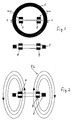
- Fig. 1 depicts a basic arrangement of a field coil and a twin-set of sense coils in accordance with the invention;
- Fig. 2 visualizes the magnetic flux in free space if an excitation current is passing through the field coil;
- Fig. 3 visualizes how the magnetic field is distorted if a metal object is coming into the proximity of the magnetic field emanating from the field coil;
- Fig. 4 is a diagram of the output voltage from each of the two sense coils in Fig. 1 if an object of a certain permeability (e. g. a rebar) is swept across the field and sensor coils arrangement of Fig. 2;
- Fig. 5 depicts the basic concept of a coil configuration with two identical axially displaced field coils for achieving positional and depth information;
- Fig. 6 shows the implementation concept of two field coils as shown in Fig. 5 and two orthogonally arranged twin pairs of sense coils for detecting of a hidden object at an arbitrary angle position within a medium;
- Fig. 7 visualizes the basic principle of a magnetic arrangement of the two field coils both additionally equipped with correction windings and trim windings as an adjustment means for magnetic flux correction;
- Fig. 8 shows the circuit arrangement of a switching bridge for time sequential driving of a twin pair of field coils additionally provided with correction windings;
- Fig. 9 shows a circuit configuration example of an amplification and multiplexing A/D-converting circuit for the output signal from the two twin pairs of sense coils of Fig. 6; and
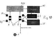
- Fig. 10 shows the basic structure of a complete control and read out system of an inductive sensor head according to the invention.
-
- Throughout the various figures of the drawings the same reference signs are used for identical or corresponding parts.
- The basic magnetic configuration for an induction sensor head according to the invention is shown in Fig. 1 and comprises a relatively large diameter field coil F with few turns of wire and an outer diameter of typically in the range of 40 to 80 mm and preferably between 60 and 70 mm. The term "few turns of wire" will be explained below. An AC current is passed to the field coil F to generate a magentic field as visualized in Fig. 2 by flux lines FL in free space. The magnetic flux field is measured using a twin pair of small diameter sense coils A, B having many turns of wire compared to the wire turn number of the field coil F. As shown by the schematic top and side views of Fig. 1, the twin pair of sense coils A and B is arranged on a common axis X-X which is oriented perpendicular to the central axis of the field coil F and extending through the diameter thereof. Accordingly, as shown in the lower side view presentation of Fig. 1, the sense coils A, B are arranged within the free space of the field coil F. As can be also seen from Fig. 1, the field coil F is of small axial length compared to its diameter. If no disturbance exists, the magnetic flux vector is parallel to the axis of the field coil F in the interior space encompassed by the field coil F. As the sense coils A and B are configured such that their common axis is perpendicular to the axis of the field coil F there will be no component of magnetic flux that is coaxial with said sense coils A and B, and hence no voltage will be induced in them.
- If a metal object 1 (ferrous or non-ferrous), e. g., a rebar is brought or comes into the proximity with the field coil F as shown in Fig. 3, the magnetic field is distorted resulting in a component of the magnetic flux vector being coaxial with the sense coils A, B and hence inducing a voltage in the sense coils A, B. The magnitude of the voltage induced is a function of the size, composition and position of the
disturbing metal object 1. - Bringing an
object 1 with permeability (e. g. a ferrous rebar) into the magnetic field will cause a local increase in magnetic flux density which can be considered to twist the flux lines resulting in an induced voltage in the sense coils A, B. Non-ferrous conductive objects (e. g. copper) also disturb the magnetic flux field. This is believed to be due to induced eddy currents. Eddy currents will also be induced in ferrous conductors such as rebars, however, it is believed that the effects due to permeability dominate. - If the rebar, i. e. the
object 1 is swept across the assembly in Fig. 3 from right to left, the output voltage from each of the sense coils A, B will be similar to the diagram of Fig. 4. The graph is the magnitude of the voltage from the sense coil as a rebar is swept over it. The Y axis is the magnitude of the voltage V and it has arbitrary units as it will vary with many geometric factors. The X axis is the sample number for the measurement and in this instance was 5 samples per mm movement. - For each sense coil A, B, the output voltage will be zero when the
object 1 is directly over the center of the sense coil(s). From each sense coil we get an S curve shape as shown in Fig. 4. It is evident that the "S" curves for each of the sense coils A, B are displaced by the physical distance between the center line, i. e. the common axis of the sense coils A, B. - The coils configuration as explained above in connection with Fig. 1 to Fig. 4 will give a positional information for the
disturbing object 1. For a given material of theobject 1, the magnitude of the voltage V induced in the sense coils A, B is a function of the size of theobject 1 disturbing the magnetic field and its position. However, it is not possible to resolve the depth of theobject 1 from a single measurement. With the modified embodiment of the induction sensor according to the invention as described in the following with reference to Fig. 5 to 10 it becomes possible to also collect additional depth information from a single position measurement. The improvement is the use of a second field coil F2 in addition to the first field coil F1 which are indicated in Fig. 5 as "bottom field coil" and "top field coil", respectively. The two field coils F1, F2 are essentially identical and are therefore called a twin pair of field coils. The second or bottom field coil F2 is coaxially arranged with the first or top field coil F1 but axially displaced by a certain distance which usually is smaller than the inner diameter of the field coils F1, F2. This twin-set arrangement of two field coils F1 and F2 enables a second measurement that allows the depth of a disturbing object to be resolved. A certain disadvantage of this configuration arises from the fact that the sense coils A, B cannot be arranged in the magnetic null position of both field coils F1, F2. - Fig. 5 shows that the magnetic flux lines produced, e. g., by the first or top field coil F1 are curved as they pass through the sense coils A, B, and hence there is a component of the magnetic flux vector coaxial with the sense coils A, B. This induces a voltage in the sense coils without the influence of a
disturbing object 1, e. g. a rebar. - The depth of an
object 1 can be resolved by taking the ratio of the two received signals strenghts, one from each of the field coils F1, F2. - A further significant improvement is achieved by an implementation using a twin pair of two field coils F1, F2 and two orthogonal twin pairs of sense coils A, B and C, D, respectively, as shown in Fig. 6. The orthogonal pairs of sense coils A, B and C, D, respectively, allow the detection of, e. g., a rebar at an arbitrary angle position.
- For the reason of clarity, where appropriate, in the following description only one twin pair of sense coils will be considered. In practice, however, the signal processing uses the vector sum of the signals produced by the two pairs of sense coils. Again, as in the case of Fig. 1, the outer diameter of the field coil twin pair F1, F2 may be in the range of 40 to 80 mm preferably between 60 and 70 mm, whereas the inner diameter of the field coils may be in the range of 30 to 70 preferably in the range of 45 to 55 mm. The axial distance of the two field coils F1 and F2 may be between 10 and 50 mm, preferably in the range of 15 to 40 mm and typically about 30 mm.
- The winding depth and height of the field coils F1, F2 is typically about 4 to 10 mm and preferably about 7 mm. By the term "few turns of wire" as used in the beginning, a winding number of typically 50 to 250 turns and preferable 100 turns are to be understood resulting in an inductance value of about 1.5mH for a wire cross section of typically 0.5 mm. The DC resistance of such a field coil is typically in the range of 2 Ω.
- As for the sense coils, the respective parameters are for the term "many turns of wire" used for the sense winding of about 2000 to 6000 turns, preferably about 4000 turns resulting for a wire diameter of 0.06 mm in an inductance value of 100mH. The DC resistance of such a sense coil is in the range of 800Ω, and the non-neglectable self-capacitance is about 20pF. The outer diameter of the sense coils is typically about 15 mm.
- To reduce the cost of the field coils drive electronics and get a maximum d/dt a rectangular AC drive voltage is applied time sequentially to each of the field coils F1 and F2. Of course, due to the series resistance in the drive circuit and the inductance value of the field coils, the driving current is not a linear ramp.
- Hence the voltages induced in the sense coils are not rectangular. Rather, the induced voltages are a function of the L/R time constants of the field coils F1, F2.
- The induced offset voltage resulting from the sense coils A, B and/or C, D not being arranged in the magnetic null position of the field coils F1, F2 limits the possible pre-amplifier gain. To overcome this problem at least one correction winding 3 can be and should be added to the sense coils A, B, C and D, respectively. As will be further explained below in connection with Fig. 7 to Fig. 9, a fraction of the current excitating the field coils F1, F2 passes through each of
such correction windings 3, such that the magnetic field generated by each of the correction windings cancels with that generated by the respective field coil in the vicinity of the sense coils. In addition, each of the sense coils is provided with a trim winding 2 so that each sense coil can be individually adjusted to a precise magnetic null position during calibration of the inductive sensor head. In Fig. 6, the correction winding(s) 3 and the trim winding 2 are only shown for sense coil A. However, it is to be understood that each of the sense coils A, B, C and D is provided with an identical correction winding(s) and trim winding, respectively, as shown in Fig. 9. - The magnetic diagram of Fig. 7 shows the various magnetic couplings between the field coils F1, F2 and the four sense coils A, B, C, D. As visualized by various double arrowed arcs there exists a
magnetic coupling 10 between the upper, first field coil F1 and the second, bottom field coil F2, further anelectromagnetic coupling 12 and 13, respectively, between the first and the second field coil F1, F2 and the sense coils A, B, C, D, which depends on the presence or absence of adisturbing object 1, e. g. a rebar, respectively, a stillfurther coupling coupling 15 between the sections of the correction winding(s) 3. - Considering for example a current I flowing into the upper, first field coil F1 and one half of the correction winding 3. This current produces magnetic flux in each coil. The phase and coupling between the correction winding 3 and the sense coils A, B, C, D is such that the component of flux coaxial with the respective sense coil due to the field coil is cancelled in the vicinity of the respective sense coil. For reasons of simplicity and better understanding, the diagram of Fig. 7 only shows one correction winding 3 and one sense coil, e. g. sense coil A. In reality, however, and for the case of four sense coils, there will be four correction windings in series, one coupling to each associated sense coil as depicted in the schematic electric circuit diagram of Fig. 9. The first one of an inductively coupled pair of
correction windings 3 from each of the four sense coil assemblies A, B, C and D, respectively, and one of the two field coils F1 or F2, respectively, are connected in series. The inductively coupled second part of the correction winding 3 from each of the four sense coils and the respective other field coil F2 or F1 are again connected in series. For each of the series connected arms, the phase of thecorrection windings 3 is set so that the sum of the fluxes from the correction winding 3 and the associated field coil approximately cancels in the vicinity of the sense coil. As there is no net flux coaxial with the sense coils no voltage is induced. When adisturbing object 1, i. e. a rebar is located in the vicinity of the field coils, thecouplings 12 and 13 (Fig. 7) between the field coils F1, F2 and the respective sense coil is altered resulting in there being a net component of flux coaxial with the respective sense coil. As there is a net flux coaxial with each of the sense coils, a respective voltage is induced. A subsequent excitation of the bottom, second field coil F2 by a current results in similar observations. - In practice, it is difficult to achieve the adjusting and component tolerances necessary to arrive at a magnetic null at each of the sense coils without some precise and individual adjustment. Therefore, in the embodiment of Fig. 6 and the circuit arrangement of Fig. 9 as well as in the magnetic arrangement of Fig. 7 a further adjustment may be provided by the addition of an extra trim winding 2 on each of the sense coils A, B, C and D, respectively. A small adjustable fraction of the field coil current is passed in each of the trim winding 2 and its magnitude is controlled by a microcontroller 40 (Fig. 8). By changing the magnitude of the trim current by the
microcontroller 40 the ratio of the flux from the respective field coil and the sum of the fluxes from thecorrection windings 3 and trimwindings 2 cancel in the vicinity of each of the sense coils. - The circuit diagrams of Fig. 8 and 9 show the main components of a field
coil driver bridge 41 andsense amplifier 42 followed by a multiplexed A/D-converter 30 as a signal input source formicrocontroller 40. A display and further user buttons are not shown in the drawings of Figs. 8 and 9. - In the circuit of Fig. 8 the two field coils F1, F2 in electrical series connection with the associated correction winding(s) 2 are driven by a 4-FET switching bridge. As only one of the field coils is driven at a time part, the switching bridge may share common components to save cost. In Fig. 8, the center arm of the
bridge 41 is common to both field coils F1, F2 and is always driven by themicrocontroller 40. To generate a current in field coils F1 or F2, the right or left arms of the bridge are driven by themicrocontroller 40. - As shown in Fig. 9 for each of the four sense coils A, B, C, D there is a
sense amplifier 42 having a gain of approximately 50 times. The outputs of thesense amplifiers 42 are supplied to plural input-port A/D-converter 30 which is multiplexed to time-sequentially read the outputs of the foursense amplifiers 42. - The depth of a
disturbing object 1, i. e. a rebar may be determined by the use of a prestored knowledge base. The knowledge base is the result of measuring many rebars of different diameters at coverage depths from for example 10 mm to 100 mm. To determine the cover or depth of a rebar the following process steps are performed: - S1
- Measure the signal strength from each sense coil pair when excitating the bottom, (second) field coil F2;
- S2
- Measure the signal strength from each sense coil when excitating the upper, (first) field coil F1;
- S3
- Use these two results as an idex for accessing the depth reading from a pre-stored knowledge base array; and
- S4
- Display the result retrieved from the array.
- Fig. 10 shows an overall-view for the arrangement and implementation of an inductive sensor head according to the invention with the significant advantage that a
hidden object 1 can be located in a horizontal plane but also with respect to its approximate depth within a certain cover range. As shown in Fig. 10, themicrocontroller 40 receives the sense coils measuring values via the multiplexed A/D-converter 30. During a pre-measurement calibration step, the digitally controlled trim currents for thetrim windings 2 are adjusted to optimize the coupling of the correction winding(s) 3. Themicrocontroller 40 also initiates and controls the field coils drive electronics as for example shown in Fig. 8. For the purpose of clarity, in Fig. 10 only one twin pair of sense coils A, B is shown.
Claims (7)
- An inductive sensor head for detecting of a ferrous or non-ferrous electrically conducting object (1) burried in a surrounding medium comprising:at least one field coil (F) having a small axial length-to-diameter ratio;at least one twin pair of co-axially arranged sense coils (A, B) with small diameter compared to the diameter of the field coil (F) and an inductance higher than that of said field coil (F), the common axis thereof being oriented orthogonal to the axis and in a diameter direction of said field coil (F) and in a plane of or essentially parallel to the winding plane of said field coil (F), said sense coils (A, B) being positioned equal distant from the center of said field coil (F) and within the same magnetic flux direction emanating from said field coil (F) when excitated by an electric current.
- The sensor head of claim 1, wherein the common axis of said twin pair of sense coils (A, B) is positioned in the winding plane of said field coil (F) and both sense coils are arranged within the free space of the field coil.
- The sensor head of claim 1, wherein a twin pair of coaxially positioned field coils (F1, F2) is provided with a mutual distance, and two twin pairs of sense coils (A, B, C, D) with orthogonally arranged axes are positioned in a center plane parallel to and at approximately half distance between the winding planes of said two field coils.
- The sensor head of claim 3, wherein an inductively coupled twin pair of correction windings (3) is added on at least one of said sense coils, one correction winding each of said twin pair being arranged in electric series connection to an associated one of said field coils such that in a calibration state of the sensor head the magnetic field generated by said correction windings essentially cancels with that generated by the field coils in the vicinity of the sense coils.
- The sensor head of claim 3 or claim 4, wherein a drive circuit for time sequential excitation of said field coils is provided.
- The sensor head of claim 5, wherein said drive circuit comprises a switching bridge (41), one arm thereof consisting of a series connection of said two field coils and the respective correction windings (3), the common coupling point of said correction windings being connected to the coupling point of two series-connected switches forming the other arm of said switching bridge.
- The sensor head of claim 4, wherein a trim winding (2) is provided on each of said sense coils (A, B, C, D) to which a small adjustable fraction of the field coil current is supplied under control of a microcontroller (40) for changing the magnitude of the respective trim currents such that the ratio of the magnetic flux from the respectivly excitated field coil and the sum of the fluxes from the correction windings (3) and the trim windings (2) cancel in the vicinity of each of the sense coils.
Priority Applications (7)
| Application Number | Priority Date | Filing Date | Title |
|---|---|---|---|
| EP99308054A EP1092989B1 (en) | 1999-10-13 | 1999-10-13 | Inductive sensor head for metal detectors |
| AT99308054T ATE364187T1 (en) | 1999-10-13 | 1999-10-13 | INDUCTIVE MEASURING HEAD FOR METAL DETECTORS |
| ES99308054T ES2286872T3 (en) | 1999-10-13 | 1999-10-13 | INDUCTIVE MEASURE HEAD, FOR METAL DETECTORS. |
| DE69936262T DE69936262T2 (en) | 1999-10-13 | 1999-10-13 | Inductive measuring head for metal detectors |
| CA2321949A CA2321949C (en) | 1999-10-13 | 2000-10-02 | Inductive sensor head |
| US09/680,409 US6437573B1 (en) | 1999-10-13 | 2000-10-04 | Inductive detection sensor head for buried ferrous and non-ferrous electrically conducting objects |
| JP2000311795A JP4546633B2 (en) | 1999-10-13 | 2000-10-12 | Inductive sensor head |
Applications Claiming Priority (1)
| Application Number | Priority Date | Filing Date | Title |
|---|---|---|---|
| EP99308054A EP1092989B1 (en) | 1999-10-13 | 1999-10-13 | Inductive sensor head for metal detectors |
Publications (2)
| Publication Number | Publication Date |
|---|---|
| EP1092989A1 true EP1092989A1 (en) | 2001-04-18 |
| EP1092989B1 EP1092989B1 (en) | 2007-06-06 |
Family
ID=8241670
Family Applications (1)
| Application Number | Title | Priority Date | Filing Date |
|---|---|---|---|
| EP99308054A Expired - Lifetime EP1092989B1 (en) | 1999-10-13 | 1999-10-13 | Inductive sensor head for metal detectors |
Country Status (7)
| Country | Link |
|---|---|
| US (1) | US6437573B1 (en) |
| EP (1) | EP1092989B1 (en) |
| JP (1) | JP4546633B2 (en) |
| AT (1) | ATE364187T1 (en) |
| CA (1) | CA2321949C (en) |
| DE (1) | DE69936262T2 (en) |
| ES (1) | ES2286872T3 (en) |
Cited By (7)
| Publication number | Priority date | Publication date | Assignee | Title |
|---|---|---|---|---|
| WO2006034901A1 (en) * | 2004-09-29 | 2006-04-06 | Robert Bosch Gmbh | Sensor for locating metallic objects and method for evaluating measurement signals of a sensor of this type |
| US7559759B2 (en) * | 2004-07-20 | 2009-07-14 | Irwin Research And Development, Inc. | Trim press having an article ejector, article ejecting device with linear drive mechanism, and method |
| US7671596B2 (en) | 2004-09-29 | 2010-03-02 | Robert Bosch Gmbh | Detector for locating metallic objects with inductively coupled transmit and receive coils |
| CN101881838A (en) * | 2010-06-23 | 2010-11-10 | 尹武良 | Electromagnetic sensor based measuring equipment and method of dangerous goods in food |
| DE202005022128U1 (en) | 2004-09-29 | 2014-07-31 | Robert Bosch Gmbh | Device for locating metallic objects |
| CN105182448A (en) * | 2015-07-29 | 2015-12-23 | 金华马卡科技有限公司 | Device for positioning object, and method for positioning object through device |
| CN106908845A (en) * | 2017-01-09 | 2017-06-30 | 重庆璀陆探测技术有限公司 | The primary field weak coupling reception device and method of electromagnetic prospecting |
Families Citing this family (26)
| Publication number | Priority date | Publication date | Assignee | Title |
|---|---|---|---|---|
| DE60130890T2 (en) * | 2001-09-26 | 2008-08-14 | Hilti Ag | Inductive sensor arrangement and method for detecting iron objects |
| JP3572460B2 (en) * | 2002-01-17 | 2004-10-06 | マークテック株式会社 | Eddy current probe |
| US7332901B2 (en) * | 2005-04-15 | 2008-02-19 | Seektech, Inc. | Locator with apparent depth indication |
| US7701204B2 (en) * | 2004-09-15 | 2010-04-20 | Allan Westersten | Metal detector with reliable identification of ferrous and non-ferrous metals in soils with varying mineral content |
| US20080117044A1 (en) * | 2004-09-22 | 2008-05-22 | Andrew D Hibbs | Passive Magnetic Detection System for Security Screening |
| GB2423366B (en) | 2005-02-16 | 2010-02-24 | Cintex Ltd | Metal detector |
| DE102005019239A1 (en) * | 2005-04-26 | 2006-11-09 | Hilti Ag | Detector for embedded elongated objects |
| DE102005061868A1 (en) * | 2005-12-23 | 2007-07-05 | Robert Bosch Gmbh | Device for determining an object, e.g. a water pipe in a wall, comprises a display for displaying a property of the object and a control unit for controlling the display depending on phase information |
| US7622916B2 (en) * | 2006-12-20 | 2009-11-24 | Schlumberger Technology Corporation | Detector |
| US7999550B2 (en) * | 2007-09-28 | 2011-08-16 | The Regents Of The University Of California | Multi-sensor system for the detection and characterization of unexploded ordnance |
| DE102009010943A1 (en) | 2009-02-27 | 2010-09-16 | Hilti Aktiengesellschaft | Operating method and coil arrangement for a magnetic sensor for detecting metallic objects in a subsurface |
| DE102009021804A1 (en) * | 2009-05-18 | 2010-11-25 | Gerd Reime | Metal detector has at least one transmission coil and at least one reception coil working in a pulse induction mode |
| EP2439560B1 (en) | 2010-10-07 | 2013-05-29 | Mettler-Toledo Safeline Limited | Method for monitoring the operation of a metal detection system and metal detection system |
| US8587301B2 (en) | 2010-10-07 | 2013-11-19 | Mettler-Toledo Safeline Limited | Method for operating a metal detection system and metal detection system |
| EP2439559B1 (en) | 2010-10-07 | 2013-05-29 | Mettler-Toledo Safeline Limited | Method for operating of a metal detection system and metal detection system |
| DE102011107771B4 (en) * | 2011-04-15 | 2013-10-17 | Micro-Epsilon Messtechnik Gmbh & Co. Kg | Device and method for measuring the thickness of a measurement object |
| GB2481482B (en) | 2011-04-27 | 2012-06-20 | Univ Manchester | Improvements in sensors |
| US9018935B2 (en) | 2011-09-19 | 2015-04-28 | Mettler-Toledo Safeline Limited | Method for operating a metal detection apparatus and apparatus |
| US9172225B2 (en) | 2011-09-22 | 2015-10-27 | Labor Saving Systems, Ltd. | Induction-based reference point locator |
| US8970219B2 (en) * | 2012-05-17 | 2015-03-03 | Louis Marlo Nel | Search coil assembly and system for metal detection |
| US10573453B2 (en) * | 2014-06-19 | 2020-02-25 | Texas Instruments Incorporated | Position sensing using coil sensor |
| EP3002614B1 (en) * | 2014-10-03 | 2021-02-24 | Cable Detection Limited | Buried service detection |
| CN106710855B (en) * | 2017-02-09 | 2024-06-04 | 东莞市华盾电子科技有限公司 | Coil structure of passing detector and passing detector |
| CN106710856B (en) * | 2017-02-10 | 2024-06-07 | 东莞市华盾电子科技有限公司 | Coil structure of passing detector and passing detector |
| CN108614032B (en) * | 2018-01-31 | 2022-06-21 | 江苏大学 | A non-destructive testing system and control method for concrete internal reinforcement based on improved neural network |
| DE102020128013B4 (en) | 2020-10-23 | 2024-05-29 | Balluff Gmbh | Coil arrangement for a sensor device for determining a position of an object along a sensitive axis of the sensor device |
Citations (6)
| Publication number | Priority date | Publication date | Assignee | Title |
|---|---|---|---|---|
| US2489920A (en) * | 1946-07-03 | 1949-11-29 | Gen Electric | Metal detector |
| US2807777A (en) * | 1945-05-24 | 1957-09-24 | Doll Henri-Georges | Coil assembly for geophysical prospecting |
| FR2418469A1 (en) * | 1978-02-24 | 1979-09-21 | Cogema | MAGNETIC SUSCEPTIBILITY MEASUREMENT PROBE USING A COMPENSATION WINDING |
| EP0222028A1 (en) * | 1985-11-02 | 1987-05-20 | Vallon GmbH | Metal detector for detecting metal objects |
| WO1997042527A1 (en) * | 1996-05-06 | 1997-11-13 | Plus Enterprise Inc. | Metal detector system |
| US5689184A (en) * | 1995-11-13 | 1997-11-18 | Eastman Kodak Company | Large scale metallic object detector |
Family Cites Families (11)
| Publication number | Priority date | Publication date | Assignee | Title |
|---|---|---|---|---|
| US2680226A (en) * | 1946-01-09 | 1954-06-01 | Era Patents Ltd | Location of conducting and/or magnetic bodies |
| US2546771A (en) * | 1949-10-20 | 1951-03-27 | Gen Electric | Metal detector |
| US3742341A (en) * | 1971-08-16 | 1973-06-26 | Entex Ind Inc | Inductively coupled metal detector arrangement |
| US3875502A (en) * | 1973-05-24 | 1975-04-01 | Foerster Inst Dr Friedrich | Coil arrangement and circuit for eddy current testing |
| DE2509927C3 (en) * | 1975-03-07 | 1980-08-14 | Institut Dr. Friedrich Foerster Pruefgeraetebau, 7410 Reutlingen | Eddy current test coil arrangement |
| JPS5420759A (en) * | 1977-07-15 | 1979-02-16 | Shimadzu Corp | Metal detector |
| US4293816A (en) * | 1979-07-09 | 1981-10-06 | White's Electronics, Inc. | Balanced search loop for metal detector |
| IT1200312B (en) * | 1986-11-06 | 1989-01-12 | Ansaldo Spa | DEVICE FOR THE LOCALIZATION OF ROUND BARS DROPPED IN REINFORCED CONCRETE WITH HIGH REINFORCEMENT DENSITY |
| DE3705308A1 (en) * | 1987-02-19 | 1988-09-01 | Foerster Inst Dr Friedrich | INDUCTIVE SEARCH DEVICE |
| JPH03233392A (en) * | 1990-02-09 | 1991-10-17 | Nippon Telegr & Teleph Corp <Ntt> | Electromagnetic induction sensor for detecting metallic object |
| JPH0634765A (en) * | 1992-07-15 | 1994-02-10 | Fuji Electric Co Ltd | Exciting coil in magnetic maker reading and identifying device |
-
1999
- 1999-10-13 AT AT99308054T patent/ATE364187T1/en active
- 1999-10-13 EP EP99308054A patent/EP1092989B1/en not_active Expired - Lifetime
- 1999-10-13 DE DE69936262T patent/DE69936262T2/en not_active Expired - Lifetime
- 1999-10-13 ES ES99308054T patent/ES2286872T3/en not_active Expired - Lifetime
-
2000
- 2000-10-02 CA CA2321949A patent/CA2321949C/en not_active Expired - Lifetime
- 2000-10-04 US US09/680,409 patent/US6437573B1/en not_active Expired - Lifetime
- 2000-10-12 JP JP2000311795A patent/JP4546633B2/en not_active Expired - Fee Related
Patent Citations (6)
| Publication number | Priority date | Publication date | Assignee | Title |
|---|---|---|---|---|
| US2807777A (en) * | 1945-05-24 | 1957-09-24 | Doll Henri-Georges | Coil assembly for geophysical prospecting |
| US2489920A (en) * | 1946-07-03 | 1949-11-29 | Gen Electric | Metal detector |
| FR2418469A1 (en) * | 1978-02-24 | 1979-09-21 | Cogema | MAGNETIC SUSCEPTIBILITY MEASUREMENT PROBE USING A COMPENSATION WINDING |
| EP0222028A1 (en) * | 1985-11-02 | 1987-05-20 | Vallon GmbH | Metal detector for detecting metal objects |
| US5689184A (en) * | 1995-11-13 | 1997-11-18 | Eastman Kodak Company | Large scale metallic object detector |
| WO1997042527A1 (en) * | 1996-05-06 | 1997-11-13 | Plus Enterprise Inc. | Metal detector system |
Cited By (12)
| Publication number | Priority date | Publication date | Assignee | Title |
|---|---|---|---|---|
| US7559759B2 (en) * | 2004-07-20 | 2009-07-14 | Irwin Research And Development, Inc. | Trim press having an article ejector, article ejecting device with linear drive mechanism, and method |
| WO2006034901A1 (en) * | 2004-09-29 | 2006-04-06 | Robert Bosch Gmbh | Sensor for locating metallic objects and method for evaluating measurement signals of a sensor of this type |
| US7671596B2 (en) | 2004-09-29 | 2010-03-02 | Robert Bosch Gmbh | Detector for locating metallic objects with inductively coupled transmit and receive coils |
| DE202005022128U1 (en) | 2004-09-29 | 2014-07-31 | Robert Bosch Gmbh | Device for locating metallic objects |
| DE202005022129U1 (en) | 2004-09-29 | 2014-08-25 | Robert Bosch Gmbh | Sensor for locating metallic objects |
| DE102004047188B4 (en) | 2004-09-29 | 2022-10-27 | Robert Bosch Gmbh | Device for locating metallic objects |
| CN101881838A (en) * | 2010-06-23 | 2010-11-10 | 尹武良 | Electromagnetic sensor based measuring equipment and method of dangerous goods in food |
| CN105182448A (en) * | 2015-07-29 | 2015-12-23 | 金华马卡科技有限公司 | Device for positioning object, and method for positioning object through device |
| WO2017015999A1 (en) * | 2015-07-29 | 2017-02-02 | 金华马卡科技有限公司 | Device for locating object, and method for locating object by means of device |
| CN105182448B (en) * | 2015-07-29 | 2018-04-24 | 金华马卡科技有限公司 | A kind of device for being used to position object and the method that object positioning is carried out by the device |
| CN106908845A (en) * | 2017-01-09 | 2017-06-30 | 重庆璀陆探测技术有限公司 | The primary field weak coupling reception device and method of electromagnetic prospecting |
| WO2018126808A1 (en) * | 2017-01-09 | 2018-07-12 | 重庆璀陆探测技术有限公司 | Electromagnetic method prospected primary field loose coupling receiving device and method |
Also Published As
| Publication number | Publication date |
|---|---|
| EP1092989B1 (en) | 2007-06-06 |
| CA2321949A1 (en) | 2001-04-13 |
| ATE364187T1 (en) | 2007-06-15 |
| DE69936262D1 (en) | 2007-07-19 |
| US6437573B1 (en) | 2002-08-20 |
| CA2321949C (en) | 2011-02-22 |
| JP4546633B2 (en) | 2010-09-15 |
| ES2286872T3 (en) | 2007-12-01 |
| JP2001159685A (en) | 2001-06-12 |
| DE69936262T2 (en) | 2008-02-07 |
Similar Documents
| Publication | Publication Date | Title |
|---|---|---|
| EP1092989B1 (en) | Inductive sensor head for metal detectors | |
| US4748415A (en) | Methods and apparatus for induction logging in cased boreholes | |
| CA2209827C (en) | Method and apparatus for transverse electromagnetic induction well logging | |
| US4613804A (en) | Floor position sensing apparatus and method | |
| US20130300401A1 (en) | Sensor Apparatus, in Particular Metal Sensor, with a Field-Compensated Magnetic Field Sensor | |
| EP1298457B1 (en) | Inductive sensor arrangement and method for detecting of ferrous metal objects | |
| JPH07209434A (en) | Micro device to measure electromagnetic property of medium and use of device thereof | |
| JP2008527388A (en) | Sensor for measuring the position of a metal object and measuring device with such a sensor | |
| US5446379A (en) | Method and system for searching and sensing reinforcing steel in concrete by employing an oscillator driver sensor coil | |
| CN116224448B (en) | An electromagnetic induction detection method and system | |
| EP0366221A2 (en) | Buried metal detector | |
| US10712468B2 (en) | Device and method for detecting an article | |
| JP3942580B2 (en) | Metal detector and metal detection method | |
| CN115857026B (en) | Detection method | |
| EP0135204A2 (en) | Measuring device for surface and subsurface defects in metal bodies above the Curie temperature | |
| GB2295459A (en) | Alternating current sensor | |
| JP3035724B2 (en) | Metal detection method | |
| WO1990006488A1 (en) | Instrument for measuring reinforcing bars | |
| JPH0727868A (en) | Position detection device for buried metal objects | |
| SU1628036A1 (en) | Probe for inductive electromagnetic logging | |
| EP3580587B1 (en) | Detection method for a scanning detector | |
| GB2225856A (en) | Instrument for measuring reinforcing bars | |
| JP3567604B2 (en) | Fluxgate type magnetic detector and position detector | |
| JPH02287185A (en) | Metal detector | |
| JPH04313097A (en) | Measuring device for position of buried cable and measuring method |
Legal Events
| Date | Code | Title | Description |
|---|---|---|---|
| PUAI | Public reference made under article 153(3) epc to a published international application that has entered the european phase |
Free format text: ORIGINAL CODE: 0009012 |
|
| AK | Designated contracting states |
Kind code of ref document: A1 Designated state(s): AT BE CH CY DE DK ES FI FR GB GR IE IT LI LU MC NL PT SE |
|
| AX | Request for extension of the european patent |
Free format text: AL;LT;LV;MK;RO;SI |
|
| 17P | Request for examination filed |
Effective date: 20011018 |
|
| AKX | Designation fees paid |
Free format text: AT BE CH CY DE DK ES FI FR GB GR IE IT LI LU MC NL PT SE |
|
| GRAP | Despatch of communication of intention to grant a patent |
Free format text: ORIGINAL CODE: EPIDOSNIGR1 |
|
| GRAS | Grant fee paid |
Free format text: ORIGINAL CODE: EPIDOSNIGR3 |
|
| GRAA | (expected) grant |
Free format text: ORIGINAL CODE: 0009210 |
|
| AK | Designated contracting states |
Kind code of ref document: B1 Designated state(s): AT BE CH CY DE DK ES FI FR GB GR IE IT LI LU MC NL PT SE |
|
| PG25 | Lapsed in a contracting state [announced via postgrant information from national office to epo] |
Ref country code: FI Free format text: LAPSE BECAUSE OF FAILURE TO SUBMIT A TRANSLATION OF THE DESCRIPTION OR TO PAY THE FEE WITHIN THE PRESCRIBED TIME-LIMIT Effective date: 20070606 |
|
| REG | Reference to a national code |
Ref country code: GB Ref legal event code: FG4D |
|
| REG | Reference to a national code |
Ref country code: CH Ref legal event code: EP |
|
| REG | Reference to a national code |
Ref country code: IE Ref legal event code: FG4D |
|
| REF | Corresponds to: |
Ref document number: 69936262 Country of ref document: DE Date of ref document: 20070719 Kind code of ref document: P |
|
| REG | Reference to a national code |
Ref country code: SE Ref legal event code: TRGR |
|
| ET | Fr: translation filed | ||
| REG | Reference to a national code |
Ref country code: ES Ref legal event code: FG2A Ref document number: 2286872 Country of ref document: ES Kind code of ref document: T3 |
|
| NLV1 | Nl: lapsed or annulled due to failure to fulfill the requirements of art. 29p and 29m of the patents act | ||
| PG25 | Lapsed in a contracting state [announced via postgrant information from national office to epo] |
Ref country code: BE Free format text: LAPSE BECAUSE OF FAILURE TO SUBMIT A TRANSLATION OF THE DESCRIPTION OR TO PAY THE FEE WITHIN THE PRESCRIBED TIME-LIMIT Effective date: 20070606 |
|
| PG25 | Lapsed in a contracting state [announced via postgrant information from national office to epo] |
Ref country code: PT Free format text: LAPSE BECAUSE OF FAILURE TO SUBMIT A TRANSLATION OF THE DESCRIPTION OR TO PAY THE FEE WITHIN THE PRESCRIBED TIME-LIMIT Effective date: 20071106 Ref country code: NL Free format text: LAPSE BECAUSE OF FAILURE TO SUBMIT A TRANSLATION OF THE DESCRIPTION OR TO PAY THE FEE WITHIN THE PRESCRIBED TIME-LIMIT Effective date: 20070606 |
|
| PLBE | No opposition filed within time limit |
Free format text: ORIGINAL CODE: 0009261 |
|
| STAA | Information on the status of an ep patent application or granted ep patent |
Free format text: STATUS: NO OPPOSITION FILED WITHIN TIME LIMIT |
|
| PG25 | Lapsed in a contracting state [announced via postgrant information from national office to epo] |
Ref country code: GR Free format text: LAPSE BECAUSE OF FAILURE TO SUBMIT A TRANSLATION OF THE DESCRIPTION OR TO PAY THE FEE WITHIN THE PRESCRIBED TIME-LIMIT Effective date: 20070907 Ref country code: DK Free format text: LAPSE BECAUSE OF FAILURE TO SUBMIT A TRANSLATION OF THE DESCRIPTION OR TO PAY THE FEE WITHIN THE PRESCRIBED TIME-LIMIT Effective date: 20070606 |
|
| 26N | No opposition filed |
Effective date: 20080307 |
|
| PG25 | Lapsed in a contracting state [announced via postgrant information from national office to epo] |
Ref country code: MC Free format text: LAPSE BECAUSE OF NON-PAYMENT OF DUE FEES Effective date: 20071031 |
|
| PG25 | Lapsed in a contracting state [announced via postgrant information from national office to epo] |
Ref country code: IE Free format text: LAPSE BECAUSE OF NON-PAYMENT OF DUE FEES Effective date: 20071015 |
|
| PG25 | Lapsed in a contracting state [announced via postgrant information from national office to epo] |
Ref country code: CY Free format text: LAPSE BECAUSE OF FAILURE TO SUBMIT A TRANSLATION OF THE DESCRIPTION OR TO PAY THE FEE WITHIN THE PRESCRIBED TIME-LIMIT Effective date: 20070606 |
|
| PG25 | Lapsed in a contracting state [announced via postgrant information from national office to epo] |
Ref country code: LU Free format text: LAPSE BECAUSE OF NON-PAYMENT OF DUE FEES Effective date: 20071013 |
|
| REG | Reference to a national code |
Ref country code: FR Ref legal event code: PLFP Year of fee payment: 18 |
|
| REG | Reference to a national code |
Ref country code: FR Ref legal event code: PLFP Year of fee payment: 19 |
|
| REG | Reference to a national code |
Ref country code: FR Ref legal event code: PLFP Year of fee payment: 20 |
|
| PGFP | Annual fee paid to national office [announced via postgrant information from national office to epo] |
Ref country code: AT Payment date: 20181022 Year of fee payment: 20 Ref country code: SE Payment date: 20181019 Year of fee payment: 20 Ref country code: DE Payment date: 20181019 Year of fee payment: 20 |
|
| PGFP | Annual fee paid to national office [announced via postgrant information from national office to epo] |
Ref country code: CH Payment date: 20181019 Year of fee payment: 20 Ref country code: ES Payment date: 20181123 Year of fee payment: 20 Ref country code: GB Payment date: 20181019 Year of fee payment: 20 Ref country code: FR Payment date: 20181022 Year of fee payment: 20 Ref country code: IT Payment date: 20181024 Year of fee payment: 20 |
|
| REG | Reference to a national code |
Ref country code: DE Ref legal event code: R071 Ref document number: 69936262 Country of ref document: DE |
|
| REG | Reference to a national code |
Ref country code: CH Ref legal event code: PL |
|
| REG | Reference to a national code |
Ref country code: GB Ref legal event code: PE20 Expiry date: 20191012 |
|
| REG | Reference to a national code |
Ref country code: SE Ref legal event code: EUG |
|
| REG | Reference to a national code |
Ref country code: AT Ref legal event code: MK07 Ref document number: 364187 Country of ref document: AT Kind code of ref document: T Effective date: 20191013 |
|
| PG25 | Lapsed in a contracting state [announced via postgrant information from national office to epo] |
Ref country code: GB Free format text: LAPSE BECAUSE OF EXPIRATION OF PROTECTION Effective date: 20191012 |
|
| REG | Reference to a national code |
Ref country code: ES Ref legal event code: FD2A Effective date: 20200723 |
|
| PG25 | Lapsed in a contracting state [announced via postgrant information from national office to epo] |
Ref country code: ES Free format text: LAPSE BECAUSE OF EXPIRATION OF PROTECTION Effective date: 20191014 |