EP1094256B1 - Dispositif de changement de vitesses - Google Patents
Dispositif de changement de vitesses Download PDFInfo
- Publication number
- EP1094256B1 EP1094256B1 EP00122079A EP00122079A EP1094256B1 EP 1094256 B1 EP1094256 B1 EP 1094256B1 EP 00122079 A EP00122079 A EP 00122079A EP 00122079 A EP00122079 A EP 00122079A EP 1094256 B1 EP1094256 B1 EP 1094256B1
- Authority
- EP
- European Patent Office
- Prior art keywords
- shift
- speed
- select
- shaft
- reverse
- Prior art date
- Legal status (The legal status is an assumption and is not a legal conclusion. Google has not performed a legal analysis and makes no representation as to the accuracy of the status listed.)
- Expired - Lifetime
Links
- 230000005540 biological transmission Effects 0.000 title claims description 34
- 230000007257 malfunction Effects 0.000 claims description 4
- 230000002441 reversible effect Effects 0.000 description 110
- 230000007935 neutral effect Effects 0.000 description 40
- 230000001360 synchronised effect Effects 0.000 description 11
- 238000007373 indentation Methods 0.000 description 9
- 210000000078 claw Anatomy 0.000 description 6
- 230000000717 retained effect Effects 0.000 description 2
- 230000000903 blocking effect Effects 0.000 description 1
- 238000010586 diagram Methods 0.000 description 1
- 230000000694 effects Effects 0.000 description 1
- 230000002452 interceptive effect Effects 0.000 description 1
- 238000007789 sealing Methods 0.000 description 1
Images


Classifications
-
- F—MECHANICAL ENGINEERING; LIGHTING; HEATING; WEAPONS; BLASTING
- F16—ENGINEERING ELEMENTS AND UNITS; GENERAL MEASURES FOR PRODUCING AND MAINTAINING EFFECTIVE FUNCTIONING OF MACHINES OR INSTALLATIONS; THERMAL INSULATION IN GENERAL
- F16H—GEARING
- F16H63/00—Control outputs from the control unit to change-speed- or reversing-gearings for conveying rotary motion or to other devices than the final output mechanism
- F16H63/02—Final output mechanisms therefor; Actuating means for the final output mechanisms
- F16H63/08—Multiple final output mechanisms being moved by a single common final actuating mechanism
- F16H63/20—Multiple final output mechanisms being moved by a single common final actuating mechanism with preselection and subsequent movement of each final output mechanism by movement of the final actuating mechanism in two different ways, e.g. guided by a shift gate
-
- F—MECHANICAL ENGINEERING; LIGHTING; HEATING; WEAPONS; BLASTING
- F16—ENGINEERING ELEMENTS AND UNITS; GENERAL MEASURES FOR PRODUCING AND MAINTAINING EFFECTIVE FUNCTIONING OF MACHINES OR INSTALLATIONS; THERMAL INSULATION IN GENERAL
- F16H—GEARING
- F16H59/00—Control inputs to control units of change-speed- or reversing-gearings for conveying rotary motion
- F16H59/02—Selector apparatus
- F16H2059/0295—Selector apparatus with mechanisms to return lever to neutral or datum position, e.g. by return springs
-
- F—MECHANICAL ENGINEERING; LIGHTING; HEATING; WEAPONS; BLASTING
- F16—ENGINEERING ELEMENTS AND UNITS; GENERAL MEASURES FOR PRODUCING AND MAINTAINING EFFECTIVE FUNCTIONING OF MACHINES OR INSTALLATIONS; THERMAL INSULATION IN GENERAL
- F16H—GEARING
- F16H63/00—Control outputs from the control unit to change-speed- or reversing-gearings for conveying rotary motion or to other devices than the final output mechanism
- F16H63/02—Final output mechanisms therefor; Actuating means for the final output mechanisms
- F16H63/30—Constructional features of the final output mechanisms
- F16H2063/3076—Selector shaft assembly, e.g. supporting, assembly or manufacturing of selector or shift shafts; Special details thereof
-
- Y—GENERAL TAGGING OF NEW TECHNOLOGICAL DEVELOPMENTS; GENERAL TAGGING OF CROSS-SECTIONAL TECHNOLOGIES SPANNING OVER SEVERAL SECTIONS OF THE IPC; TECHNICAL SUBJECTS COVERED BY FORMER USPC CROSS-REFERENCE ART COLLECTIONS [XRACs] AND DIGESTS
- Y10—TECHNICAL SUBJECTS COVERED BY FORMER USPC
- Y10T—TECHNICAL SUBJECTS COVERED BY FORMER US CLASSIFICATION
- Y10T74/00—Machine element or mechanism
- Y10T74/20—Control lever and linkage systems
- Y10T74/20012—Multiple controlled elements
- Y10T74/20018—Transmission control
- Y10T74/20085—Restriction of shift, gear selection, or gear engagement
- Y10T74/20128—Resiliently biased restrictor
-
- Y—GENERAL TAGGING OF NEW TECHNOLOGICAL DEVELOPMENTS; GENERAL TAGGING OF CROSS-SECTIONAL TECHNOLOGIES SPANNING OVER SEVERAL SECTIONS OF THE IPC; TECHNICAL SUBJECTS COVERED BY FORMER USPC CROSS-REFERENCE ART COLLECTIONS [XRACs] AND DIGESTS
- Y10—TECHNICAL SUBJECTS COVERED BY FORMER USPC
- Y10T—TECHNICAL SUBJECTS COVERED BY FORMER US CLASSIFICATION
- Y10T74/00—Machine element or mechanism
- Y10T74/20—Control lever and linkage systems
- Y10T74/20012—Multiple controlled elements
- Y10T74/20018—Transmission control
- Y10T74/20177—Particular element [e.g., shift fork, template, etc.]
Definitions
- the present invention relates to a transmission gear shift system in which a shift select shaft supported on a transmission case is maintained in a central select position among three select positions in the axial direction by means of the resilient force of a select spring.
- a transmission gear shift system is known from FR-A-1 416 760 which shows all the features of the preamble of independent claim 1.
- a transmission gear shift system is known in Japanese Patent Publication No. 2629871.
- the shift select shaft of this gear shift system is placed between a shift lever which is operated by the driver and shift forks for selectively establishing a plurality of gear shift stages and moves in the axial direction in operative connection with a select operation of the shift lever and rotates according to a shift operation of the shift lever.
- the shift select shaft can stop in three select positions by moving in the axial direction, and it is forced by two select springs to be maintained in a central select position when the shift lever is in a neutral position.
- the present invention has been carried out in view of the above-mentioned circumstances, and it is an objective of the present invention to both reduce the number of select springs used for maintaining the shift select shaft in the central select position and to shorten the overall length of the shift select shaft.
- a transmission gear shift system which is a transmission gear shift system for selectively establishing a plurality of gear shift stages in which shift forks are operated by means of a shift select shaft supported on a transmission case, being moved in the axial direction according to a select operation of a shift lever and being moved in a circular manner according to a shift operation of the shift lever.
- the shift select shaft is maintained in a central select position among three select positions in the axial direction by means of the resilient force of a select spring.
- a first spring seat and a second spring seat are supported in a slidable manner between a first stopper surface and a second stopper surface which are provided on the shift select shaft with a gap between them in the axial direction.
- the inner surfaces in the axial direction of the first and second spring seats are forced by the select spring in the direction in which they move away from each other so as to come into contact with the first and second stopper surfaces respectively, and the outer surfaces in the axial direction of the first and second spring seats are supported on first and second support surfaces respectively provided on the transmission case.
- the second stopper surface is provided on an interlock plate supported on the shift select shaft.
- the shift select shaft can be forced from either direction to the neutral position by means of one select spring, not only can the number of select springs be reduced to a minimum, but also the overall length of the shift select shaft can be shortened by reducing the space required for placing the select spring.
- a transmission gear shift system wherein the first and second spring seats and the select spring are housed inside a breather chamber provided in the transmission case, and the first and second support surfaces are formed on the inner wall of the breather chamber.
- the first and second spring seats and the select spring are housed by effectively using the internal space of the breather chamber provided in the transmission case, the space in which the first and second spring seats and the select spring are placed, can be minimized.
- the first and second support surfaces for supporting the first and second spring seats are formed on the inner wall of the breather chamber, special members for forming the first and second support surfaces are unnecessary and thus the number of parts can be reduced.
- a transmission case 3 for a manual transmission M for vehicle with five forward speeds and one reverse speed comprises a case left half 12 and a case right half 13 which are separated on a dividing plane extending in the longitudinal direction of the vehicle, and a gear shift clutch C is housed in a clutch chamber 14 formed on the side surface of the case left half 12 on the side of the engine E.
- a differential gear D which distributes the output from the counter shaft Sc to the right and left axles 19, 19 is supported by a pair of right and left ball bearings 21, 20 on the case right half 13 and the case left half 12 respectively.
- the gear shift clutch C housed inside the clutch chamber 14, comprises a clutch wheel 22 which is connected to the right end of the crankshaft of the engine E and a clutch disc 24, connected to the left end of the main shaft Sm via a damper 23. They are normally engaged by clamping the facings 27 of the clutch disc 24 between a pressure plate 26 and the clutch wheel 22 by means of the resilient force of a diaphragm spring 25 and the engagement is released during gear shifting by means of a release fork 28 pushing a release bearing 29 leftwards.
- main first speed gear 31 On the main shaft Sm are secured a main first speed gear 31, a main second speed gear 32, a main third speed gear 33, a main fourth speed gear 34 and a main fifth speed gear 35, which are all supported in a relatively rotatable manner.
- a counter first speed gear 36 and a counter second speed gear 37 On the counter shaft Sc, a counter first speed gear 36 and a counter second speed gear 37 which mesh with the main first speed gear 31 and main second speed gear 32, are supported in a relatively rotatable manner.
- a counter third speed gear 38, a counter fourth speed gear 39 and a counter fifth speed gear 40 are also secured with counter shaft Sc and mesh with the main third speed gear 33, main fourth speed gear 34 and main fifth speed gear 35 respectively.
- a reverse idle shaft Sr The right and left ends of a reverse idle shaft Sr are supported on the case right half 13 and the case left half 12, and a reverse idle gear 41 which is supported on the reverse idle shaft Sr, in a laterally slidable manner, can mesh with a main reverse gear 42 which is secured on the main shaft Sm as well as with a counter reverse gear 43 which is supported on the counter shaft Sc in a relatively rotatable manner.
- the counter first speed gear 36 is connected to the counter shaft Sc to establish a first speed gear shift stage
- the counter second speed gear 37 is connected to the counter shaft Sc to establish a second speed gear shift stage
- the main third speed gear 33 is connected to the main shaft Sm to establish a third speed gear shift stage
- the main fourth speed gear 34 is connected to the main shaft Sm to establish a fourth speed gear shift stage
- a reverse shift fork 50 which supports the reverse idle gear 41 in a rotatable manner, moves leftwards in operative connection with the fifth speed shift fork 48, and the reverse idle gear 41 meshes with the main reverse gear 42 and the counter reverse gear 43 provided on the sleeve 45 of the first speed - second speed synchronous mechanism S1, to establish a reverse gear shift stage.
- the first speed - second speed synchronous mechanism S1, the third speed - fourth speed synchronous mechanism S2 and the fifth speed synchronous mechanism S3 are known and they carry out a synchronous action by means of the frictional force between a blocking ring and a synchro cone due to the lateral movement of the sleeves 45, 47 and 49.
- Fig. 2 shows an operational pattern of a shift lever L of the shifting system
- P1 denotes a first speed - second speed select position
- P2 denotes a third speed - fourth speed select position (neutral position)
- P3 denotes a fifth speed - reverse select position, , 1 ⁇ and 2 ⁇ which are located on either side of the first speed - second speed select position P1, denote a first speed position and a second speed position respectively, 3 ⁇ and 4 ⁇ which are located on either side of the third speed - fourth speed select position P2, denote a third speed position and a fourth speed position respectively, and 5 ⁇ and R which are located on either side of the fifth speed - reverse select position P3, denote a fifth speed position and a reverse position respectively.
- the arrow SE in the figure illustrates the directions of the select operation of the shift lever L
- the arrow SI in the figure illustrates the directions of the shift operation of the shift lever L.
- a dish-shaped indentation 13a is formed on the upper part of the case right half 13 of the transmission case 11, and by connecting a cover member 57 by means of six bolts 56 to cover the opening of the indentation 13a, a breather chamber 58 is formed between the cover member 57 and the indentation 13a.
- a shift select shaft 59 is supported in a rotatably and longitudinally movable manner in a guide hole 57a formed in the center of the cover member 57 and a guide hole 13b formed inside the case right half 13.
- a notch 59a is formed on the upper end of the shift select shaft 59 which extends externally from the cover member 57 via a sealing member 60, and a select lever 61 engages with the notch 59a.
- the select lever 61 swings vertically in operative connection with the select operation (operation in the direction of the arrow SE in Fig. 2) of the shift lever L and can move the shift select shaft 59 between the third speed - fourth speed select position shown in Fig. 4, the fifth speed - reverse select position (see Fig. 6), which is upwards relative to the third speed - fourth speed select position, and the first speed - second speed select position (Fig. 7), which is downwards relative to the third speed - fourth speed select position.
- a shift control lever 62 is fixed beneath the notch 59a of the shift select shaft 59, and the shift control lever 62 rotates in lateral directions in operative connection with the shift operation (operation in the direction of the arrow SI in Fig. 2) of the shift lever L.
- the shift select shaft 59 When the shift lever L is in the first speed - second speed select position P1, the third speed - fourth speed select position P2 or the fifth speed - reverse select position P3, the shift select shaft 59 is in the neutral position; when the shift lever L is operated to move to the first speed position 1 ⁇ , the third speed position 3 ⁇ or the fifth speed position 5 ⁇ , the shift select shaft 59 rotates leftwards from the neutral position, and when the shift lever L is operated to move to the second speed position 2 ⁇ , the fourth speed position 4 ⁇ or the reverse position R, the shift select shaft 59 rotates rightwards from the neutral position.
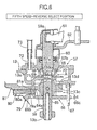
- the shift select shaft 59 can be stopped at nodal points in the three rotational positions by means of a detent mechanism 63 (Fig. 8).
- a shift arm 64 is fixed by a fixing pin 65 on the shift select shaft 59 which extends inside the case right half 13, and an interlock plate 66 is also supported on the shaft in a relatively rotatable manner such that the shift arm 64 is vertically sandwiched by the plate 64.
- the interlock plate 66 comprises a pair of upper and lower lock claws 66a, 66b, and the pair of lock claws 66a, 66b face the top and bottom respectively of a drive part 64a formed at the forward end of the shift arm 64.
- the interlock plate 66 comprises a guide channel 66c which extends in a direction perpendicular to the shift select shaft 59 and a rotation stopping pin 67 fixed on the case right half 13 engages with the guide channel 66c.
- the shift select shaft 59 has a lower half with a smaller diameter beneath a step-shaped first stopper surface 59b which is formed almost at its center in the longitudinal direction, and the upper surface of the inner circumference of a first spring seat 68 which fits in a slidable manner on the lower half of the shift select shaft 59 having the smaller diameter, engages with the first stopper surface 59b from the lower side, whereas the upper surface of the outer circumference of the first spring seat 68 is in contact with a first support surface 57b which is a lower surface of the cover member 57.
- a disc-shaped second spring seat 69 which is placed beneath the first spring seat 68 and fits in a slidable manner on the shift select shaft 59, the lower surface of the inner circumference thereof engages with a second stopper surface 66d which is formed on the upper surface of the interlock plate 66.
- a roughly cross-shaped opening 13c is formed on the bottom wall of the indentation 13a of the case right half 13, and the lower surface of the outer circumference of the second spring seat 69 is supported by four step-shaped second supporting surfaces 13d which are formed on the edge of the opening 13c.
- the upper and lower ends of a select spring 70 are supported between the lower surface of the first spring seat 68 and the upper surface of the second spring seat 69.
- the shift select shaft 59 when the shift select shaft 59 is in the three speed - fourth speed select position shown in Fig. 4, the upper surface of the inner circumference of the first spring seat 68 and the lower surface of the inner circumference of the second spring seat 69 which are supported in a slidable manner on the shift select shaft 59 and are forced by the select spring 70 in a direction such that they move apart from each other, are resiliently in contact with both the first stopper surface 59b of the shift select shaft 59 and with the second stopper surface 66d formed on the upper surface of the interlock plate 66, and the upper surface of the outer circumference of the first spring seat 68 and the lower surface of the outer circumference of the second spring seat 69 are supported by being in contact with the first support surface 57b of the cover member 57 and with the second support surfaces 13d of the indentation 13a respectively, and the shift select shaft 59 thus stops in a stable manner at the third speed - fourth speed select position.
- the shift select shaft 59 can be centered by forcing it to the third speed - fourth speed select position, which is the neutral position, by means of just one select spring 70, in comparison with the case in which the shift select shaft 59 is forced upwards and downwards by means of two springs, the number of parts and the cost can be reduced. Moreover, when two springs are supported on the shift select shaft 59, the length of the shift select shaft 59 inevitably increases, but by using only one spring it is possible to reduce the overall length of the shift select shaft 59.
- the internal space of the breather chamber 58 which is defined by the indentation 13a of the case right half 13 and the cover member 57 is connected to the internal space of the transmission case 11 via four through holes 71 which are formed between the inner circumference of the opening 13c and the outer circumference of the second spring seat 69 and is connected to the outside of the transmission case 11 via a breather tube 73 provided on the forward end of a breather pipe 72, which is integral with the cover member 57.
- a subassembly A is formed by assembling the shift select shaft 59, the first spring seat 68, the second spring seat 69, the select spring 70, the shift arm 64, the fixing pin 65 and the interlock plate 66 beforehand, onto the cover member 57, and by inserting this subassembly A into the opening 13c through the indentation 13a of the case right half 13 during assembly.
- the assembly operation can be outstandingly enhanced.
- the breather chamber 58 is defined by the indentation 13a of the case right half 13 and the cover member 57, and the first spring seat 68, the second spring seat 69 and the select spring 70 are housed inside the breather chamber 58, a single space functions as both the space forming the breather chamber 58 and the space for housing the first spring seat 68, the second spring seat 69 and the select spring 70, and it is possible to avoid an increase in the size of the transmission case 11 and the number of parts.
- the breather chamber 58 is connected to the internal space of the transmission case 11 via the four through holes 71 which are formed between the inner circumference of the opening 13c and the outer circumference of the second spring seat 69, and the shift arm 64 and the interlock plate 66 are positioned so as to adjoin each other beneath the through holes 71, oil can be effectively prevented from entering the breather chamber 58 due to the labyrinth effect.
- the two ends of a first speed - second speed shift rod 76 comprising the first speed - second speed shift fork 44
- the two ends of a third speed - fourth speed shift rod 77 comprising the third speed - fourth speed shift fork 46
- the two ends of a fifth speed - reverse shift rod 78 comprising the fifth speed shift fork 48 are supported in a slidable manner on the case left half 12 and the case right half 13 respectively.
- a first speed - second speed shift piece 79, a third speed - fourth speed shift piece 80 and a fifth speed - reverse shift piece 81 are fixed on the first speed - second speed shift rod 76, the third speed - fourth speed shift rod 77 and the fifth speed - reverse shift rod 78 respectively, and notches 79a, 80a, 81a formed at the forward ends of the three shift pieces 79, 80, 81 respectively are aligned vertically so that they can selectively engage with the drive part 64a provided at the forward end of the shift arm 64.
- the shift select shaft 59 when the shift select shaft 59 is in the third speed - fourth speed select position as shown in Fig. 4, since the drive part 64a of the shift arm 64 engages with the notch 80a of the third speed - fourth speed shift piece 80, the third speed - fourth speed shift rod 77 can be driven together with the third speed - fourth speed shift piece 80 from the neutral position to the third speed position or the fourth speed position by a circular movement of the shift select shaft 59.
- the locking claw 66b on the lower side of the interlock plate 66 engages with the notch 79a of the first speed - second speed shift piece 79, and the locking claw 66a on the upper side of the interlock plate 66 engages with the notch 81a of the fifth speed - reverse shift piece 81, and thus malfunctions of the first speed - second speed shift piece 79 and the fifth speed -reverse shift piece 81 can be prevented.
- the locking claw 66a on the upper side of the interlock plate 66 engages with the notch 81a of the fifth speed - reverse shift piece 81 and the notch 80a of the third speed - fourth speed shift piece 80, and thus malfunctions of the fifth speed - reverse shift piece 81 and the third speed - fourth speed shift piece 80 can be prevented.
- the locking claw 66b on the lower side of the interlock plate 66 engages with the notch 79a of the first speed - second speed shift piece 79 and the notch 80a of the third speed - fourth speed shift piece 80, and thus malfunctions of the first speed - second speed shift piece 79 and the third speed - fourth speed shift piece 80 can be prevented.
- a detent mechanism 82 is provided in order to stop the first speed - second speed shift rod 76 at nodal points so as to correspond to the first speed - second speed select position, the first speed position and the second speed position.
- a detent mechanism 83 is provided in order to stop the third speed - fourth speed shift rod 77 at nodal points so as to correspond to the third speed - fourth speed select position, the third speed position and the fourth speed position.
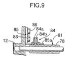
- a bracket 85 is fixed to the inner surface of the case right half 13 by means of two bolts 86, 86, and the reverse shift fork 50 is supported in a swingable manner on the bracket 85 via a fulcrum pin 87.
- a notch 50a which is interposed between the two side surfaces of the reverse idle gear 41 is formed at one end of the reverse shift fork 50 and a driven cam face a for reverse shift, a driven cam face b for neutral return and a driven cam face c for neutral hold are formed continuously at the other end, relative to the fulcrum pin 87, of the reverse shift fork 50.
- a drive cam face d for reverse shift which can come into contact with the driven cam face a for reverse shift and a drive cam face e for neutral return which can come into contact with the driven cam face b for neutral return and the driven cam face c for neutral hold, are formed continuously at the forward end of the drive cam 88, which is formed integrally with the fifth speed - reverse shift piece 81.
- a detent mechanism 84 for stopping the fifth speed - reverse shift rod 78 at nodal points to correspond to the fifth speed - reverse select position, the fifth speed position and the reverse position is provided at the forward end of an arm 85a which extends integrally from the bracket 85 supporting the reverse shift fork 50.
- the detent mechanism 84 comprises a detent ball 84b which is urged by a detent spring 84a, and this detent ball 84b can selectively engage with three indentations 81b to 81d (Fig. 10 to Fig. 12) which are formed on the fifth speed - reverse shift piece 81.
- the drive cam face d for reverse shift and the drive cam face e for neutral return of the drive cam 88 of the fifth speed - reverse shift piece 81 are in contact with the driven cam face a for reverse shift and the driven cam face c for neutral hold of the reverse shift fork 50 respectively, and the reverse idle gear 41 is at the neutral position which is at the right end on the reverse idle shaft Sr and is in contact with the end face 13i of the case right half 13.
- the main fifth speed gear 35 is linked to the main shaft Sm by the fifth speed shift fork 48, which is provided on the fifth speed - reverse shift rod 78, to establish the fifth speed gear shift stage (Fig. 1).
- the drive cam face e for neutral return of the drive cam 88 which operates integrally with the fifth speed - reverse shift rod 78 moves to slide along the driven cam face c for neutral hold of the reverse shift fork 50, and the reverse shift fork 50 remains stopped at the neutral position.
- a shaft support surface 13f of the shaft support hole 13e which supports the reverse idle shaft Sr comprises a major arc having an angle of about 250°, and a portion of the outer circumference of the reverse idle shaft Sr is exposed to the internal space of the case right half 13 through an opening 13g comprising a minor arc having an angle of about 110°.
- the size of the transmission case 11 can be reduced by allowing the reverse idle shaft Sr to approach the main shaft Sm as closely as possible without providing a special member for supporting the reverse idle shaft Sr or carrying out special processing.
- the present invention can be applied to an automatic transmission in which the shift/select operation is carried out by an actuator.
- a first spring seat and a second spring seat are supported in a slidable manner between a first stopper surface and a second stopper surface which are provided on a shift select shaft with a gap between them in the axial direction.
- the inner surfaces in the axial direction of the first and second spring seats are forced by a select spring in the direction in which they move away from each other to come into contact with the first and second stopper surfaces respectively.
- the outer surfaces in the axial direction of the first and second spring seats are supported on first and second support surfaces respectively provided in a transmission case.
Landscapes
- Engineering & Computer Science (AREA)
- General Engineering & Computer Science (AREA)
- Mechanical Engineering (AREA)
- Gear-Shifting Mechanisms (AREA)
- General Details Of Gearings (AREA)
Claims (2)
- Dispositif de changement de vitesses ayant un carter de boíte de vitesses (13), une pluralité de fourchettes de commande des vitesses (44, 46, 48), un arbre de sélection de vitesse (59), un levier de commande des vitesses (L), un ressort de sélection (70), des premier et second sièges de ressort (68, 69), et des première et seconde surfaces de butée (59b, 66d), pour sélectivement établir une pluralité d'étages de changement de vitesse dans lequel les fourchettes de commande des vitesses (44, 46, 48) sont actionnées par l'arbre de sélection de vitesse (59) supporté sur le carter de boíte de vitesses (13) via un arbre de changement de vitesse (64) qui sélectivement met en prise une pluralité de pièces de changement de vitesse (79, 80, 81) couplées aux fourchettes de commande des vitesses (44, 46, 48), l'arbre de sélection de vitesse (59) étant déplacé dans la direction axiale selon une opération de sélection du levier de commande des vitesses (L) et étant déplacé d'une manière circulaire selon une opération de changement du levier de commande des vitesses (L), dans lequel l'arbre de sélection de vitesse (59) est maintenu dans une position de sélection centrale de trois positions de sélection dans la direction axiale par la force résiliente du ressort de sélection (70), et dans lequel le premier siège de ressort (68) et le second siège de ressort (69) sont supportés d'une manière coulissante entre la première surface de butée (59b) et la seconde surface de butée (66d) prévues sur l'arbre de sélection de vitesse (59) avec un intervalle entre les première et seconde surfaces de butée (59b, 66d) dans la direction axiale, les surfaces intérieures dans la direction axiale des premier et second sièges de ressort (68, 69) étant forcés par le ressort de sélection (70) dans la direction dans laquelle les premier et second sièges de ressort (68, 69) s'éloignent l'un de l'autre à entrer en contact avec les première et seconde surfaces de butée (59b, 66d) respectivement, et les surfaces extérieures dans la direction axiale des premier et second sièges de ressort (68, 69) sont supportées sur les première et seconde surfaces de support (57b, 13d) respectivement prévues sur le carter de boíte de vitesses,
caractérisé en ce que
la seconde surface de butée (66d) est prévue sur une plaque de verrou (66), la plaque de verrou (66) étant supportée sur l'arbre de sélection de vitesse (59) de telle sorte qu'elle se déplace avec l'arbre de sélection de vitesse (59) dans la direction axiale de
celui-ci, alors que l'arbre de sélection de vitesse (59) peut tourner par rapport à la plaque de verrou (66), la plaque de verrou (66) venant en prise avec les pièces de changement de vitesse (79, 80, 81) qui ne sont pas actionnées par l'arbre de changement de vitesse pour empêcher un dysfonctionnement de ces pièces de changement de vitesse (79, 80, 81). - Dispositif de changement de vitesses selon la revendication 1, dans lequel les premier et second sièges de ressort (68, 69) et le ressort de sélection (70) sont logés à l'intérieur d'une chambre de reniflard (58) dans le carter de boíte de vitesses (13), et les première et seconde surfaces de support (57b, 13d) sont formées sur la paroi intérieure de la chambre de reniflard.
Applications Claiming Priority (3)
| Application Number | Priority Date | Filing Date | Title |
|---|---|---|---|
| JP29541999A JP3706778B2 (ja) | 1999-10-18 | 1999-10-18 | トランスミッションの変速装置 |
| JP29541999 | 1999-10-18 | ||
| US09/688,214 US6474188B1 (en) | 1999-10-18 | 2000-10-16 | Transmission gear shift system |
Publications (3)
| Publication Number | Publication Date |
|---|---|
| EP1094256A2 EP1094256A2 (fr) | 2001-04-25 |
| EP1094256A3 EP1094256A3 (fr) | 2003-05-07 |
| EP1094256B1 true EP1094256B1 (fr) | 2005-03-16 |
Family
ID=26560259
Family Applications (1)
| Application Number | Title | Priority Date | Filing Date |
|---|---|---|---|
| EP00122079A Expired - Lifetime EP1094256B1 (fr) | 1999-10-18 | 2000-10-11 | Dispositif de changement de vitesses |
Country Status (4)
| Country | Link |
|---|---|
| US (1) | US6474188B1 (fr) |
| EP (1) | EP1094256B1 (fr) |
| JP (1) | JP3706778B2 (fr) |
| CN (1) | CN1114056C (fr) |
Families Citing this family (11)
| Publication number | Priority date | Publication date | Assignee | Title |
|---|---|---|---|---|
| TW536597B (en) | 2001-06-29 | 2003-06-11 | Honda Motor Co Ltd | Changing system in manual transmission |
| JP4036424B2 (ja) * | 2001-06-29 | 2008-01-23 | 本田技研工業株式会社 | 手動変速機のチェンジ装置 |
| JP3908484B2 (ja) * | 2001-06-29 | 2007-04-25 | 本田技研工業株式会社 | 手動変速機の変速装置 |
| DE10253471A1 (de) * | 2002-11-16 | 2004-08-26 | Zf Friedrichshafen Ag | Schaltvorrichtung für ein Getriebe |
| EP1711727B1 (fr) * | 2004-02-03 | 2008-06-25 | GETRAG Getriebe- und Zahnradfabrik Hermann Hagenmeyer GmbH & Cie KG | Systeme de changement de vitesses |
| FR2888303A1 (fr) * | 2005-07-05 | 2007-01-12 | Renault Sas | Dispositif de billage et boite de vitesses a arbres paralleles |
| ITTO20080034A1 (it) * | 2008-01-16 | 2009-07-17 | Automac Di Bigi Ing Maurizio Sas | Dispositivo di comando per l'innesto delle marce per un cambio di velocita' di un veicolo con tamburo rotante presentante una camma principale e una camma ausiliaria |
| JP2011202679A (ja) * | 2010-03-24 | 2011-10-13 | Aisin Ai Co Ltd | 変速機のシフトアンドセレクトシャフトアッセンブリ |
| JP5475595B2 (ja) * | 2010-08-27 | 2014-04-16 | ダイハツ工業株式会社 | 車両用変速装置 |
| JP5872218B2 (ja) * | 2011-09-20 | 2016-03-01 | アイシン・エーアイ株式会社 | 手動変速機の誤操作防止装置 |
| JP6413849B2 (ja) * | 2015-03-04 | 2018-10-31 | スズキ株式会社 | 手動変速機のシフト装置 |
Family Cites Families (11)
| Publication number | Priority date | Publication date | Assignee | Title |
|---|---|---|---|---|
| US477742A (en) * | 1892-06-28 | Valve-register | ||
| FR1476760A (fr) * | 1965-12-30 | 1967-04-14 | Perfectionnements aux sélecteurs pour changements de vitesses adaptables aux véhicules automobiles | |
| DE3000577C2 (de) * | 1980-01-09 | 1983-01-27 | Zahnradfabrik Friedrichshafen Ag, 7990 Friedrichshafen | Schalteinrichtung für ein aus einem Haupt- und einem Zweibereichs-Gruppengetriebe bestehenden Zahnräder-Wechselgetriebe |
| JPS6215556Y2 (fr) * | 1981-03-30 | 1987-04-20 | ||
| EP0199731B1 (fr) * | 1984-03-17 | 1988-05-11 | ZF FRIEDRICHSHAFEN Aktiengesellschaft | Dispositif de changement de vitesse |
| JP2629871B2 (ja) | 1988-08-29 | 1997-07-16 | スズキ株式会社 | 車両用変速機 |
| CN2081919U (zh) * | 1990-03-30 | 1991-07-31 | 张德昆 | 刚性无级变速机构 |
| CN2078823U (zh) * | 1990-04-28 | 1991-06-12 | 宁波海洋渔业公司渔机厂 | 脉动无级变速器 |
| DE59303950D1 (de) * | 1992-08-10 | 1996-10-31 | Volkswagen Ag | Schalteinrichtung für ein Getriebe |
| US5385223A (en) * | 1994-02-16 | 1995-01-31 | Saturn Corporation | Shift control mechanism for a multi-speed countershaft transmission |
| US5560254A (en) * | 1994-07-25 | 1996-10-01 | Saturn Corporation | Shift control mechanism for a multi-speed countershaft transmission |
-
1999
- 1999-10-18 JP JP29541999A patent/JP3706778B2/ja not_active Expired - Fee Related
-
2000
- 2000-10-11 EP EP00122079A patent/EP1094256B1/fr not_active Expired - Lifetime
- 2000-10-16 US US09/688,214 patent/US6474188B1/en not_active Expired - Fee Related
- 2000-10-18 CN CN00131422A patent/CN1114056C/zh not_active Expired - Fee Related
Also Published As
| Publication number | Publication date |
|---|---|
| EP1094256A3 (fr) | 2003-05-07 |
| CN1293323A (zh) | 2001-05-02 |
| JP2001116142A (ja) | 2001-04-27 |
| JP3706778B2 (ja) | 2005-10-19 |
| US6474188B1 (en) | 2002-11-05 |
| CN1114056C (zh) | 2003-07-09 |
| EP1094256A2 (fr) | 2001-04-25 |
Similar Documents
| Publication | Publication Date | Title |
|---|---|---|
| EP1094248B1 (fr) | Système de ventilation | |
| EP1094256B1 (fr) | Dispositif de changement de vitesses | |
| EP0702172B1 (fr) | Boíte de vitesses commandée à la main | |
| CA1259823A (fr) | Transmission pour vehicule | |
| EP1094255B1 (fr) | Dispositif de changement de vitesses | |
| EP1271013B1 (fr) | Mécanisme selecteur pour boîte de vitesses manuelles | |
| EP1271014B1 (fr) | Système de changement de vitesses pour transmission manuelle | |
| US4472868A (en) | Method of assembling an automotive manual transmission | |
| US4483213A (en) | Select detent mechanism of an automotive manual transmission | |
| EP1233214B1 (fr) | Mechanisme de marche arrière pour une transmission de véhicule automobile | |
| CA2323384C (fr) | Systeme pour boite de vitesse de transmission | |
| US4539858A (en) | Shift control mechanism of an automotive manual transmission | |
| JP3547335B2 (ja) | マニュアルバルブレバーの位置決め構造 | |
| US4646584A (en) | Vehicular transmission select and shift mechanism | |
| JPH0125805Y2 (fr) | ||
| JP7779162B2 (ja) | 車両用変速機 | |
| JP3668689B2 (ja) | トランスミッション | |
| EP0059399B1 (fr) | Mécanisme de commande d'une boîte de changement de vitesses manuelle pour un véhicule | |
| JP2001116119A (ja) | トランスミッションのリバースアイドルシャフト支持構造 | |
| JPS6242189B2 (fr) | ||
| JPS61248963A (ja) | リバ−スチエツク機構 |
Legal Events
| Date | Code | Title | Description |
|---|---|---|---|
| PUAI | Public reference made under article 153(3) epc to a published international application that has entered the european phase |
Free format text: ORIGINAL CODE: 0009012 |
|
| AK | Designated contracting states |
Kind code of ref document: A2 Designated state(s): AT BE CH CY DE DK ES FI FR GB GR IE IT LI LU MC NL PT SE |
|
| AX | Request for extension of the european patent |
Free format text: AL;LT;LV;MK;RO;SI |
|
| PUAL | Search report despatched |
Free format text: ORIGINAL CODE: 0009013 |
|
| AK | Designated contracting states |
Designated state(s): AT BE CH CY DE DK ES FI FR GB GR IE IT LI LU MC NL PT SE |
|
| AX | Request for extension of the european patent |
Extension state: AL LT LV MK RO SI |
|
| 17P | Request for examination filed |
Effective date: 20030528 |
|
| 17Q | First examination report despatched |
Effective date: 20030811 |
|
| AKX | Designation fees paid |
Designated state(s): DE FR GB |
|
| GRAP | Despatch of communication of intention to grant a patent |
Free format text: ORIGINAL CODE: EPIDOSNIGR1 |
|
| GRAS | Grant fee paid |
Free format text: ORIGINAL CODE: EPIDOSNIGR3 |
|
| GRAA | (expected) grant |
Free format text: ORIGINAL CODE: 0009210 |
|
| AK | Designated contracting states |
Kind code of ref document: B1 Designated state(s): DE FR GB |
|
| REG | Reference to a national code |
Ref country code: GB Ref legal event code: FG4D |
|
| REG | Reference to a national code |
Ref country code: IE Ref legal event code: FG4D |
|
| REF | Corresponds to: |
Ref document number: 60018672 Country of ref document: DE Date of ref document: 20050421 Kind code of ref document: P |
|
| PLBE | No opposition filed within time limit |
Free format text: ORIGINAL CODE: 0009261 |
|
| STAA | Information on the status of an ep patent application or granted ep patent |
Free format text: STATUS: NO OPPOSITION FILED WITHIN TIME LIMIT |
|
| ET | Fr: translation filed | ||
| 26N | No opposition filed |
Effective date: 20051219 |
|
| PGFP | Annual fee paid to national office [announced via postgrant information from national office to epo] |
Ref country code: GB Payment date: 20101006 Year of fee payment: 11 |
|
| PGFP | Annual fee paid to national office [announced via postgrant information from national office to epo] |
Ref country code: FR Payment date: 20111103 Year of fee payment: 12 |
|
| REG | Reference to a national code |
Ref country code: DE Ref legal event code: R084 Ref document number: 60018672 Country of ref document: DE Effective date: 20120813 |
|
| GBPC | Gb: european patent ceased through non-payment of renewal fee |
Effective date: 20121011 |
|
| REG | Reference to a national code |
Ref country code: FR Ref legal event code: ST Effective date: 20130628 |
|
| PG25 | Lapsed in a contracting state [announced via postgrant information from national office to epo] |
Ref country code: GB Free format text: LAPSE BECAUSE OF NON-PAYMENT OF DUE FEES Effective date: 20121011 |
|
| PG25 | Lapsed in a contracting state [announced via postgrant information from national office to epo] |
Ref country code: FR Free format text: LAPSE BECAUSE OF NON-PAYMENT OF DUE FEES Effective date: 20121031 |
|
| PGFP | Annual fee paid to national office [announced via postgrant information from national office to epo] |
Ref country code: DE Payment date: 20180925 Year of fee payment: 19 |
|
| REG | Reference to a national code |
Ref country code: DE Ref legal event code: R119 Ref document number: 60018672 Country of ref document: DE |
|
| PG25 | Lapsed in a contracting state [announced via postgrant information from national office to epo] |
Ref country code: DE Free format text: LAPSE BECAUSE OF NON-PAYMENT OF DUE FEES Effective date: 20200501 |