EP1095549A1 - Anbauschnittstelle zur Kopplung von Arbeitsgeräten an ein Arbeitsfahrzeug - Google Patents
Anbauschnittstelle zur Kopplung von Arbeitsgeräten an ein Arbeitsfahrzeug Download PDFInfo
- Publication number
- EP1095549A1 EP1095549A1 EP00123188A EP00123188A EP1095549A1 EP 1095549 A1 EP1095549 A1 EP 1095549A1 EP 00123188 A EP00123188 A EP 00123188A EP 00123188 A EP00123188 A EP 00123188A EP 1095549 A1 EP1095549 A1 EP 1095549A1
- Authority
- EP
- European Patent Office
- Prior art keywords
- connecting elements
- frame
- vehicle
- triangle
- interface according
- Prior art date
- Legal status (The legal status is an assumption and is not a legal conclusion. Google has not performed a legal analysis and makes no representation as to the accuracy of the status listed.)
- Granted
Links
Images

Classifications
-
- A—HUMAN NECESSITIES
- A01—AGRICULTURE; FORESTRY; ANIMAL HUSBANDRY; HUNTING; TRAPPING; FISHING
- A01B—SOIL WORKING IN AGRICULTURE OR FORESTRY; PARTS, DETAILS, OR ACCESSORIES OF AGRICULTURAL MACHINES OR IMPLEMENTS, IN GENERAL
- A01B59/00—Devices specially adapted for connection between animals or tractors and agricultural machines or implements
- A01B59/06—Devices specially adapted for connection between animals or tractors and agricultural machines or implements for machines mounted on tractors
- A01B59/061—Devices specially adapted for connection between animals or tractors and agricultural machines or implements for machines mounted on tractors specially adapted for enabling connection or disconnection controlled from the driver's seat
- A01B59/062—Devices specially adapted for connection between animals or tractors and agricultural machines or implements for machines mounted on tractors specially adapted for enabling connection or disconnection controlled from the driver's seat the connection comprising a rigid interface frame on the tractor
-
- A—HUMAN NECESSITIES
- A01—AGRICULTURE; FORESTRY; ANIMAL HUSBANDRY; HUNTING; TRAPPING; FISHING
- A01B—SOIL WORKING IN AGRICULTURE OR FORESTRY; PARTS, DETAILS, OR ACCESSORIES OF AGRICULTURAL MACHINES OR IMPLEMENTS, IN GENERAL
- A01B59/00—Devices specially adapted for connection between animals or tractors and agricultural machines or implements
- A01B59/06—Devices specially adapted for connection between animals or tractors and agricultural machines or implements for machines mounted on tractors
- A01B59/066—Devices specially adapted for connection between animals or tractors and agricultural machines or implements for machines mounted on tractors of the type comprising at least two lower arms and one upper arm generally arranged in a triangle, e.g. three-point hitches
- A01B59/068—Devices specially adapted for connection between animals or tractors and agricultural machines or implements for machines mounted on tractors of the type comprising at least two lower arms and one upper arm generally arranged in a triangle, e.g. three-point hitches the lower arms being lifted or lowered by power actuator means provided externally on the tractor
Definitions
- the invention relates to an attachment interface for coupling Work tools on a work vehicle with a Coupling frame, the coupling means for fastening the Has tools, and with at least six length-adjustable connecting elements, the first of which End articulated to the vehicle and their respective second end articulated to the coupling frame stands.
- US-A-3,432,184 describes an attachment for one Tractor with a triangular plate on which one Coupling plate can be attached, which is the mounting of attachments serves.
- Run between the tractor frame and the plate seven actuators adjustable in length, with their first end each at four articulation points of the tractor frame are articulated.
- Two essentially horizontal tops Actuators are aligned in a V-shape and run with them their second ends at an upper articulation point of the frame together.
- Two essentially horizontal lower actuators are aligned parallel to each other and grip with theirs second ends at a lower articulation point of the frame on.
- Two oblique stroke actuators are parallel to each other aligned.
- the object underlying the invention is seen in a mounting interface or a device coupling device to provide the type mentioned, which is also a lateral steering function and a lateral displacement of the Tool allows, which is particularly lateral Forces exerted by the implement when operating on the vehicle transmits, reduce.
- the mounting interface should all Allow movement types (six degrees of freedom) and the Expand functions of known mounting interfaces. Of Another is to enable easy coupling of devices be, different types of coupling for attachment of tools on the coupling frame are possible.
- the length-adjustable connecting elements should be used with your Operation should not be subjected to any significant bending forces.
- a closed kinematic chain is a Gear consisting of limbs (legs) and joints, in which the chain end points articulated on a common base body are.
- a closed kinematic chain is a Gear consisting of limbs (legs) and joints, in which the chain end points articulated on a common base body are.
- two Fasteners that one end of the vehicle body (Base body) and at the other ends hinged to the coupling frame are a closed kinematic chain.
- the connecting elements are preferably in the manner of a Hexapods arranged.
- Hexapods are one special arrangement of six length-adjustable legs, such as them in the context of a method of controlling a Motorized coordinate measuring machine in DE-A-197 20 049 and in Connection with the description of robot kinematics in the Industry magazine “mün here” Würzburg 105 (1999) 21, Page 44 has been described.
- Hexapods only have closed ones Chains with two legs each (connecting elements). It So far it has not been recognized that this is the hexapod underlying principle also for training a Attachment interface for work vehicles, where it is less on location precision than on mastering large ones static and dynamic forces arrive.
- At least six independently adjustable in length Fasteners are used, the first ends of which are articulated the vehicle and its second ends articulated with the Coupling frames are connected.
- the first ends of the Fasteners are essentially in the corner points of a triangle on the vehicle, articulated in each case at least two fasteners near one of these Corner points is articulated.
- the second ends of the Fasteners are essentially in the corner points of a frame-side triangle, here too in each case at least two connecting elements in the vicinity of one these key points are articulated.
- the positions of the device and / or vehicle side Articulation points of the connecting elements can be relative to one another can be freely chosen within wide limits. Near one The corner can also have several spatially separated Linkage elements can be provided for a connecting element, so that the connecting element optionally in one of these Link elements can hang. By such a change in Guide point positions can have different configurations select and set.
- the Fasteners only on push and pull and not on Bending stresses, which makes their interpretation easier.
- the mounting interface according to the invention can be for example on the back or on the front of a Work vehicle, especially an agricultural tractor, arrange.
- a Work vehicle especially an agricultural tractor
- parallel mechanisms enables the parallel arrangement of the adjustable fasteners the movements of the Coupling frame in six degrees of freedom (3 rotations, 3 Translations).
- the add-on interface intelligent functions of the Attachment interface can be implemented, which is the case with the usual Three-point attachment is missing or for the additional mechanical Adjusting devices or additional hydraulic cylinders (e.g. hydraulic top link, hydraulic lifting strut, hydraulic Side stabilization and others) had to be provided, without the versatility of the solution according to the invention could be achieved.
- the lengths of the connecting elements can be largely set independently.
- the ratio of lengths each other is arbitrary by a suitable control adjustable.
- the implement can be parallel (to the side, in height and in the vehicle's longitudinal direction), the angle of attack of the Adjust implement (rotation about an axis transverse to Vehicle or around a vertical axis) and the implement compared to the work vehicle around a vehicle longitudinal axis twist.
- the attachment interface according to the invention enables in particular a lateral steering function of the coupling frame and a lateral shift of the tools.
- the mounting interface according to the invention thus has the special advantage that in addition to providing the Functions of a standard three-point attachment interface (lifting and lowering an implement) also easy coupling of Enables equipment on the work vehicle without that whole vehicle or implement must be moved. It is also possible by changing the length of the connecting elements in addition to a height adjustment and one Side adjustment the distance between the rear (or the Front) of the work vehicle and the coupling frame.
- the Pairing is when using different types of coupling for the Attachment of tools to the coupling frame possible. It is also an automatic coupling and uncoupling of Tools or attachments when the vehicle is at a standstill possible.
- the implement is in operation steerable and laterally displaceable. Lateral forces that The implement can be transferred to the tractor by means of a reduce suitable lateral displacement of the implement. By optimizing the side forces, the Maneuverability and maneuverability of the overall system (Work vehicle and work equipment) improve.
- the angle between the longitudinal axis of the vehicle and that of the Implement can be set arbitrarily (the angles between the areas that are caused by the vehicle's articulation points or are spanned by the frame-side articulation points, changed).
- the angle of attack between Adjust the device and floor regardless of the lifting height or maintained over a large stroke range.
- the attachment interface enables one Swiveling the implement while driving.
- the Tool can also be moved sideways to for example when driving down a slope the focus of the To move the entire system towards the slope. It can also be one Reducing the turning radius and improving the Maneuverability of the entire system through automatic Panning of the implement can be achieved when cornering, so that, for example, when driving through narrow passages Collisions avoided by swinging out the attachment become.
- Coordinate transformation can be calculated from the Control signals for setting the lengths of the Fasteners are derived so that the Coupling frame is adjusted to the desired position.
- the position of the coupling frame and so that the implement set very precisely so that the Quality of work compared to a conventional three-point hitch can increase significantly.
- Any length can be stored in a working memory of the control of the fasteners stored and as needed by the Control electronics are reproduced, so that Standard settings or duty cycles, for example for lowering and lifting the implement, easily and quickly repeat.
- the control electronics By connecting the control electronics with a field mapping and / or a GPS file implement effective working depth control.
- the articulation points of the first and second ends of the Connecting elements are preferably designed so that they an all-round pivoting of the connecting elements with respect of the vehicle or the coupling frame.
- a preferred embodiment of the invention provides that the Coupling frame is essentially triangular. in the At least each area of each corner of the coupling frame grips two length-adjustable connecting elements with one of their Articulated ends. On the coupling frame, for example in the area its corners, can be coupling means for receiving a working or Attachment be arranged. There are many known coupling means to choose from.
- a so-called single-phase couplers can be used. This exists from two V-shaped legs, which are in an upper Vertex are connected together and wedge shaped after diverge below. How the Single phase coupler is similar to that in US-A-3,432,184 described plate that accommodate a coupling plate can The top vertex and the two bottom free ones The ends of the single-phase coupler form a triangle. In the field of Corners of this triangle each have at least one end articulated two length-adjustable connecting elements.
- the frame-side triangle and the vehicle-side triangle as similar to one another Triangles are formed. These are the triangles preferably around isosceles or equilateral triangles.
- the symmetrical arrangement facilitates the control of the Fasteners through which the coupling frame in six Degrees of freedom is adjusted or moved.
- the triangle on the frame and the Vehicle-side triangle in a basic or starting position essentially rotated by 180 ° to each other.
- the vehicle-side triangle is smaller than the triangle on the device side.
- At least one connecting element is a hydraulic cylinder, in particular a double-acting hydraulic cylinder, or an electromechanical adjustment element.
- Hydraulic cylinders can easily handle large forces, for example, to lift the implement, while electromechanical adjustment elements are simple offer controllable adjustment.
- the pressure of Hydraulic cylinder can be detected and used to determine the mass Working tools are used.
- a Control device may be provided, which due to Required lengths of the connecting elements calculated and outputs corresponding control signals.
- the Setpoints are set, for example, by an operator set. However, you can also use a parent Control, for example a position control, can be specified.
- the control signals are calculated on the basis of the specific ones geometric arrangement of the connecting elements and their Articulation points.
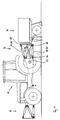
- FIG. 1 shows a tractor 10 on which one front mounting interface 12 and a rear Interface 14 are articulated. On the rear Mounting interface 14, an order combination 16 is mounted, while at the front mounting interface 12 currently none Tool is attached. Details of the mounting interfaces are shown in Figure 2. Same or corresponding Components have been given the same reference numbers.
- the mounting interface of the illustrated embodiment essentially contains a triangular coupling frame 30 and six length-adjustable connecting elements 18, 20, 22, 24, 26, 28, whose first ends are articulated on the vehicle body 32, e.g. B. on the differential housing or on the vehicle frame, and the respective second ends of which are articulated on the coupling frame 30 are attached.
- the vehicle-side articulation points of the connecting elements 18, 20, 22, 24, 26, 28 are essentially in the corner points 34, 36, 38 of a triangle on the vehicle.
- One of these cornerstones 34 is deep and in the transverse direction of the vehicle in the Center.
- the two other key points 36, 38 of the vehicle triangle are at the same height with each other above the deep corner point 34 and are symmetrical to Vehicle transverse direction arranged.
- the frame side Articulation points of the connecting elements 18, 20, 22, 24, 26, 28 are essentially in the corner points 40, 42, 44 one frame-side triangle.
- One of these corner points 40 is high, while the two other corner points 42, 44 of the frame side Triangle with each other at the same height and below the high corner point 40 are arranged.
- equilateral triangles In the vehicle-side and the frame-side triangle in the present exemplary embodiment equilateral triangles. They are also isosceles triangles possible. Isosceles triangles with a comparatively large extension in the vertical direction can then of Be an advantage if the vertical forces are particularly high Mounting interface must be included.
- a first connector 18 is at one end near the low-lying vehicle-side corner point 34 and other ends in close to a first of the two deep frame side Corner points 42 articulated.
- a second connecting element 20 is one end near the low-lying vehicle-side Vertex 34 and at the other near a second of the hinged two deep frame-side corner points 44.
- a third connector 22 is near one end a first of the two high-lying vehicle-side Vertices 36 and other ends near the second deep lying frame-side corner points 44 articulated.
- a fourth Link 24 is high at one end near the first lying vehicle-side corner point 36 and other ends in the Articulated near the high-lying frame-side corner point 40.
- a fifth connector 26 is near one end a second of the two high-lying vehicle-side Corner points 38 and at the other near the high frame-side corner point 40 articulated.
- a sixth Connector 28 is one end near the second high-lying vehicle-side corner 38 and other ends in the vicinity of the first low-lying frame-side corner point 42 articulated.
- the connecting elements 18, 20, 22, 24, 26, 28 are mutually positioned in a triangular arrangement such that neighboring ones Connecting elements 18, 20, 22, 24, 26, 28 with one side of the vehicle-side triangle or the frame-side triangle each form a triangle.
- the vehicle-side triangle (34, 36, 38) and the frame-side triangle (40, 42, 44) similar triangles that are shown in their Starting position are rotated by 180 ° to each other.
- the vehicle-side triangle is slightly smaller than the frame-side one Triangle. This has, as is apparent from Fig. 1, z. B. result that in terms of vertical alignment, the top ones Connecting elements 24, 26 are not parallel to the lower ones Connecting elements 18, 20 run.
- the fasteners 18, 20, 22, 24, 26, 28 converge into one on the vehicle side vertical instantaneous pole F, d. H. their axes run in that Current pole F together.
- the connecting elements 18, 20, 22, 24, 26, 28 further converge into one not shown horizontal instantaneous pole that does not match the vertical Momentary pole must coincide.
- At the instantaneous pole F (also Momentary center) is a virtual one Place where the virtual introduction of the equipment workers in the agricultural tractor takes place.
- the Connecting elements 18, 20, 22, 24, 26, 28 can be the Instantaneous pole F in the vehicle's longitudinal direction, in the vehicle's transverse direction and move it vertically. In the floating position the resultant of the implement goes through the instantaneous pole F. By adjusting the position of the instantaneous pole F, the rear axle load caused by a pulling force vary.
- the vertical orientation of the coupling frame 30 can The lifting and lowering of the implement 16 are maintained, d. H. parallel lifting and lowering is possible. This is particularly useful for tillage PTO operation is an advantage as it is raised and lowered of the implement the alignment of the vehicle side PTO 46 and the orientation of the implement-side PTO 48 can be maintained so that the Angular speed of the PTO not as a result of Stroke changes.
- connecting elements 18, 20, 22, 24, 26, 28 are, for example, double-sided acting hydraulic cylinders or electromechanical Adjustment elements.
- the articulation points of the connecting elements 18, 20, 22, 24, 26, 28 are designed such that they are a all-round pivoting relative to the vehicle body 32 or enable the coupling frame 30.
- it can be Acting ball or universal joints.
- Fig. 2 shows a mounting interface with a closed triangular coupling frame 30 with three legs.
- the Coupling frame 30 carries in its corner points on the Side facing away from the vehicle has an upwardly open hook 52, 54, 56 for attaching tools.
- On the coupling frame 30 can further coupling means, not shown as well as supply and measuring connections.
- Coupling frame can also be a so-called, not shown Single phase couplers are used, essentially two Has thighs and as an upside down V is formed (the lower leg of the in Fig. 2nd shown frame is missing).
- the fasteners grip at the base and at the free ends of the V.
- the Single-phase coupler can be a suitably trained Attach the frame part of the attachment and if necessary lock, making the free legs of the V a sufficient Gain stability. Fastening hooks as in Fig. 2 are dispensed with here.
Landscapes
- Life Sciences & Earth Sciences (AREA)
- Zoology (AREA)
- Engineering & Computer Science (AREA)
- Mechanical Engineering (AREA)
- Soil Sciences (AREA)
- Environmental Sciences (AREA)
- Agricultural Machines (AREA)
Abstract
Description
- Fig. 1
- die Seitenansicht eines Arbeitsfahrzeugs mit einer frontseitigen und einer heckseitigen erfindungsgemäß ausgebildeten Anbauschnittstelle und mit einer Bestellkombination und
- Fig. 2
- die perspektivische Prinzipskizze einer heckseitigen erfindungsgemäßen Anbauschnittstelle.
Claims (13)
- Anbauschnittstelle zur Kopplung von Arbeitsgeräten (16) an ein Arbeitsfahrzeug (10) mit einem Kopplungsrahmen (30), der Kopplungsmittel (52, 54, 56) für die Befestigung der Arbeitsgeräte (16) aufweist, und mit wenigstens sechs längenverstellbaren Verbindungselementen (18, 20, 22, 24, 26, 28), deren jeweils erstes Ende gelenkig mit dem Fahrzeug (10) verbindbar ist und deren jeweils zweites Ende gelenkig mit dem Kopplungsrahmen (30) in Verbindung steht, dadurch gekennzeichnet, daß die sechs Verbindungselemente (18, 20, 22, 24, 26, 28) in geschlossenen kinematischen Ketten angeordnet sind und die Bewegung des Kopplungsrahmens (30) in sechs Freiheitsgraden ermöglichen.
- Anbauschnittstelle nach Anspruch 1, dadurch gekennzeichnet, daß die Verbindungselemente (18, 20, 22, 24, 26, 28) nach Art eines Hexapoden angeordnet sind.
- Anbauschnittstelle nach Anspruch 1 oder 2, dadurch gekennzeichnet, daß die Verbindungselemente (18, 20, 22, 24, 26, 28) fahrzeugseitig und/oder koppelrahmenseitig in den Eckpunkten (34, 36, 38; 40, 42, 44) verschiedener geometrischer Figuren, wie Dreieck, Viereck, Trapez oder Sechseck, angreifen, wobei die jeweiligen Eckpunkte nicht notwendiger Weise in einer Ebene liegen.
- Anbauschnittstelle nach Anspruch 1 oder 3, dadurch gekennzeichnet, daß die traktorseitigen Anlenkpunkte der unteren Aktuatoren (18, 20) so weit auseinander liegen, daß die unteren Aktuatoren (18, 20) nicht in den Bewegungsraum einer zwischen ihnen durchgeführten Zapfwelle eingreifen.
- Anbauschnittstelle nach Anspruch 1 oder 4, dadurch gekennzeichnet, daß die ersten Enden der Verbindungselemente (18, 20, 22, 24, 26, 28) im wesentlichen in den Eckpunkten (34, 36, 38) eines fahrzeugseitigen Dreiecks angelenkt sind und jeweils wenigstens zwei Verbindungselemente (18, 20, 22, 24, 26, 28) in jedem dieser Eckpunkte (34, 36, 38) zusammenlaufen und daß die zweiten Enden der Verbindungselemente (18, 20, 22, 24, 26, 28) im wesentlichen in den Eckpunkten (40, 42, 44) eines rahmenseitigen Dreiecks angelenkt sind und jeweils wenigstens zwei Verbindungselemente (18, 20, 22, 24, 26, 28) in jedem dieser Eckpunkte (40, 42, 44) zusammenlaufen.
- Anbauschnittstelle nach einem der Ansprüche 1 bis 5, dadurch gekennzeichnet, daß der Koppelrahmen (30) im wesentlichen als dreieckförmiger Rahmen ausgebildet ist und daß im Bereich jeder Ecke des Rahmens jeweils ein Ende wenigstens zweier längenverstellbarer Verbindungselemente (18, 20, 22, 24, 26, 28) gelenkig angreift.
- Anbauschnittstelle nach einem der Ansprüche 1 bis 6, dadurch gekennzeichnet, daß der Koppelrahmen im wesentlichen nach Art eines zweischenkligen, V-förmigen Einphasenkupplers ausgebildet ist und daß im Bereich des Scheitels und im Bereich der freien Enden des Einphasenkupplers jeweils ein Ende wenigstens zweier längenverstellbarer Verbindungselemente (18, 20, 22, 24, 26, 28) gelenkig angreift.
- Anbauschnittstelle nach einem der Ansprüche 1 bis 7, dadurch gekennzeichnet, daß die Anlenkstellen der ersten und zweiten Enden der Verbindungselemente (18, 20, 22, 24, 26, 28) ein allseitiges Verschwenken der Verbindungselemente (18, 20, 22, 24, 26, 28) bezüglich des Fahrzeugs (10) bzw. des Kopplungsrahmens (30) zulassen.
- Anbauschnittetelle nach einem der Ansprüche 5 bis 8, dadurch gekennzeichnet, daß das rahmenseitige Dreieck und das fahrzeugseitige Dreieck zueinander ähnliche Dreiecke sind.
- Anbauschnittstelle nach einem der Ansprüche 5 bis 9, dadurch gekennzeichnet, daß das rahmenseitige Dreieck und das fahrzeugseitige Dreieck gleichseitige oder gleichschenklige Dreiecke sind.
- Anbauschnittetelle nach einem der Ansprüche 5 bis 10, dadurch gekennzeichnet, daß das rahmenseitige Dreieck und das fahrzeugseitige Dreieck in einer Grundstellung der Anbauschnittstelle im wesentlichen um 180° zueinander verdreht sind.
- Anbauschnittstelle nach einem der Ansprüche 1 bis 11, dadurch gekennzeichnet, daß die Verbindungselemente (18, 20, 22, 24, 26, 28) konvergent angeordnet sind und insbesondere das fahrzeugseitige Dreieck kleiner ist als das rahmenseitige Dreieck.
- Anbauschnittstelle nach einem der Ansprüche 1 bis 12, dadurch gekennzeichnet, daß wenigstens ein Verbindungselement (18, 20, 22, 24, 26, 28) einen Hydraulikzylinder, insbesondere einen doppelseitig wirkenden Hydraulikzylinder, oder wenigstens ein elektromechanisches Verstellelement enthält.
Applications Claiming Priority (2)
| Application Number | Priority Date | Filing Date | Title |
|---|---|---|---|
| DE19951840 | 1999-10-28 | ||
| DE19951840A DE19951840B4 (de) | 1999-10-28 | 1999-10-28 | Anbauschnittstelle zur Kopplung von Arbeitsgeräten an ein Arbeitsfahrzeug |
Publications (2)
| Publication Number | Publication Date |
|---|---|
| EP1095549A1 true EP1095549A1 (de) | 2001-05-02 |
| EP1095549B1 EP1095549B1 (de) | 2004-05-26 |
Family
ID=7927111
Family Applications (1)
| Application Number | Title | Priority Date | Filing Date |
|---|---|---|---|
| EP00123188A Expired - Lifetime EP1095549B1 (de) | 1999-10-28 | 2000-10-26 | Anbauschnittstelle zur Kopplung von Arbeitsgeräten an ein Arbeitsfahrzeug |
Country Status (6)
| Country | Link |
|---|---|
| US (1) | US6321851B1 (de) |
| EP (1) | EP1095549B1 (de) |
| AR (1) | AR032288A1 (de) |
| AT (1) | ATE267508T1 (de) |
| BR (1) | BR0005106A (de) |
| DE (2) | DE19951840B4 (de) |
Cited By (10)
| Publication number | Priority date | Publication date | Assignee | Title |
|---|---|---|---|---|
| EP1199194A3 (de) * | 2000-10-20 | 2002-11-06 | Deere & Company | Vorrichtung zum Kuppeln eines Fahrzeugs mit einem Gerät oder Anhänger |
| EP1360886A1 (de) | 2002-05-11 | 2003-11-12 | Deere & Company | Anbauvorrichtung für ein Arbeitsfahrzeug |
| WO2003094591A1 (de) * | 2002-05-11 | 2003-11-20 | Deere & Company | Vorrichtung zur kopplung zweier einheiten aneinander |
| EP1609346A1 (de) | 2004-06-21 | 2005-12-28 | Deere & Company | Bewegliches Schnittstellensystem mit mehreren Freiheitsgraden |
| EP1726199A1 (de) * | 2005-05-23 | 2006-11-29 | Deere & Company | Dreipunkt-Geräteanbau für einen zum Wein- und/oder Obstbau dienenden Traktor |
| ITMI20091262A1 (it) * | 2009-07-16 | 2011-01-17 | Dragone S R L Con Unico Socio | Macchina agricola per il trattamento di piante preferibilmente disposte in filari |
| RU2427995C1 (ru) * | 2010-02-24 | 2011-09-10 | Государственное образовательное учреждение высшего профессионального образования "Алтайский государственный технический университет им. И.И. Ползунова" (АлтГТУ) | Фронтальная навеска трактора |
| EP3498065A1 (de) * | 2017-12-13 | 2019-06-19 | Deere & Company | Verfahren zur bewegungssteuerung eines dreipunkt-krafthebers eines traktors |
| WO2020081111A1 (en) * | 2018-10-19 | 2020-04-23 | Cowley Daniel J | Mechanism combining articulation and side-shift |
| WO2021089879A1 (en) * | 2019-11-08 | 2021-05-14 | Davdor Limited | Tractor hitch assembly |
Families Citing this family (55)
| Publication number | Priority date | Publication date | Assignee | Title |
|---|---|---|---|---|
| EP1199622B1 (de) | 2000-10-20 | 2007-12-12 | Deere & Company | Bedienungselement |
| DE10111609A1 (de) * | 2001-03-10 | 2002-09-12 | Deere & Co | Bedienungselement |
| DE10111529A1 (de) | 2001-03-10 | 2002-09-12 | Deere & Co | Vorrichtung zum Koppeln eines Gerätes an einem Arbeitsfahrzeug |
| DE10114092A1 (de) | 2001-03-22 | 2002-09-26 | Deere & Co | Geräteschnittstelle zwischen Arbeitsfahrzeug und Gerät |
| DE10114091A1 (de) | 2001-03-22 | 2002-09-26 | Deere & Co | Steuervorrichtung für eine Fahrzeuganbauschnittstelle |
| DE10120732A1 (de) | 2001-04-27 | 2002-10-31 | Deere & Co | Anbauschnittstelle zwischen Arbeitsfahrzeug und Arbeitsgeräten sowie Steuereinrichtung |
| RU2210877C2 (ru) * | 2001-05-28 | 2003-08-27 | Государственное учреждение Татарский научно-исследовательский институт сельского хозяйства | Широкозахватный блочно-модульный сельскохозяйственный агрегат "кумаз" |
| DE10247058A1 (de) | 2002-10-09 | 2004-04-22 | Deere & Company, Moline | Geräteschnittstelle zur Kopplung von Arbeitsgeräten an ein Arbeitsfahrzeug und Ventilanordnung |
| AU2003293956A1 (en) * | 2002-12-19 | 2004-07-14 | Agco Sa | Automated hitching system |
| RU2244389C2 (ru) * | 2002-12-26 | 2005-01-20 | Алтайский государственный технический университет им. И.И. Ползунова (АлтГТУ) | Фронтальная навеска трактора |
| AU2003900744A0 (en) * | 2003-01-15 | 2003-03-06 | Justoy Pty Ltd | A tow hitch arrangement |
| FR2850525B1 (fr) * | 2003-01-31 | 2006-01-13 | Indust Design | Systeme d'accrochage d'outil pour vehicule de travaux et vehicule de travaux equipe d'un tel systeme d'accrochage |
| RU2241321C1 (ru) * | 2003-04-09 | 2004-12-10 | Государственное научное учреждение Поволжский научно-исследовательский институт эколого-мелиоративных технологий | Навесное устройство трактора |
| RU2261569C2 (ru) * | 2003-04-28 | 2005-10-10 | Кубанский государственный аграрный университет | Навесное устройство |
| RU2243635C1 (ru) * | 2003-05-12 | 2005-01-10 | Государственное Научное Учреждение Северо-Западный Научно-исследовательский Институт Механизации и Электрификации Сельского Хозяйства (ГНУ СЗНИИМЭСХ) | Сцепное устройство комбинированного агрегата |
| RU2246810C1 (ru) * | 2003-05-29 | 2005-02-27 | Волгоградская государственная сельскохозяйственная академия | Рычажно-шарнирный четырёхзвенный механизм навески для соединения сельскохозяйственных орудий и машин с рамой агрегатируемого трактора |
| RU2245609C1 (ru) * | 2003-06-03 | 2005-02-10 | Государственное научное учреждение Прикаспийский научно-исследовательский институт аридного земледелия РАСН | Рычажно-шарнирный четырехзвенный механизм навески для соединения сельскохозяйственных орудий и машин с рамой агрегатируемого трактора |
| RU2259030C1 (ru) * | 2004-03-15 | 2005-08-27 | Волгоградский государственный технический университет (ВолгГТУ) | Тракторный агрегат |
| GB2415354A (en) * | 2004-06-22 | 2005-12-28 | Agco Sa | Tractor front hitch |
| AT502864A3 (de) | 2004-10-11 | 2008-08-15 | Ehrenleitner Franz | Parallelkinematischer roboter |
| AT502980B1 (de) * | 2004-10-11 | 2008-06-15 | Ehrenleitner Franz | Parallelkinematik, insbesondere knickarm |
| AT503729B1 (de) * | 2004-10-11 | 2008-06-15 | Ehrenleitner Franz | Parallelkinematik, insbesondere hubroboter |
| AT502426B1 (de) * | 2004-10-11 | 2008-06-15 | Ehrenleitner Franz | Parallelkinematik, insbesondere hubtisch |
| US7681657B2 (en) * | 2004-12-09 | 2010-03-23 | Deere & Company | Debris guard |
| DE102005017578A1 (de) * | 2005-04-16 | 2006-10-26 | Deere & Company, Moline | Dreipunkt-Geräteanbau für ein landwirtschaftliches oder industrielles Nutzfahrzeug |
| US8602153B2 (en) * | 2007-08-06 | 2013-12-10 | Extendquip Llc | Extendable frame work vehicle |
| DE102007046890A1 (de) * | 2007-09-28 | 2009-04-09 | Claas Selbstfahrende Erntemaschinen Gmbh | Anbauvorrichtung für ein Arbeitsfahrzeug |
| US7784558B2 (en) * | 2008-04-30 | 2010-08-31 | Cnh America Llc | Three point hitch |
| US20110192620A1 (en) * | 2010-02-09 | 2011-08-11 | Fraley J Phillip | Tractor Lift Arm Stabilizer |
| US8793090B2 (en) | 2010-06-23 | 2014-07-29 | Aisin Aw Co., Ltd. | Track information generating device, track information generating method, and computer-readable storage medium |
| US20120283909A1 (en) * | 2011-05-03 | 2012-11-08 | Dix Peter J | System and method for positioning a vehicle with a hitch using an automatic steering system |
| GB201117724D0 (en) | 2011-10-13 | 2011-11-23 | Agco Int Gmbh | Hitch control system |
| DE102012007855B4 (de) | 2012-04-16 | 2018-07-26 | Technische Universität Dresden | Modulares System zur Manipulation vonWerkzeugen für mobile Arbeitsmaschinen |
| WO2013167889A2 (en) | 2012-05-08 | 2013-11-14 | Smart Pipe Company Inc. | Movable factory for simultaneous mobile field manufacturing and installation of non-metallic pipe |
| WO2014039083A1 (en) | 2012-09-07 | 2014-03-13 | Gies Mark | Ground mounted solar module integration system |
| DE102013017890A1 (de) * | 2013-10-28 | 2015-04-30 | Sebastian Zunhammer | Landwirtschaftliches Fahrzeuggespann |
| FR3018029B1 (fr) * | 2014-03-03 | 2016-10-28 | Tracto-Lock | Dispositif d'attelage d'un outil dote d'un arbre recepteur, tel qu'un outil agricole, sur un systeme de relevage d'un engin, tel qu'un tracteur agricole, dote d'une prise de force |
| GB201413547D0 (en) * | 2014-07-31 | 2014-09-17 | Agco Int Gmbh | Vehicle control system |
| GB201601877D0 (en) | 2016-02-02 | 2016-03-16 | Agco Int Gmbh | Vehicle linkage control system |
| GB201601875D0 (en) | 2016-02-02 | 2016-03-16 | Agco Int Gmbh | Draft force detection on a vehicle having a linkage |
| GB201601869D0 (en) | 2016-02-02 | 2016-03-16 | Agco Int Gmbh | Linkage control system on a vehicle |
| DE102016104641A1 (de) * | 2016-03-14 | 2017-09-14 | Jürgen Wagner | Verfahren zur Bewirtschaftung von Nutzflächen |
| DE102017209707A1 (de) * | 2017-06-08 | 2018-12-13 | Kässbohrer Geländefahrzeug AG | Vorrichtung zur Steuerung von Bewegungen eines front- oder heckseitigen Anbaugeräts einer Pistenraupe und Pistenraupe |
| US11991942B2 (en) * | 2018-06-29 | 2024-05-28 | Dcentralized Systems, Inc. | Implement attachment system for autonomous modular ground utility robot system |
| DE102018209347A1 (de) * | 2018-06-12 | 2019-12-12 | Deere & Company | Halterahmen für einen Frontkraftheber |
| DE102019205321A1 (de) * | 2019-04-12 | 2020-10-15 | Deere & Company | Verfahren zur Steuerung des Betriebs eines Anbaugerätes |
| US11420489B2 (en) * | 2019-05-02 | 2022-08-23 | Lionforge Industries Inc. | Height adjustable implement mount for single-point hitch equipped vehicles |
| WO2021035218A1 (en) * | 2019-08-22 | 2021-02-25 | Great Plains Manufacturing, Inc. | Autonomous agricultural system |
| US12137626B2 (en) * | 2019-12-05 | 2024-11-12 | Peter J. Mollick | Three-point hitch with attachable implement-actuators |
| US12150444B2 (en) * | 2019-12-30 | 2024-11-26 | Agco Corporation | Sprayer vehicle comprising telescoping parallel linkage and related methods |
| US11856895B2 (en) | 2019-12-30 | 2024-01-02 | Agco Corporation | Baler slacker arm sensor for protecting against needle over-tension conditions |
| AU2021208629C1 (en) * | 2020-01-15 | 2025-01-23 | Great Plains Manufacturing, Inc. | Autonomous agricultural system |
| US12016257B2 (en) | 2020-02-19 | 2024-06-25 | Sabanto, Inc. | Methods for detecting and clearing debris from planter gauge wheels, closing wheels and seed tubes |
| US12461083B2 (en) | 2020-08-03 | 2025-11-04 | Sabanto, Inc. | Methods for improved agricultural procedures |
| EP4635831A1 (de) * | 2024-04-17 | 2025-10-22 | novaziun AG | Einstellbarer arbeitsarm für eine mobile arbeitsmaschine |
Citations (6)
| Publication number | Priority date | Publication date | Assignee | Title |
|---|---|---|---|---|
| US3432184A (en) | 1967-07-10 | 1969-03-11 | United States Steel Corp | Power actuated tractor hitch |
| US4125271A (en) * | 1976-06-11 | 1978-11-14 | Ro-Wi Rosenberg & Wilboltt I/S | Tool suspension |
| FR2698517A1 (fr) * | 1992-11-30 | 1994-06-03 | Serre Jean Luc | Système d'attelage à positionnement multidirectionnel. |
| US5697454A (en) | 1995-07-18 | 1997-12-16 | Wilcox Brothers Incorporated | Three-point hitch assembly |
| DE19637547A1 (de) * | 1996-09-14 | 1998-03-26 | Fritsche Moellmann Gmbh Co Kg | Kupplung |
| DE19720049A1 (de) | 1997-05-14 | 1998-11-19 | Leitz Brown & Sharpe Mestechni | Verfahren zur Steuerung eines motorischen Koordinatenmeßgerätes sowie Koordinatenmeßgerät zur Durchführung des Verfahrens |
Family Cites Families (7)
| Publication number | Priority date | Publication date | Assignee | Title |
|---|---|---|---|---|
| AT272721B (de) | 1966-04-14 | 1969-07-25 | Troester A J Fa | Vorrichtung zum Ankuppeln eines oder beider Unterlenker einer Dreipunktkupplung eines landwirtschaftlichen Arbeitsgerätes an einen Schlepper und/oder zum Stabilisieren oder Dämpfen dieser Lenker |
| US4059283A (en) * | 1972-11-22 | 1977-11-22 | Fiat Trattori S.P.A. | Three-point tractor linkage |
| US4360216A (en) | 1980-12-05 | 1982-11-23 | Wiemers George H | Universally-positionable bilaterally-symmetrical three-cylinder-operated hitch |
| US4437680A (en) * | 1981-03-03 | 1984-03-20 | Della Moretta Leonard B | Adjustable two-bar linkage for a four-wheel trailer |
| FR2649580B1 (fr) | 1989-07-13 | 1992-02-07 | Defrancq Hubert | Systeme d'attelage et de relevage pour un outil, notamment agricole, propre a etre monte a l'avant d'un tracteur |
| US5195261A (en) | 1992-04-16 | 1993-03-23 | Bertrand Vachon | Quick-hitching device for detachably mounting an attachment to a vehicle frame |
| US5997024A (en) | 1998-04-07 | 1999-12-07 | Deere & Company | Hitch mechanism |
-
1999
- 1999-10-28 DE DE19951840A patent/DE19951840B4/de not_active Expired - Fee Related
-
2000
- 2000-10-10 US US09/685,807 patent/US6321851B1/en not_active Expired - Lifetime
- 2000-10-26 DE DE50006578T patent/DE50006578D1/de not_active Expired - Lifetime
- 2000-10-26 AT AT00123188T patent/ATE267508T1/de not_active IP Right Cessation
- 2000-10-26 EP EP00123188A patent/EP1095549B1/de not_active Expired - Lifetime
- 2000-10-27 AR ARP000105672A patent/AR032288A1/es active IP Right Grant
- 2000-10-27 BR BR0005106-3A patent/BR0005106A/pt not_active Application Discontinuation
Patent Citations (6)
| Publication number | Priority date | Publication date | Assignee | Title |
|---|---|---|---|---|
| US3432184A (en) | 1967-07-10 | 1969-03-11 | United States Steel Corp | Power actuated tractor hitch |
| US4125271A (en) * | 1976-06-11 | 1978-11-14 | Ro-Wi Rosenberg & Wilboltt I/S | Tool suspension |
| FR2698517A1 (fr) * | 1992-11-30 | 1994-06-03 | Serre Jean Luc | Système d'attelage à positionnement multidirectionnel. |
| US5697454A (en) | 1995-07-18 | 1997-12-16 | Wilcox Brothers Incorporated | Three-point hitch assembly |
| DE19637547A1 (de) * | 1996-09-14 | 1998-03-26 | Fritsche Moellmann Gmbh Co Kg | Kupplung |
| DE19720049A1 (de) | 1997-05-14 | 1998-11-19 | Leitz Brown & Sharpe Mestechni | Verfahren zur Steuerung eines motorischen Koordinatenmeßgerätes sowie Koordinatenmeßgerät zur Durchführung des Verfahrens |
Cited By (13)
| Publication number | Priority date | Publication date | Assignee | Title |
|---|---|---|---|---|
| EP1199194A3 (de) * | 2000-10-20 | 2002-11-06 | Deere & Company | Vorrichtung zum Kuppeln eines Fahrzeugs mit einem Gerät oder Anhänger |
| EP1360886A1 (de) | 2002-05-11 | 2003-11-12 | Deere & Company | Anbauvorrichtung für ein Arbeitsfahrzeug |
| WO2003094591A1 (de) * | 2002-05-11 | 2003-11-20 | Deere & Company | Vorrichtung zur kopplung zweier einheiten aneinander |
| US7217080B2 (en) | 2004-06-21 | 2007-05-15 | Deere & Company | Mobile interface structure with multiple degrees of freedom |
| JP2006009568A (ja) * | 2004-06-21 | 2006-01-12 | Deere & Co | 複数の自由度を有する可動インターフェイス構造 |
| EP1609346A1 (de) | 2004-06-21 | 2005-12-28 | Deere & Company | Bewegliches Schnittstellensystem mit mehreren Freiheitsgraden |
| EP1726199A1 (de) * | 2005-05-23 | 2006-11-29 | Deere & Company | Dreipunkt-Geräteanbau für einen zum Wein- und/oder Obstbau dienenden Traktor |
| EP1900271A1 (de) * | 2005-05-23 | 2008-03-19 | Deere & Company | Dreipunkt-Geräteanbau für einen zum Wein- und/oder Obstbau dienenden Traktor |
| ITMI20091262A1 (it) * | 2009-07-16 | 2011-01-17 | Dragone S R L Con Unico Socio | Macchina agricola per il trattamento di piante preferibilmente disposte in filari |
| RU2427995C1 (ru) * | 2010-02-24 | 2011-09-10 | Государственное образовательное учреждение высшего профессионального образования "Алтайский государственный технический университет им. И.И. Ползунова" (АлтГТУ) | Фронтальная навеска трактора |
| EP3498065A1 (de) * | 2017-12-13 | 2019-06-19 | Deere & Company | Verfahren zur bewegungssteuerung eines dreipunkt-krafthebers eines traktors |
| WO2020081111A1 (en) * | 2018-10-19 | 2020-04-23 | Cowley Daniel J | Mechanism combining articulation and side-shift |
| WO2021089879A1 (en) * | 2019-11-08 | 2021-05-14 | Davdor Limited | Tractor hitch assembly |
Also Published As
| Publication number | Publication date |
|---|---|
| US6321851B1 (en) | 2001-11-27 |
| AR032288A1 (es) | 2003-11-05 |
| DE50006578D1 (de) | 2004-07-01 |
| DE19951840A1 (de) | 2001-05-10 |
| EP1095549B1 (de) | 2004-05-26 |
| BR0005106A (pt) | 2001-06-19 |
| DE19951840B4 (de) | 2009-01-08 |
| ATE267508T1 (de) | 2004-06-15 |
Similar Documents
| Publication | Publication Date | Title |
|---|---|---|
| EP1095549B1 (de) | Anbauschnittstelle zur Kopplung von Arbeitsgeräten an ein Arbeitsfahrzeug | |
| DE2948899C2 (de) | Geräteanbauvorrichtung | |
| EP1205097B1 (de) | Selbstnivellierender Zusammenbau von Gabelkopf und Zugvorrichtung | |
| EP1252806A2 (de) | Anbauschnittstelle zwischen Arbeitsfahrzeug und Arbeitsgeräten sowie Steuereinrichtung | |
| EP1514463B1 (de) | Vorrichtung zur Kopplung eines Arbeitsgeräts an ein Arbeitsfahrzeug | |
| DE10121014A1 (de) | Mähvorrichtung | |
| DE10220998A1 (de) | Anbauvorrichtung für ein Arbeitsfahrzeug | |
| DE2804129A1 (de) | Portalschlepper | |
| DE2922355B2 (de) | Aus einem Ackerschlepper mit Dreipunktanbauvorrichtung und Kraftheber sowie einem Anbaugerät bestehende Geräteeinheit | |
| EP1505863A1 (de) | Vorrichtung zur kopplung zweier einheiten aneinander | |
| DE102005017578A1 (de) | Dreipunkt-Geräteanbau für ein landwirtschaftliches oder industrielles Nutzfahrzeug | |
| DE2500857A1 (de) | Nutzfahrzeug mit mindestens einer hebevorrichtung | |
| EP0211967A1 (de) | Kombinationsgerät für die Bodenbearbeitung in der Landwirtschaft | |
| DE2220162B2 (de) | Bodenbearbeitungsgeraet mit einem kupplungsrahmen und daran befestigten geraeteteilen | |
| DE69602592T2 (de) | Langer anhänge pflug mit gegliedertem grindel | |
| DE2820451A1 (de) | Traktor mit seitlich versetztem motor und getriebe | |
| DE19820377C1 (de) | Arbeitsfahrzeug mit kippbarer Fahrerplattform und Kippvorrichtung | |
| EP0875132B1 (de) | Klapprahmen | |
| DE3630873A1 (de) | Geraeteanbauvorrichtung fuer landwirtschaftlich nutzbare zugfahrzeuge | |
| EP1142463B1 (de) | Anbauvorrichtung für ein antriebbares Traktor-Anbaugerät | |
| DE10120733A1 (de) | Anbauvorrichtung zur Kopplung eines Arbeitsgerätes an ein Arbeitsfahrzeug | |
| EP1726199B1 (de) | Dreipunkt-Geräteanbau für einen zum Wein- und/oder Obstbau dienenden Traktor | |
| DE69304966T2 (de) | Landwirtschaftliche Maschine | |
| DE19508336C2 (de) | Bodenbearbeitungsmaschine | |
| DE69103508T2 (de) | Mähmaschine mit unabhängigem Rahmen, der Aufhängungs- und Erleichterungsvorrichtungen aufweisst. |
Legal Events
| Date | Code | Title | Description |
|---|---|---|---|
| PUAI | Public reference made under article 153(3) epc to a published international application that has entered the european phase |
Free format text: ORIGINAL CODE: 0009012 |
|
| AK | Designated contracting states |
Kind code of ref document: A1 Designated state(s): AT BE CH CY DE DK ES FI FR GB GR IE IT LI LU MC NL PT SE |
|
| AX | Request for extension of the european patent |
Free format text: AL;LT;LV;MK;RO;SI |
|
| 17P | Request for examination filed |
Effective date: 20011102 |
|
| AKX | Designation fees paid |
Free format text: AT BE CH CY DE DK ES FI FR GB GR IE IT LI LU MC NL PT SE |
|
| 17Q | First examination report despatched |
Effective date: 20020226 |
|
| GRAP | Despatch of communication of intention to grant a patent |
Free format text: ORIGINAL CODE: EPIDOSNIGR1 |
|
| GRAS | Grant fee paid |
Free format text: ORIGINAL CODE: EPIDOSNIGR3 |
|
| GRAA | (expected) grant |
Free format text: ORIGINAL CODE: 0009210 |
|
| AK | Designated contracting states |
Kind code of ref document: B1 Designated state(s): AT BE CH CY DE DK ES FI FR GB GR IE IT LI LU MC NL PT SE |
|
| PG25 | Lapsed in a contracting state [announced via postgrant information from national office to epo] |
Ref country code: CY Free format text: LAPSE BECAUSE OF FAILURE TO SUBMIT A TRANSLATION OF THE DESCRIPTION OR TO PAY THE FEE WITHIN THE PRESCRIBED TIME-LIMIT Effective date: 20040526 Ref country code: NL Free format text: LAPSE BECAUSE OF FAILURE TO SUBMIT A TRANSLATION OF THE DESCRIPTION OR TO PAY THE FEE WITHIN THE PRESCRIBED TIME-LIMIT Effective date: 20040526 Ref country code: IE Free format text: LAPSE BECAUSE OF FAILURE TO SUBMIT A TRANSLATION OF THE DESCRIPTION OR TO PAY THE FEE WITHIN THE PRESCRIBED TIME-LIMIT Effective date: 20040526 |
|
| REG | Reference to a national code |
Ref country code: GB Ref legal event code: FG4D Free format text: NOT ENGLISH |
|
| REG | Reference to a national code |
Ref country code: CH Ref legal event code: EP |
|
| REG | Reference to a national code |
Ref country code: IE Ref legal event code: FG4D Free format text: GERMAN |
|
| REF | Corresponds to: |
Ref document number: 50006578 Country of ref document: DE Date of ref document: 20040701 Kind code of ref document: P |
|
| GBT | Gb: translation of ep patent filed (gb section 77(6)(a)/1977) |
Effective date: 20040630 |
|
| PG25 | Lapsed in a contracting state [announced via postgrant information from national office to epo] |
Ref country code: DK Free format text: LAPSE BECAUSE OF FAILURE TO SUBMIT A TRANSLATION OF THE DESCRIPTION OR TO PAY THE FEE WITHIN THE PRESCRIBED TIME-LIMIT Effective date: 20040826 Ref country code: GR Free format text: LAPSE BECAUSE OF FAILURE TO SUBMIT A TRANSLATION OF THE DESCRIPTION OR TO PAY THE FEE WITHIN THE PRESCRIBED TIME-LIMIT Effective date: 20040826 Ref country code: SE Free format text: LAPSE BECAUSE OF FAILURE TO SUBMIT A TRANSLATION OF THE DESCRIPTION OR TO PAY THE FEE WITHIN THE PRESCRIBED TIME-LIMIT Effective date: 20040826 |
|
| PG25 | Lapsed in a contracting state [announced via postgrant information from national office to epo] |
Ref country code: ES Free format text: LAPSE BECAUSE OF FAILURE TO SUBMIT A TRANSLATION OF THE DESCRIPTION OR TO PAY THE FEE WITHIN THE PRESCRIBED TIME-LIMIT Effective date: 20040906 |
|
| PG25 | Lapsed in a contracting state [announced via postgrant information from national office to epo] |
Ref country code: LU Free format text: LAPSE BECAUSE OF NON-PAYMENT OF DUE FEES Effective date: 20041026 |
|
| PG25 | Lapsed in a contracting state [announced via postgrant information from national office to epo] |
Ref country code: BE Free format text: LAPSE BECAUSE OF NON-PAYMENT OF DUE FEES Effective date: 20041031 Ref country code: MC Free format text: LAPSE BECAUSE OF NON-PAYMENT OF DUE FEES Effective date: 20041031 Ref country code: LI Free format text: LAPSE BECAUSE OF NON-PAYMENT OF DUE FEES Effective date: 20041031 Ref country code: CH Free format text: LAPSE BECAUSE OF NON-PAYMENT OF DUE FEES Effective date: 20041031 |
|
| NLV1 | Nl: lapsed or annulled due to failure to fulfill the requirements of art. 29p and 29m of the patents act | ||
| REG | Reference to a national code |
Ref country code: IE Ref legal event code: FD4D |
|
| ET | Fr: translation filed | ||
| PLBE | No opposition filed within time limit |
Free format text: ORIGINAL CODE: 0009261 |
|
| STAA | Information on the status of an ep patent application or granted ep patent |
Free format text: STATUS: NO OPPOSITION FILED WITHIN TIME LIMIT |
|
| BERE | Be: lapsed |
Owner name: DEERE & CY Effective date: 20041031 |
|
| 26N | No opposition filed |
Effective date: 20050301 |
|
| REG | Reference to a national code |
Ref country code: CH Ref legal event code: PL |
|
| BERE | Be: lapsed |
Owner name: *DEERE & CY Effective date: 20041031 |
|
| PG25 | Lapsed in a contracting state [announced via postgrant information from national office to epo] |
Ref country code: PT Free format text: LAPSE BECAUSE OF NON-PAYMENT OF DUE FEES Effective date: 20041026 |
|
| PGFP | Annual fee paid to national office [announced via postgrant information from national office to epo] |
Ref country code: GB Payment date: 20071029 Year of fee payment: 8 |
|
| GBPC | Gb: european patent ceased through non-payment of renewal fee |
Effective date: 20081026 |
|
| PG25 | Lapsed in a contracting state [announced via postgrant information from national office to epo] |
Ref country code: GB Free format text: LAPSE BECAUSE OF NON-PAYMENT OF DUE FEES Effective date: 20081026 |
|
| PGFP | Annual fee paid to national office [announced via postgrant information from national office to epo] |
Ref country code: DE Payment date: 20090922 Year of fee payment: 10 Ref country code: AT Payment date: 20091002 Year of fee payment: 10 Ref country code: FI Payment date: 20091029 Year of fee payment: 10 |
|
| PGFP | Annual fee paid to national office [announced via postgrant information from national office to epo] |
Ref country code: FR Payment date: 20091029 Year of fee payment: 10 Ref country code: IT Payment date: 20091027 Year of fee payment: 10 |
|
| PG25 | Lapsed in a contracting state [announced via postgrant information from national office to epo] |
Ref country code: FR Free format text: LAPSE BECAUSE OF NON-PAYMENT OF DUE FEES Effective date: 20101102 |
|
| REG | Reference to a national code |
Ref country code: FR Ref legal event code: ST Effective date: 20110630 |
|
| REG | Reference to a national code |
Ref country code: DE Ref legal event code: R119 Ref document number: 50006578 Country of ref document: DE Effective date: 20110502 |
|
| PG25 | Lapsed in a contracting state [announced via postgrant information from national office to epo] |
Ref country code: AT Free format text: LAPSE BECAUSE OF NON-PAYMENT OF DUE FEES Effective date: 20101026 Ref country code: FI Free format text: LAPSE BECAUSE OF NON-PAYMENT OF DUE FEES Effective date: 20101026 |
|
| PG25 | Lapsed in a contracting state [announced via postgrant information from national office to epo] |
Ref country code: IT Free format text: LAPSE BECAUSE OF NON-PAYMENT OF DUE FEES Effective date: 20101026 |
|
| PG25 | Lapsed in a contracting state [announced via postgrant information from national office to epo] |
Ref country code: DE Free format text: LAPSE BECAUSE OF NON-PAYMENT OF DUE FEES Effective date: 20110502 |