EP1096063B1 - Procédé et dispositif de fractionnement d'une suspension de fibres à papier - Google Patents
Procédé et dispositif de fractionnement d'une suspension de fibres à papier Download PDFInfo
- Publication number
- EP1096063B1 EP1096063B1 EP00121414A EP00121414A EP1096063B1 EP 1096063 B1 EP1096063 B1 EP 1096063B1 EP 00121414 A EP00121414 A EP 00121414A EP 00121414 A EP00121414 A EP 00121414A EP 1096063 B1 EP1096063 B1 EP 1096063B1
- Authority
- EP
- European Patent Office
- Prior art keywords
- wire
- clearer
- sieve
- sweeper
- suspension
- Prior art date
- Legal status (The legal status is an assumption and is not a legal conclusion. Google has not performed a legal analysis and makes no representation as to the accuracy of the status listed.)
- Revoked
Links
- 239000000835 fiber Substances 0.000 title claims abstract description 25
- 239000000725 suspension Substances 0.000 title claims abstract description 21
- 238000000034 method Methods 0.000 title claims description 25
- 238000005194 fractionation Methods 0.000 claims description 9
- 241001417527 Pempheridae Species 0.000 abstract 13
- 230000000694 effects Effects 0.000 description 10
- 238000000926 separation method Methods 0.000 description 6
- 239000000356 contaminant Substances 0.000 description 3
- 238000007873 sieving Methods 0.000 description 2
- 206010038743 Restlessness Diseases 0.000 description 1
- 229910003460 diamond Inorganic materials 0.000 description 1
- 239000010432 diamond Substances 0.000 description 1
- 238000000605 extraction Methods 0.000 description 1
- 230000002349 favourable effect Effects 0.000 description 1
- 239000002657 fibrous material Substances 0.000 description 1
- 239000011888 foil Substances 0.000 description 1
- 239000012634 fragment Substances 0.000 description 1
- 239000012535 impurity Substances 0.000 description 1
- 239000000203 mixture Substances 0.000 description 1
- 239000010893 paper waste Substances 0.000 description 1
- 239000002994 raw material Substances 0.000 description 1
- 230000035939 shock Effects 0.000 description 1
Images


Classifications
-
- D—TEXTILES; PAPER
- D21—PAPER-MAKING; PRODUCTION OF CELLULOSE
- D21D—TREATMENT OF THE MATERIALS BEFORE PASSING TO THE PAPER-MAKING MACHINE
- D21D5/00—Purification of the pulp suspension by mechanical means; Apparatus therefor
- D21D5/02—Straining or screening the pulp
- D21D5/023—Stationary screen-drums
- D21D5/026—Stationary screen-drums with rotating cleaning foils
Definitions
- the invention relates to a method according to the preamble of claim 1 and a fractionation device according to the preamble of claim 8.
- aqueous paper fiber suspensions by wet sieving can be fractionated.
- sorting i.e. the removal of unwanted components from the paper fiber suspension
- Fiber fractionation i.e. division of the paper fibers themselves into several fractions.
- Fiber fractionation certain Properties of paper fibers, e.g. Length, thickness or flexibility as Separation characteristic used.
- Such a process enables extraction of fiber materials with special properties from fiber mixtures such as Waste paper.
- native raw materials can also be fractionated according to their fiber properties become.
- a concentration of the Long fibers in the overflow of the sieve and a concentration of the short fibers in the Pass of the sieve reached. So far there have been processes for fiber fractionation Selectivity and / or throughput are inadequate in many cases.
- the devices used for sorting on the one hand and for fiber fractionation on the other hand are very similar in structure. As is known, almost always a screen clearer moves close to the screen to clear the blockage to prevent the sieve and thereby enable a large sieve throughput.
- a sorting device i.e. Separate unwanted components a fiber suspension is described in EP-A-0 299 258.
- Throughput To be able to increase, it is proposed that the surface of the screen clearer with webs provided due to their size and shape, e.g. inclined side surfaces, suction and Generate pressure pulses. These are intended in particular in cooperation with grooved Seven improve their freedom.
- the invention is based on the object of creating a method with which it succeeds in achieving a greater separation effect when fractionating - even from problematic ones Components such as Long fibers and stickies - to achieve.
- the inventive method leads to a Drag flow at the scraper, which is essentially parallel to the screen surface Moves circumferentially.
- the fibers in the suspension are therefore evenly oriented and the separation based on their length and / or their Flexibility is possible with a better effect. This is especially true for across Sorting columns aligned in parallel flow. Keeping the sieve openings clear is due to the surface structure of the sieve in cooperation with the Drag flow caused micro vortices and / or small-scale turbulence reached.
- the gentle sieve clearance according to the invention is cheaper.
- the scraper can be roughened, e.g. with a Be provided with a plurality of grooves. Even a felt placed on the surface can Develop a drag effect.
- the advantages of the invention are best with such rooms achievable, the surface of which faces the sieve is predominantly continuous, which is not e.g. have a number of foils, wings, or bumps. In other cases it may be useful to find a compromise between the Separation effect and throughput. For technical / physical reasons namely that are often accepted that when generating a pure Parallel flow throughput through the screen is reduced compared to one Prior art methods with high turbulence. It must then be weighed up between the parallel flow which is as rectified as possible or a limited one Generation of vortices. Weak vortices can be created by e.g. a sieve and / or a reamer with profile grooves or strips is used.
- Fig. 1 the relationships are shown that occur when performing the method in the area of sieve 1, scraper 5 and the paper fiber-containing moving in between Play suspension S.
- the suspension S is passed through the sieve 1 fractionated by a fraction flowing through the sieve openings 6, while a other part is rejected and ultimately in a designated place the equipment used for the process is removed.
- the scraper 5 is in Distance A from and relative to sieve 1 in the direction shown by arrow Movement direction 3 moves. Since the surface 8 of the reamer 5 is rough, e.g. like here shown, provided with a number of grooves 7, the suspension is almost dragged along without slip, so that a parallel flow 4 arises. This Parallel flow 4 is not strictly parallel to that facing the suspension Surface of the sieve.
- the grooves 7 provided to form the rough surface are dimensioned.
- Their width B at the widest point is advantageously less than 3 mm and theirs Height H at a maximum of 2 mm.
- other dimensions can also be useful his.
- this scraper as many as possible to accommodate such grooves, i.e. they have a small distance C at surface 8 from each other. They can be straight parallel, but it is also a diamond or Conceivable wave pattern.
- the sieve 1 'used according to FIG. 3 has a profile structure on its inlet side:
- the tops of the sieve bars 12 are opposite to the direction of movement 3
- Angle a slightly inclined so that it is spatially narrow at the inlet into the sieve openings can form limited micro-vortices. Due to the inclination, protrusions form the sieve columns with the height E. It is also possible to use groove-like depressions with a appropriate depth in the sieve.
- FIG. 4 shows part of a further sieve with which the method can be carried out.
- the sieve is provided with a plurality of sieve openings 6, which are designed as narrow slots with a slot width D between 0.1 and 0.4 mm, preferably 0.15 to 0.25 mm.
- Their longitudinal extent has an angle of attack ⁇ of 100 ° with respect to the direction of movement 3 in the case shown. In general, however, it is 90 °.
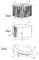
- Fig. 5 shows schematically a fractionation device in a view from above. It contains a housing 13 with a partially drawn cover 14.
- the sieve 1 is cylindrical Sieve basket, and the reamer 5 is designed as a cylindrical rotor.
- the rough one Surface 8 is indicated as a thick circular line.
- the suspension flows through the Inlet 15 between screen 1 and rotor.
- the sieve pass is through the Fine fraction outlet 16 and the sieve overflow through the coarse fraction outlet 17 dissipated.
- more than these two fractions can be formed e.g. several fine fractions with the help of differently designed Screen openings.
- Sieve and rotor are arranged concentrically to each other, but they are other embodiments are also conceivable.
- Fig. 6 shows a geometric representation of a circular cylindrical rotor trained reamer 5 with substantially axially parallel grooves 7.
- a shape inserted concentrically in a circular cylindrical sieve, has a very gentle Effect, i.e. generates no significant pressure / suction impulses.
- pressure / suction pulses are to be generated with Profile strips 18 are provided. These can also generate the Support parallel flow, e.g. with the help of a steep leading edge.
- the Profile strips 18 have only a small height F (Fig. 8). Your number can too be small, e.g. two to five spread over the circumference.
Landscapes
- Engineering & Computer Science (AREA)
- Mechanical Engineering (AREA)
- Paper (AREA)
- Preliminary Treatment Of Fibers (AREA)
Claims (11)
- Procédé pour le fractionnement d'une suspension contenant des fibres à papier, dans lequel la suspension (S) est divisée par un tamis (1, 1') en au moins deux fractions de fibres, un racleur (5) déplacé par rapport à ce tamis étant utilisé pour la libération du tamis,
caractérisé en ce que
à l'aide d'une surface (8) rugueuse du racleur (5), on génère un écoulement parallèle (4) sur le côté arrivée (2) du tamis (1, 1'),
en utilisant un racleur (5) qui est pourvu sur sa surface (8) d'une pluralité de cavités allongées, de préférence des rainures (7) ou d'une couche feutrée et facilement mouillable, et
la suspension (5) étant entraínée pratiquement sans glissement par le racleur (5) par le fait qu'elle est déplacée dans la zone de contact s'étendant jusqu'à un millimètre de la surface du racleur (5) à au moins 90% de la vitesse du racleur. - Procédé selon la revendication 1,
caractérisé en ce que
le racleur (5) est déplacé le long du côté arrivée (2) du tamis (1, 1') à une distance (A) de 20 mm maximum. - Procédé selon la revendication 1 ou 2,
caractérisé en ce que
le racleur (5) est déplacé à une vitesse d'au moins 10 m/s par rapport au tamis (1, 1'). - Procédé selon la revendication 3,
caractérisé en ce que
le racleur (5) est déplacé à une vitesse d'au moins 20 m/s par rapport au tamis (1, 1'). - Procédé selon l'une quelconque des revendications précédentes,
caractérisé en ce que
le racleur (5) ne génère pas d'impulsions de pression ou d'aspiration en direction du tamis (1, 1'). - Procédé selon l'une des revendications précédentes,
caractérisé en ce que
on fractionne avec un tamis (1, 1'), dont les orifices (6) sont allongés, présentant une extension longitudinale qui est située par rapport au sens de déplacement (3) du racleur (5) selon un angle d'attaque (β) compris entre 70° et 110°. - Procédé selon l'une quelconque des revendications précédentes,
caractérisé en ce que
on fractionne avec un tamis (1, 1'), sur lequel des tourbillons limités dans l'espace sont générés à l'aide de saillies ou de cavités conjointement avec l'écoulement parallèle (4). - Dispositif pour l'application du procédé selon l'une des revendications précédentes avec un boítier (13), dans lequel se trouve au moins un tamis (1, 1'), le long duquel un racleur (5) peut être déplacé du côté arrivée, afin d'empêcher l'obstruction des orifices (6) du tamis (1, 1'),
caractérisé en ce que
le racleur (5) présente une surface (8) fermée et rugueuse qui est formée par une couche de feutre. - Dispositif selon la revendication 8,
caractérisé en ce que
le tamis (1') est pourvu de saillies ou de cavités d'une hauteur ou profondeur maximum de 2 mm. - Dispositif selon la revendication 8 ou 9,
caractérisé en ce que
le tamis (1, 1') est un tamis cylindrique dans lequel un rotor cylindrique est disposé de façon rotative comme racleur (5). - Dispositif selon la revendication 10,
caractérisé en ce que
le panier de tamis et le rotor sont concentriques.
Applications Claiming Priority (2)
| Application Number | Priority Date | Filing Date | Title |
|---|---|---|---|
| DE19951711 | 1999-10-27 | ||
| DE19951711A DE19951711A1 (de) | 1999-10-27 | 1999-10-27 | Verfahren und Vorrichtung zum Fraktionieren einer papierfaserhaltigen Suspension |
Publications (2)
| Publication Number | Publication Date |
|---|---|
| EP1096063A1 EP1096063A1 (fr) | 2001-05-02 |
| EP1096063B1 true EP1096063B1 (fr) | 2004-08-11 |
Family
ID=7927027
Family Applications (1)
| Application Number | Title | Priority Date | Filing Date |
|---|---|---|---|
| EP00121414A Revoked EP1096063B1 (fr) | 1999-10-27 | 2000-09-29 | Procédé et dispositif de fractionnement d'une suspension de fibres à papier |
Country Status (5)
| Country | Link |
|---|---|
| US (1) | US6409023B1 (fr) |
| EP (1) | EP1096063B1 (fr) |
| AT (1) | ATE273415T1 (fr) |
| CA (1) | CA2324338A1 (fr) |
| DE (2) | DE19951711A1 (fr) |
Families Citing this family (3)
| Publication number | Priority date | Publication date | Assignee | Title |
|---|---|---|---|---|
| DE102007029806A1 (de) | 2007-06-27 | 2009-01-02 | Voith Patent Gmbh | Verfahren zur Aufbereitung von Altpapier |
| DE102007029805A1 (de) | 2007-06-27 | 2009-01-02 | Voith Patent Gmbh | Verfahren zur Erzeugung von mehrlagigem Karton oder Verpackungspapier aus Altpapier |
| CN114932652B (zh) * | 2022-04-11 | 2024-09-27 | 青岛天物金佰包装制品有限公司 | 一种eps泡沫充分熟化的熟化设备 |
Family Cites Families (7)
| Publication number | Priority date | Publication date | Assignee | Title |
|---|---|---|---|---|
| US3411721A (en) * | 1966-09-02 | 1968-11-19 | Ingersoll Rand Canada | Refining and screening apparatus |
| FI77279C (fi) * | 1987-04-30 | 1989-02-10 | Ahlstroem Oy | Foerfarande och anordning foer behandling av fibersuspension. |
| WO1988010335A1 (fr) * | 1987-06-26 | 1988-12-29 | A. Ahlstrom Corporation | Appareil pour tamiser la pate de cellulose et procede de tamisage d'une suspension de pate |
| FI92227C (fi) * | 1992-04-23 | 1994-10-10 | Ahlstroem Oy | Laite kuitususpension käsittelemiseksi |
| US5307939A (en) * | 1992-07-13 | 1994-05-03 | Ingersoll-Rand Company | Screening apparatus for papermaking pulp |
| US5385240A (en) * | 1993-04-30 | 1995-01-31 | The Black Clawson Company | Screening apparatus with adjustable hydrofoil portion |
| DE19836318A1 (de) * | 1998-08-11 | 1999-07-15 | Voith Sulzer Papiertech Patent | Rotor für Drucksortierer |
-
1999
- 1999-10-27 DE DE19951711A patent/DE19951711A1/de not_active Withdrawn
-
2000
- 2000-09-29 AT AT00121414T patent/ATE273415T1/de not_active IP Right Cessation
- 2000-09-29 DE DE50007359T patent/DE50007359D1/de not_active Revoked
- 2000-09-29 EP EP00121414A patent/EP1096063B1/fr not_active Revoked
- 2000-10-26 US US09/696,182 patent/US6409023B1/en not_active Expired - Fee Related
- 2000-10-26 CA CA002324338A patent/CA2324338A1/fr not_active Abandoned
Also Published As
| Publication number | Publication date |
|---|---|
| US6409023B1 (en) | 2002-06-25 |
| CA2324338A1 (fr) | 2001-04-27 |
| ATE273415T1 (de) | 2004-08-15 |
| DE19951711A1 (de) | 2001-05-03 |
| EP1096063A1 (fr) | 2001-05-02 |
| DE50007359D1 (de) | 2004-09-16 |
Similar Documents
| Publication | Publication Date | Title |
|---|---|---|
| DE69424661T2 (de) | Siebvorrichtung für papierbrei | |
| DE3686950T2 (de) | Verfahren und vorrichtung zur abtrennung von koerpern aus einer fluessigkeit. | |
| EP1059377B1 (fr) | Système d'aspiration destiné à une machine textile, en particulier à un dispositif d'aiguilletage hydraulique | |
| EP1036879B1 (fr) | Tamis sous pression pour suspensions fibreuses et un rotor de nettoyage pour un tel tamis | |
| EP1096063B1 (fr) | Procédé et dispositif de fractionnement d'une suspension de fibres à papier | |
| DE69511772T2 (de) | Zufuhrvorrichtung für einen Scheibenfilter | |
| EP1799903A1 (fr) | Procede pour fractionner une suspension aqueuse de fibres a papier et hydrocyclone pour la mise en oeuvre dudit procede | |
| DE69103602T3 (de) | Verfahren und vorrichtung zum trennen einer fasersuspension. | |
| DE69808945T2 (de) | Rakelanordnung für eine fasersiebvorrichtung | |
| DE2018510A1 (de) | Verfahren und Vorrichtung zum Fraktionieren von Holzzellstoff oder dergleichen | |
| EP2780505B1 (fr) | Tamis | |
| EP1884588A2 (fr) | Dispositif de nettoyage | |
| DE3025270A1 (de) | Vorrichtung zur reinigung und wiederaufbereitung von papierpulpe oder papierbrei | |
| DE4006633A1 (de) | Apparat zum fraktionieren von fasersuspension | |
| AT514845A1 (de) | Rotorelement und Rotor für eine Siebvorrichtung | |
| EP1039021B1 (fr) | Procédé de tammisage humide de suspensions fibreuses dans des tamis sous pression et tamis sous pression | |
| DE19805448C2 (de) | Verfahren und Vorrichtung zur Reinigung und Zuführung einer Papierstoffsuspension in den Stoffauflauf einer Papiermaschine | |
| DE10112478A1 (de) | Verfahren zum Sortieren einer Faserstoffsuspension | |
| DE2355768C2 (de) | Siebvorrichtung zum Sortieren von Suspensionen | |
| DE19736127A1 (de) | Verfahren und Siebvorrichtung zum Sortieren von nassen schmutzstoffhaltigen Faserstoffen | |
| DE1442501A1 (de) | Verfahren zum Ausscheiden von Fremdkoerpern aus einem fliessfaehigen Medium mittels eines Zyklons und Zyklon zur Ausuebung des Verfahrens | |
| DE3831845A1 (de) | Sortiereinrichtung fuer fasersuspensionen | |
| EP2893078B1 (fr) | Triage de fibres | |
| EP0807709A1 (fr) | Dispositif pour l'épuration d'une suspension fibreuse | |
| DE1236380B (de) | Pneumatische Vorrichtung zum Entstauben von Karden |
Legal Events
| Date | Code | Title | Description |
|---|---|---|---|
| PUAI | Public reference made under article 153(3) epc to a published international application that has entered the european phase |
Free format text: ORIGINAL CODE: 0009012 |
|
| AK | Designated contracting states |
Kind code of ref document: A1 Designated state(s): AT DE FI FR GB SE |
|
| AX | Request for extension of the european patent |
Free format text: AL;LT;LV;MK;RO;SI |
|
| 17P | Request for examination filed |
Effective date: 20011102 |
|
| AKX | Designation fees paid |
Free format text: AT DE FI FR GB SE |
|
| 17Q | First examination report despatched |
Effective date: 20031016 |
|
| GRAP | Despatch of communication of intention to grant a patent |
Free format text: ORIGINAL CODE: EPIDOSNIGR1 |
|
| GRAS | Grant fee paid |
Free format text: ORIGINAL CODE: EPIDOSNIGR3 |
|
| GRAA | (expected) grant |
Free format text: ORIGINAL CODE: 0009210 |
|
| AK | Designated contracting states |
Kind code of ref document: B1 Designated state(s): AT DE FI FR GB SE |
|
| REG | Reference to a national code |
Ref country code: GB Ref legal event code: FG4D Free format text: NOT ENGLISH |
|
| GBT | Gb: translation of ep patent filed (gb section 77(6)(a)/1977) |
Effective date: 20040811 |
|
| REF | Corresponds to: |
Ref document number: 50007359 Country of ref document: DE Date of ref document: 20040916 Kind code of ref document: P |
|
| REG | Reference to a national code |
Ref country code: SE Ref legal event code: TRGR |
|
| ET | Fr: translation filed | ||
| PLAQ | Examination of admissibility of opposition: information related to despatch of communication + time limit deleted |
Free format text: ORIGINAL CODE: EPIDOSDOPE2 |
|
| PLAR | Examination of admissibility of opposition: information related to receipt of reply deleted |
Free format text: ORIGINAL CODE: EPIDOSDOPE4 |
|
| PLBQ | Unpublished change to opponent data |
Free format text: ORIGINAL CODE: EPIDOS OPPO |
|
| PLBI | Opposition filed |
Free format text: ORIGINAL CODE: 0009260 |
|
| PLAQ | Examination of admissibility of opposition: information related to despatch of communication + time limit deleted |
Free format text: ORIGINAL CODE: EPIDOSDOPE2 |
|
| PLAR | Examination of admissibility of opposition: information related to receipt of reply deleted |
Free format text: ORIGINAL CODE: EPIDOSDOPE4 |
|
| PLAX | Notice of opposition and request to file observation + time limit sent |
Free format text: ORIGINAL CODE: EPIDOSNOBS2 |
|
| PLBQ | Unpublished change to opponent data |
Free format text: ORIGINAL CODE: EPIDOS OPPO |
|
| PLAB | Opposition data, opponent's data or that of the opponent's representative modified |
Free format text: ORIGINAL CODE: 0009299OPPO |
|
| 26 | Opposition filed |
Opponent name: ADVANCED FIBER TECHNOLOGIES (AFT) OY Effective date: 20050509 |
|
| R26 | Opposition filed (corrected) |
Opponent name: ADVANCED FIBER TECHNOLOGIES (AFT) OY Effective date: 20050509 |
|
| PGFP | Annual fee paid to national office [announced via postgrant information from national office to epo] |
Ref country code: FR Payment date: 20050823 Year of fee payment: 6 |
|
| PGFP | Annual fee paid to national office [announced via postgrant information from national office to epo] |
Ref country code: DE Payment date: 20050912 Year of fee payment: 6 |
|
| PGFP | Annual fee paid to national office [announced via postgrant information from national office to epo] |
Ref country code: SE Payment date: 20050914 Year of fee payment: 6 |
|
| PGFP | Annual fee paid to national office [announced via postgrant information from national office to epo] |
Ref country code: FI Payment date: 20050915 Year of fee payment: 6 |
|
| PGFP | Annual fee paid to national office [announced via postgrant information from national office to epo] |
Ref country code: AT Payment date: 20050919 Year of fee payment: 6 Ref country code: GB Payment date: 20050919 Year of fee payment: 6 |
|
| RDAF | Communication despatched that patent is revoked |
Free format text: ORIGINAL CODE: EPIDOSNREV1 |
|
| PLBB | Reply of patent proprietor to notice(s) of opposition received |
Free format text: ORIGINAL CODE: EPIDOSNOBS3 |
|
| RDAG | Patent revoked |
Free format text: ORIGINAL CODE: 0009271 |
|
| STAA | Information on the status of an ep patent application or granted ep patent |
Free format text: STATUS: PATENT REVOKED |
|
| 27W | Patent revoked |
Effective date: 20051106 |
|
| GBPR | Gb: patent revoked under art. 102 of the ep convention designating the uk as contracting state |
Free format text: 20051106 |
|
| REG | Reference to a national code |
Ref country code: SE Ref legal event code: ECNC |